** NEW IMPROVED WEB STORE! | All users must register for a new account. | Register now > **
BUY ONLINE TO SAVE TIME AND INCREASE ORDER ACCURACY!


The previous article in this series, the Fundamentals of Loop-Powered Devices, discussed loop-powered or two-wire devices. These instruments utilize the power supplied to the current loop to power themselves. A two-wire connection may not always be the most optimal power solution because of its inability to power devices that require a large voltage drop. Three and four-wire devices incorporate an external power supply in order to effectively eliminate the voltage drop placed on the process signal current loop. It is important to understand the differences between these three setups as they are fundamentally different and each has its own advantages and limitations.
Defining 2, 3, and 4 Wire Connections
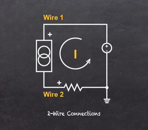
2-Wire Connections
All devices in a 4-20 mA current loop need to be supplied power from somewhere in order to function. Two-wire devices receive their power from the process signal loop itself. The power for the loop usually comes from the transmitter power supply or some other kind of external power supply, and all of the power for the system travels through the wires that also carry the signal. Since this setup only requires two wires, loop-powered instruments are also referred to as two-wire devices. Three and four-wire devices, by contrast, receive the power they require to function from a power supply that is separate (but not necessarily isolated) from the current loop. These devices cannot be loop-powered.
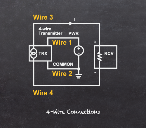
4-Wire Connections
A four-wire connection uses the current loop as a means to transmit the 4-20 mA process signal only. This type of connection will not draw the power it needs from the current loop. It will create a voltage drop on the loop, but this is minimal when compared to that of a loop-powered device. The power four-wire devices need is instead provided by an external power supply. This can be either an alternating or direct current power supply because the device is powered independently from the direct current loop. 24 VAC or VDC supplies are common, as are 120 or 240 VAC. It all depends on the specifications of the device.
Isolated four-wire connected devices "float" within the current loop. This means that the common, or the return process signal wire from the device does not connect to the power supply ground. As may be apparent from the name "four-wire," two wires connect the power supply to the device and two wires connect the process signal to the device. Isolation, therefore, is built into the system. There is no electrical connection between the power supply and the process signal.
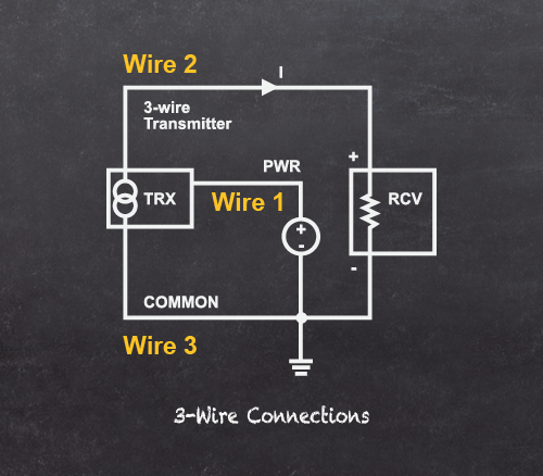
3-Wire Connections
A three-wire connection is essentially the same as a four-wire connection except that the isolation just discussed is not present; a three-wire device does not float in comparison to the current loop. In a three-wire connection, the process signal return from the device and the common of the power supply are a shared connection.
Recalling the advantages of two-wire connections from the previous article, you will remember that they are simple to setup, lower cost, commonly feature hazardous area approvals, and do not require local power.
On the other hand, they have very limited features due to the limited amount of power they can draw from the current loop. Three and four-wire devices have their own set of pros and cons which must always be taken into account when attempting to determine the best solution for a process control environment.
Understanding The Pros and Cons
2-Wire Connections
Recalling the advantages of two-wire connections from the previous article, you will remember that they are simple to setup, lower cost, commonly feature hazardous area approvals, and do not require local power.
On the other hand, they have very limited features due to the limited amount of power they can draw from the current loop. Three and four-wire devices have their own set of pros and cons which must always be taken into account when attempting to determine the best solution for a process control environment.
Pros
- Simple and easy display for 4-20 mA transmitter
- Low cost solution for display
- Agency approvals
- Local power not required
Cons
- Limited output options
- Does not support relays
- Does not support LED displays
4-Wire Connections
Because four-wire devices are externally powered, they can accommodate a lot more energy intensive features such as mechanical relays, bright LED displays, advanced serial communications such as Modbus®, and powered outputs, among other things. Four-wire connections can be easier to understand because there is no need to worry about voltage drop across the current loop. A four-wire device can be powered by simply plugging it into a wall outlet or some sort of DC power supply such as a battery.
As mentioned, four-wire devices often have excellent built in signal isolation. In a device with power-to-signal isolation, the current signal and the power supply utilize completely separate wires. This can make setup and maintenance a whole lot easier when dealing with complex 4-20 mA signal networks (featuring multiple 4-20 mA process variables over multiple loops) or if there is a lot of electronic noise from the power supply.
Four-wire connections, as opposed to two-wire connections, require a separate power supply for the device, which can be disadvantageous depending on the availability of power. Generally they are more expensive as they require an internal power supply circuit to handle the external power they are receiving and generally feature more expensive components.
The amount of wire needed to connect four-wire devices can become a problem for installers, especially in hazardous areas where all of that wire would need to run through conduit. This can also make maintenance and troubleshooting more difficult down the road, requiring evaluation and repair of nearly double the circuitry compared to a similar two-wire system.
Four-wire connections also have fewer options when it comes to hazardous areas. The high power requirements alone make Intrinsic Safety (I.S.) and Non-incendive (N.I.) approvals exceedingly rare. In order for a four-wire device to be suitable for use in a hazardous area, it often needs to be enclosed in an explosion-proof enclosure which, though effective, might not always be the best possible option.
Pros
- More capabilities than 2 wire (relays, LEDs, serial communications)
- Easier to understand the wiring
- No need to worry about voltage drop
- Excellent isolation (power from input/outputs)
Cons
- Requires a separate local power supply
- Generally more expensive
- More wiring requirements
- Limited hazardous area options
3-Wire Connections
Three-wire devices are commonly found to be lower cost than four-wire primarily because they do not feature isolation. They can also be slightly easier to install because they require less wire and, in the case where wire needs to be run through conduit, this wire can often be run along the same channels because they are already electrically connected. Moreover, many of the same benefits of four-wire devices mentioned above also apply to three-wire, such as the availability of mechanical relays, advanced serial communication, powered outputs, etc.
In contrast to four-wire, three-wire devices do not feature isolation because of the fact that the power supply common and the process signal return share the same wire. When dealing with complex 4-20 mA signal networks, an installer must be very careful while wiring the devices to avoid crossing current paths. Any grounds, commons or returns that cross paths with the process signal loop will cause current to travel into different circuits and the process signal will no longer provide predictable, usable current values.
Three wire devices cannot be powered by an alternating current (AC) power supply. Four-wire devices can be powered via AC current, such as that available from a wall outlet, because the connection powering the device is completely separate from the connection to the process signal. Three-wire devices do not feature this isolation, so all of the power in the system must be direct current (DC), just like the process signal loop.
Pros
- Lower cost than 4 wire
- Easier to wire (fewer connections)
Cons
- No isolation, very susceptible to ground loops
- May be confusing to wire
Choosing The Right Wiring For Your Application
At the core of this topic are a few essential factors which need to be taken into consideration when deciding on the right choice for a process control environment. Remember that three and four-wire devices will always require a power supply that is separate from the process signal loop, though this does not inherently imply isolation. Two-wire devices are powered by the current loop itself and do not require an external power supply.
Although there were many cons mentioned in regard to three-wire connections, remember that they do work and they are a valid option when power supply isolation is not a concern. They are often cheaper than four-wire devices, which is a definite plus; however, the installer needs to understand what they are doing and know the implications of crossing current loops.
Four and two-wire devices can be easier to connect than three-wire, though both for different reasons. Two-wire devices are easier because there are less connections to make, but voltage drop must be taken into account. Four-wire devices are easier to connect because of the built in isolation, but external power requirements must be taken into account.
As a general rule of thumb when it comes to the cost of process control devices, think of two-wire devices being the least expensive, three-wire being in the middle, and four-wire devices as the most expensive. Some devices and device features are just not available as two-wire, however, because of inherent power consumption requirements.
Things to Remember
- 4-wire or 3-wire require a separate power supply
- 3-wire works – be aware of isolation requirements first
- 2-wire – be aware of voltage drops
- Costs increase as more wires are used
- Some devices are not available as 2-wire
Back to Basics: Series Summary
As discussed in the first part of this series, The Fundamentals of 4-20 mA Current Loops, the 4-20 mA current loop is the dominant process control signal standard in many industries which require process control. The fact that the current will not change from the time it leaves the transmitter to when it reaches the receiver makes it an ideal means for transferring process information. It is also much simpler and cost effective than other process control protocols. However, voltage drops and number of process variables that need to be monitored can have an impact on the cost and complexity of implementing this standard.
Devices which transmit and/or receive information over a current loop are connected with either two, three or four wires. Part two, The Fundamentals of Loop-Powered Devices, explored how two-wire, or loop-powered, devices receive their power from the 4-20 mA process signal loop connected to the device. This is possible because current is the same throughout the loop, so voltage drops caused by loop-powered devices do not affect the current signal. Loop-powered devices are simple, easy to wire and use very little power. However, it is important to be aware of the limitations of loop-powered devices such as the unavailability of relays, LED displays, or advanced serial communications.
Three and four-wire devices, unlike two-wire, utilize an external power supply which allows them to feature much more advanced components such as brighter LED displays and advanced output options. Four-wire devices also frequently feature built in power supply isolation. Three and four-wire devices might not always be the appropriate option, however, if running additional power is infeasible or they need to operate in a hazardous area with Intrinsic Safety or Non-incendive approvals.
A device installer must be able to pay attention to the specifications relevant to their particular process control environment in order to avoid problems with their specific control system. Maintenance personnel should know how the environment is setup, and what that means in terms of electrical connectivity, in order to properly maintain and troubleshoot existing process control networks. Knowing the fundamentals of the 4-20 mA current loop standard and means by which devices connect to current loop networks can go a long way towards being able to make more informed decisions about process control in your facility.
By Simon Paonessa - Technical Writer
Precision Digital Corporation
Watch: Loop vs. Line Power
Watch this recorded webinar designed as an introductory class for those who have to deal with process signals. Gain a strong understanding of the key differences between the 2 wire, 3 wire and 4 wire connections. You'll be well equipped to determine the best choice for your applications and make the best decisions for your instruments and meters.