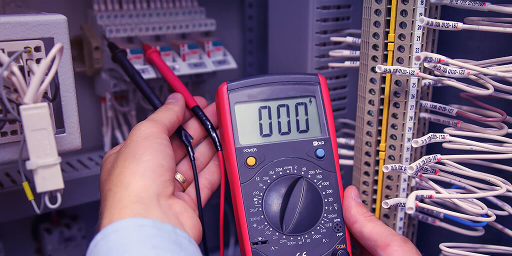
For decades, process instrumentation has largely relied on 4-20 mA signals to transmit process data easily and reliably. Moreover, it is the signal of choice in the process control industry for many reasons. One in particular is the fact that current does not degrade and it remains constant at any point in the loop, as discussed in our review of the Fundamentals of 4-20 mA Current Loops. Therefore, it is a very efficient means to transmit process information. In most cases, this range represents a two-point linear scale where a 4 mA signal represents 0% of a sensor's measurement, while 20 mA indicates 100% of the measurement1. But, why do we use 4-20 mA instead of 0-20 mA? That is a very common question among individuals in the industry. And the answer is simple; a 0 mA signal is not practical. This article will discuss three reasons why a 0 mA signal is not as useful and why 4-20 mA is the industry standard.
Before we delve into the reasons why a 0 mA signal is not practical, let's get to know a little bit of the history behind the 4-20 mA signal. Prior to the invention of electronic circuitry, process control systems used pneumatic control signals2. In these systems, controllers were powered by distinct pressures of compressed air. Eventually, air compression of 3-15 psi became the industry standard for a few reasons. First, it was very expensive to engineer a system that would detect pressure signals under 3 psi. Second, signals below 3 psi were unrecognizable. Lastly, using 3 psi to indicate a value of 0% measurement made it easier to identify when system faults occurred, in other words, when the signal dropped to zero. As electronic systems made their debut in the 1950s, current became the preferred, more precise, and more efficient process control signal. Later, the industry established the 4-20 mA signal as the standard for similar reasons as those that made 3-15 psi range an effective signal. Now let’s take a look at why a 0 mA signal is not efficient.
1. Difficult and Expensive
A 0 mA signal is essentially an open circuit in which no flow of current exists at all. Thus, engineering any device with circuitry capable of handling a signal level that reaches 0 mA and remains accurate is more difficult and expensive than limiting the design to 4-20 mA. This was especially true during the 1950s when electrical signals like 4-20 mA had just emerged and surpassed pneumatic signals like the old 3-15 psi standard. Further, in a circuit where 0-20 mA is used, it would be very hard to detect and distinguish low ranges. A 4-20 mA circuit is much easier to work with because there is in fact a consistent flow of current that can be detected and used to reliably transmit process information3. As a result, the industry adopted the 4-20 mA range for its cost efficiency as well as other similar benefits that made the former 3-15 psi signal popular.
2. Inability to Detect a System Failure
Another reason why a 0 mA signal is not efficient is the inability to clearly differentiate between a measurement of zero and a system failure in which the signal would drop to zero. The term live zero is used to describe a loop signal where the zero value is a number higher than zero (i.e. 4 mA)4. The term dead zero denotes a loop signal where the zero value is indeed zero (i.e. 0 mA). The advantage of using a live zero versus a dead zero is that it allows receiving instruments to quickly detect when a system failure has occurred due to a break in the line, devices wired incorrectly, etc. Again, that is because a live zero interprets 4 mA as 0% of the sensor’s measurement, and when current falls to any number below 4 mA then that is an indicator of a fault in the system5.
3. Does Not Allow Devices to Operate
Lastly, a 0 mA signal does not provide a loop-powered, or two-wire, device with a minimum amount of current to function. Loop-powered transmitters, displays, and other equipment require some power for operation, which is drawn from the current flowing through the loop6. In a situation where a 0 mA signal exists, that means there is no flow of current at all in the loop, thus it is unable to meet the minimum current requirements to power up the connected devices. Even without the 0 mA problem, designing loop-powered instruments is not easy because of power requirements and the need to maintain a low loop voltage drop; which would be even more difficult to support at currents well below 4 mA. As a result, using a 4-20 mA signal is preferred because it supports two-wire transmission that supplies the power needed for loop-powered devices like transmitters and displays to operate.
Related: Back to Basics: Loop vs Line Power
Why 4-20 mA is the Industry Standard
Now that we have reviewed the reasons why a 0 mA signal is not practical, it's easy to see why the process control industry has preferred the 4-20 mA signal range. In addition, it provides other benefits such as easier wiring, easier configuration, it’s more cost-effective, it’s better for traveling long distances7, and it is less sensitive to background electrical noise than many other signals available. Another benefit of a 4-20 mA signal is safety. The low current is not an electrical shock hazard and it is also an easy signal to work with when designing equipment to be intrinsically safe for hazardous areas8. If you would like to learn more about this and other analog signals, then check out the ANSI/ISA-50.00.01-1975 (R2012) Compatibility of Analog Signals for Electronic Industrial Process Instruments .
By Del Mauricio – Marketing Communications Specialist
References
- Kuphaldt, Tony R. "Electrical Instrumentation Signals." Current Signal Systems. All About Circuits. Accessed 13 Nov 2018.
allaboutcircuits.com/textbook/direct-current/chpt-9/current-signal-systems/ - "The Science of 4 to 20 mA Current Loops – Application Note." BAPI, Accessed 12 Nov 2018.
bapihvac.com/application-note/the-science-of-4-to-20-ma-current-loops-application-note/ - Heath, Janet. "Why Do Industrial Sensors Measure in 4-20mA to Programmable Logic Controllers?" Analog IC Tips. 14 Nov 2016.
analogictips.com/faq-industrial-sensors-measure-4-20ma-programmable-logic-controllers/ - Kuphaldt, Tony R. "Electrical Instrumentation Signals." Analog and Digital Signals. All About Circuits. Accessed 13 Nov 2018.
allaboutcircuits.com/textbook/direct-current/chpt-9/analog-and-digital-signals/ - NAMUR standard NE 043 "Standardisation of the Signal Level for the Failure Information of Digital Transmitters"
- Paonessa, Simon. "Back to Basics: Loop vs Line Power." Precision Digital Corp. Accessed 9 Nov 2018.
predig.com/indicatorpage/back-basics-loop-vs-line-power - Rosenberger, Scott. "Analog Signals: 0 to 10V Vs. 4-20 mA." Automation Insights. Accessed 13 Nov 2018.
automation-insights.blog/2010/06/22/analog-signals-0-to-10v-vs-4-20-ma/ - Heath, Janet. "Why Do Industrial Sensors Measure in 4-20mA to Programmable Logic Controllers?" Analog IC Tips. 14 Nov 2016.
analogictips.com/faq-industrial-sensors-measure-4-20ma-programmable-logic-controllers/
You may be interested in
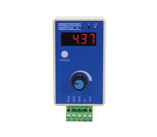
PD9502 Low-Cost Signal Generator
A low-cost, compact, simple to use 4-20 mA or 0-10 VDC signal generator.
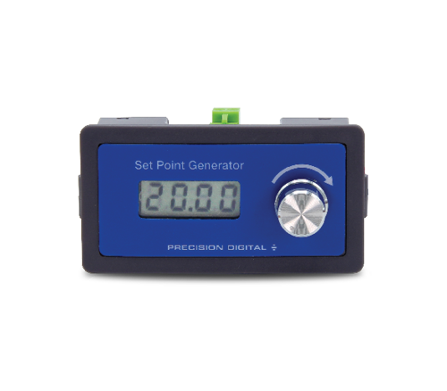
PD420 Panel Mount 4-20 mA Set-Point Generator
Provides a convenient way to generate a 4-20 mA signal that can be used to control another device.