** NEW IMPROVED WEB STORE! | All users must register for a new account. | Register now > **
BUY ONLINE TO SAVE TIME AND INCREASE ORDER ACCURACY!


In the world of process control, there are a myriad of different types of process inputs. Thermocouples and RTDs provide direct temperature reading while digital signals such as Modbus provide exacting control over process variables and display. Analog signals, where information about the process is transmitted via varying amounts of voltage or current, are the predominant type of input in industries requiring process control today. Of all possible analog signals that can be used to transmit process information, the 4-20 mA loop is, by far, the dominant standard in the industry.
As major as the 4-20 mA loop standard has become in the process control industry, many do not understand the fundamentals of its setup and use. Not knowing the basics could potentially cost you money when it comes time to make decisions about process display and control. Having a grasp on the history, workings, pros and cons of the 4-20 mA loop will help you to understand why it is the dominant standard for the industry and allow you to make informed decisions about your process control.
A Little Bit of History
Before the advent of electronic circuitry, process control was a wholly mechanical endeavor. Facilities used pneumatic control signals where controllers were powered by varying pressures of compressed air. Ultimately, air compression of 3-15 psi became the standard for a few reasons:
- It is very expensive to engineer systems detecting pressure signals under 3 psi
- Signals below 3 psi would be unrecognizable
- Easier to differentiate a live zero (3 psi) signal from a failure in the system (0 psi)
In the 1950s, as electronic systems became less expensive, current input became the preferred and more efficient process control signal. The 4-20 mA range later became the standard for similar reasons as 3-15 psi did.
How Does a 4-20 mA Current Loop Work?
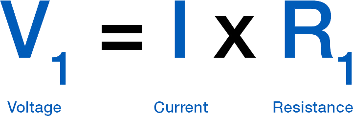
In order to understand what a 4-20 mA direct current (DC) loop is and how it works, we will need to know a little bit of math. Don't worry; we won't be delving into any advanced electrical engineering formulas. In fact, the formula we need is relatively simple: V = I x R. This is Ohm's Law. What this is saying is that the voltage (V) is equal to the current (I) multiplied by the resistance (R) ("I" stands for Intensité de Courant, French for Current Intensity). This is the fundamental equation in electrical engineering.
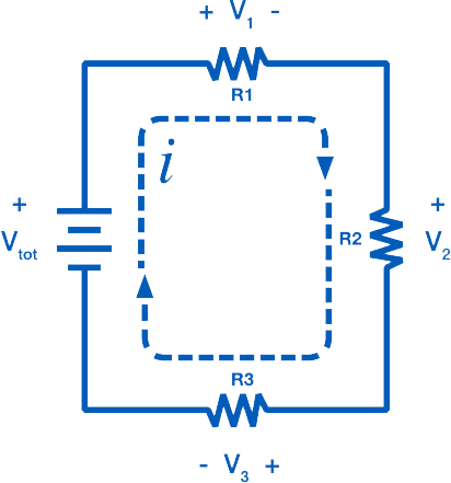
Consider the simple DC circuit in Figure 1, consisting of a power supply and three loads. A current loop requires voltage to drive the current. This is provided by the power supply, with the voltage of the supply labeled as Vtot. Current then flows through the loop, passing through each load. The voltage drop at each load can be calculated from Ohm's Law.
The voltage drop V1 across R1 is:
Every element in the loop either provides voltage or has a voltage drop. However, the current, "I" is the same everywhere in the loop. This is the critical principle of the 4-20 mA loop. Current is the same in all places throughout the loop. It may be difficult to understand why the current remains constant, so consider your home's water system as a comparison. There is a certain amount of pressure in the water pipes pushing the water towards your house.
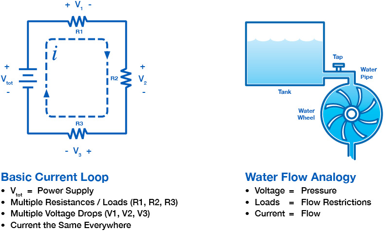
Voltage, in a similar fashion, acts as a pressure, pushing current through the circuit. When a tap inside your home is turned on, there is a subsequent flow of water. The flow of water is analogous to the flow of electrons, or current. The ability of the pressure to push the water through the pipes is limited by bends and restrictions in the pipe. These restrictions limit the amount of flow in the pipe, similar to how a resistor limits the current. The flow through the pipe, and likewise the current through the wire, remains constant throughout the system, even though pressure, and likewise voltage, will drop at various points. This is why using current as a means of conveying process information is so reliable.
Featured:PD9502 Low-Cost Signal Generator
Components of a 4-20 mA Current Loop
Now that you have an understanding of how and why current is used, you can begin to understand what exactly the loop is for.
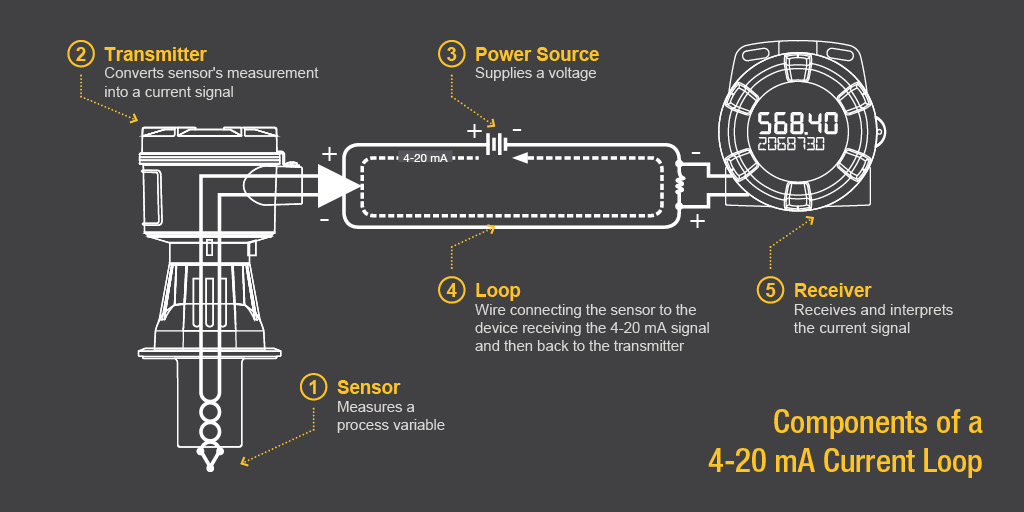
1. Sensor
First, there needs to be some sort of sensor which measures a process variable. A sensor typically measures temperature, humidity, flow, level or pressure. The technology that goes into the sensor will vary drastically depending on what exactly it is intended to measure, but this is not relevant for this discussion.
2. Transmitter
Second, whatever the sensor is monitoring, there needs to be a way to convert its measurement into a current signal, between four and twenty milliamps. This is where a transmitter will come into play. If, for instance, a sensor was measuring the height of a fifty foot tank, the transmitter would need to translate zero feet as the tank being empty and then transmit a four milliamp signal. Conversely, it would translate fifty feet as the tank being full and would then transmit a twenty milliamp signal. If the tank were half full the transmitter would signal at the halfway point, or twelve milliamps.
3. Power Source
In order for a signal to be produced, there needs to be a source of power, just as in the water system analogy there needed to be a source of water pressure. Remember that the power supply must output a DC current (meaning that the current is only flowing in one direction).
There are many common voltages that are used with 4-20 mA current loops (9, 12, 24, etc.) depending on the particular setup. When deciding on what voltage of power supply to use for your particular setup, be sure to consider that the power supply voltage must be at least 10% greater than the total voltage drop of the attached components (the transmitter, receiver and even wire). The use of improper power supplies can lead to equipment failure.
4. Loop
In addition to an adequate VDC supply, there also needs to be a loop, which refers to the actual wire connecting the sensor to the device receiving the 4-20 mA signal and then back to the transmitter. The current signal on the loop is regulated by the transmitter according to the sensor's measurement. This component is typically overlooked in a current loop setup because wire is so intrinsic to any modern electronic system, but should be considered in our exploration of the fundamentals. While the wire itself is a source of resistance that causes a voltage drop on the system, it is normally not a concern, as the voltage drop of a section of wire is minuscule. However, over long distances (greater than 1,000 feet) it can add up to a significant amount, depending on the thickness (gauge) of the wire.
5. Receiver
Finally, at someplace in the loop there will be a device which can receive and interpret the current signal. This current signal must be translated into units that can be easily understood by operators, such as the feet of liquid in a tank or the degrees Celsius of a liquid. This device also needs to either display the information received (for monitoring purposes) or automatically do something with that information. Digital displays, controllers, actuators, and valves are common devices to incorporate into the loop.
These components are all it takes to complete a 4-20 mA current loop. The sensor measures a process variable, the transmitter translates that measurement into a current signal, the signal travels through a wire loop to a receiver, and the receiver displays or performs an action with that signal.
Pros & Cons of 4-20 mA Loops
Part of the challenge of working in an industry which requires process control is determining if the pros outweigh the cons. Making the right decision can save both time and money.
Pros
- The 4-20 mA current loop is the dominant standard in many industries.
- It is the simplest option to connect and configure.
- It uses less wiring and connections than other signals, greatly reducing initial setup costs.
- Better for traveling long distances, as current does not degrade over long connections like voltage.
- It is less sensitive to background electrical noise.
- Since 4 mA is equal to 0% output, it is incredibly simple to detect a fault in the system.
Cons
- Current loops can only transmit one particular process signal.
- Multiple loops must be created in situations where there are numerous process variables that require transmission. Running so much wire could lead to problems with ground loops if independent loops are not properly isolated.
- These isolation requirements become exponentially more complicated as the number of loops increases.
Featured:PD420 Panel Mount 4-20 mA Set-Point Generator
4-20 mA Current Loops Overview
The 4-20 mA current loop is the prevailing process control signal in many industries. It is an ideal method of transferring process information because current does not change as it travels from transmitter to receiver. It is also much simpler and cost effective. However, voltage drops and the number of process variables that need to be monitored can impact its cost and complexity. By knowing these fundamentals you will be able to make more informed decisions about process control in your facility which could affect your bottom line.
By Simon Paonessa - Technical Writer
Bruce McDuffee - Technical Writer
Precision Digital Corporation
Watch: The Fundamentals of 4-20 mA Current Loops
Watch this recorded webinar designed as an introductory class for those who have to deal with process signals. Gain a strong understanding of the fundamentals of 4-20 mA current loops, and be better equipped to decide when, where, or if a 4-20 mA current loop solution is right for your application.