
Ground Loops & Non-Isolated Commons
Any installer of industrial process control equipment will tell you that ground loops are one of the most frustrating signal connection errors to diagnose and repair. The steps required in order to troubleshoot them are often equated to something as mysterious as magical incantations. Issues caused by shared, non-isolated commons are viewed with a similar outlook. Difficulties with shared signal returns are often even confused with ground loops. Ground loops and shared commons can both cause unpredictable signals and render your current loop unusable.
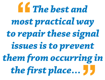
The best and most practical way to repair these signal issues is to prevent them from occurring in the first place by planning proper device wiring and following specific best practices. However, if you suspect that you are having signal issues related to ground loops or shared commons in an existing network, no need to pull out the spell Ground Loops & Non-Isolated Commons book and magic wand, there are some predictable symptoms which you can look for in order to diagnose the problem.
First of all, you need to know the definition of ground loops and shared commons. A ground loop is the flow of current from one signal ground to another because of a voltage differential between the two grounds. This can happen if two devices in the network are grounded at separate locations and one of the locations causes the signal ground there to experience a higher voltage potential. As any electrical engineer will tell you, any voltage differential will result in a current flow. It is this current flow that causes the symptoms of a ground loop.
A shared, non-isolated common can become problematic when it is improperly wired. Multi-input and multioutput devices, especially those with more than one loop going through them, are notorious for difficulties related to shared commons. These are commonly referred to as "ground loops" because of the similarity of their symptoms, but are not true ground loops because they are not caused by grounding issues. These kinds of problems arise when nodes are created, intentionally or not, prior to reaching all of the applicable devices on the circuit requiring a clean, predictable signal. This will result in mixed current flow and signal averaging, which will produce an unusable process signal.
GROUND LOOPS
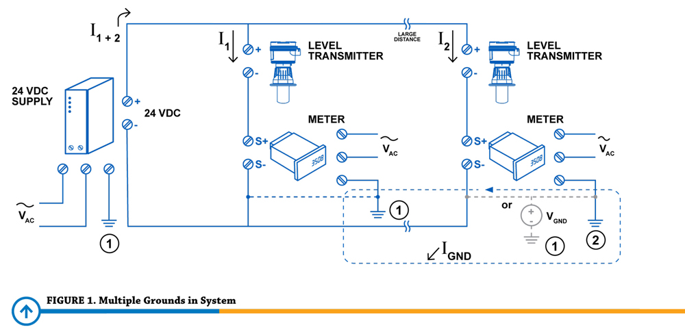
Figure 1 above shows a 24 VDC power supply providing voltage to the current loop. This loop is connected in parallel to two level transmitter/local display pairs, presumably on different tanks at completely separate locations in an industrial facility. The two transmitters are using the voltage provided to them to generate a 4-20 mA process signal which is then run along the wire connecting them to the local display showing the process variable. The circuit is completed by running a return back to the power supply.
This all sounds like a typical,functional current loop until you notice that both of the local displays' power inputs are grounded at their individual locations. Ground 2, because the environment in which it is located experiences more noise and has inferior connections for its grounding rails than the other location, has a higher voltage potential than ground 1. This results in the current flow labeled IGND above. This current flow runs along the same wires that are supposed to only carry the 4-20 mA process signal to the displays, resulting in the two currents mixing and the process signal becoming unpredictable and therefore unusable.
In the example illustrated in Figure 1, it was a device on the 4-20 mA loop which was injecting ground current onto the loop. It is possible, however, that a device not located on the loop can be the culprit. Consider if some device on the loop is connected via non-isolated RS-485 or input/output power to a device that has a higher voltage potential ground. Multi-point grounding of devices in a current loop is generally best avoided. Ground potentials are often unequal because of different electrical noise, ground path resistances, and poor initial power rail installation.
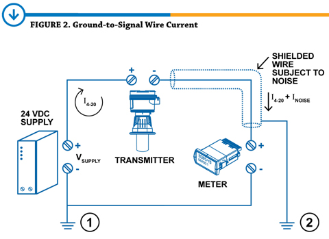
A ground loop can occur in a single-point grounded system as well. Consider a system in which insulated twisted pair wires are not used, such as the one illustrated in Figure 2. Any electrical noise picked up by the ground wire, such as stray magnetic fields or 50/60 Hz AC power supply noise, may be injected onto the current loop and result in an unpredictable signal. This type of ground loop is most often caused by improper pathing and the lack of shielded twisted pair wire.
NON-ISOLATED COMMONS
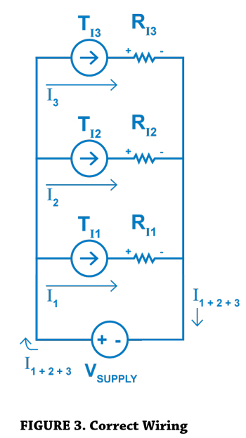
Figure 3 shows a properly wired current loop and Figure 4 an improperly wired current loop. In Figure 3, the voltage potential supplied by the power supply causes a current flow to each of the three parallel transmitters. This current is used to produce a 4-20 mA current signal which is sent along to local displays which show the process variable.
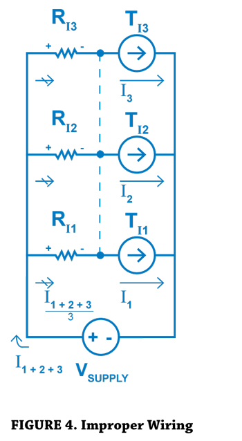
In Figure 4, the devices have been wired haphazardly because, in a series electrical circuit, the order of devices does not normally matter. However, a node has been created on a shared common of a multi-input device, connecting the current signals. This results in the process signal currents mixing and being averaged out, causing all of the displays to show the same value. These images make this type of issue seem trivial
to repair: simply remove the additional junction from the circuit. However, when complex networks of equipment experience this very same issue, the solution is not always quite as intuitive.
Problems like this are most commonly caused by the inclusion of non-isolated multi-input devices such as low cost PLCs. Because the device has multiple physical current inputs, an installer might make the assumption that each input is isolated. However, if these inputs are internally connected, the current signals will merge causing the current to average out before continuing through the circuit. This problem can also be caused by improper wiring of three wire devices or complex multi-loop networks.
SYMPTOMS
Because of the nature of signal connection problems and the unique variables present in industrial facilities, the symptoms caused by these problems are going to also be unique. Nonetheless, there are some general cues that can be looked for if you suspect that you are experiencing one of these issues with your existing network.
Unpredictable signal fluctuations are a sure sign that something is interfering with your current loop. This is likely the result of electrical noise or a ground loop.
The signal may also experience an addition or subtraction by some value from one point in the loop to another. This addition or subtraction could even put the signal out of range of the devices designated to measure the signal.
Problems with shared, non-isolated commons will commonly average the process signal causing the same value variable to be registered on devices which should be receiving different process variables.
The most drastic (and thankfully rare) symptom of these problems is physical damage to the devices on the network. If the voltage differential between two grounds, for instance, happens to be substantial, it could overwhelm the sensitive signal electronics of the devices such as the signal inputs and outputs. Damage to higher-level electronics such as power supplies and relays is exceedingly rare, due to their ability to withstand very high voltage potentials.
INSTALLATION BEST PRACTICES
As mentioned previously, the best way to repair ground loops is to avoid them in the first place. Multipoint grounding problems can be alleviated by only using a single-point ground. Any two grounding locations will have different voltage potentials, though the severity of this differential is a matter of the environment in which they are located. Whenever possible, use floating (non-grounded) devices. If there is a situation in which multiple devices in a network must be grounded (for safety reasons, etc.) make sure to carry the ground throughout the entire system, on shielded cable through conduit when possible.
All wire in the system should be shielded twisted pair in which both wires are used. All signals should be isolated whenever possible and within budget using devices with isolated inputs and outputs. Lastly, always be aware of non-isolated multi-loop devices and take extra care while planning your wiring. By following these few installation best practices whenever you install process control equipment, you can save yourself a lot of headache trying to diagnose and repair these issues in the future.
SUMMARY
Ground loops and non-isolated commons can be a nuisance for both industrial process control equipment installers and maintenance personnel, but they can be easily avoided by good planning and installing practices. Ground loops cause problems for systems when multiple devices are grounded at different locations that have different voltage potentials or when improperly wired, grounded devices experience noise injection from their ground connection. Nonisolated shared commons can become an issue when current paths cross and become unpredictable. These two signal connection problems can lead to unpredictable, incorrect, out of range, or averaged process signals and, in rare cases, damage to devices. This can all be avoided, not with the use of magical incantations, but by following standard installation best practices that can reduce or potentially eliminate the current quandary.
If you have an idea for a future topic to be featured in The Current Quandary, please contact Precision Digital at [email protected]
by Simon Paonessa - Technical Writer, Precision Digital Corporation