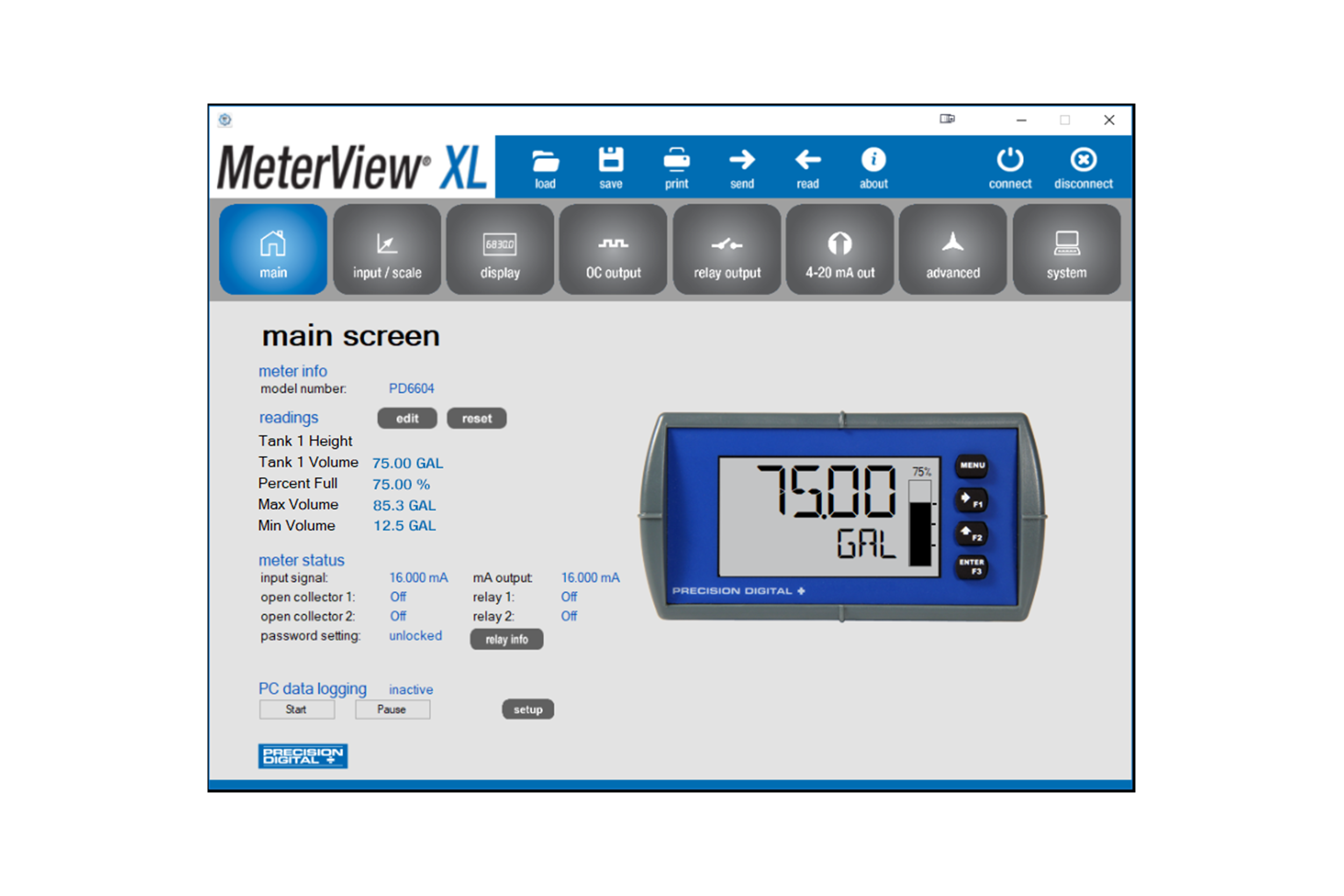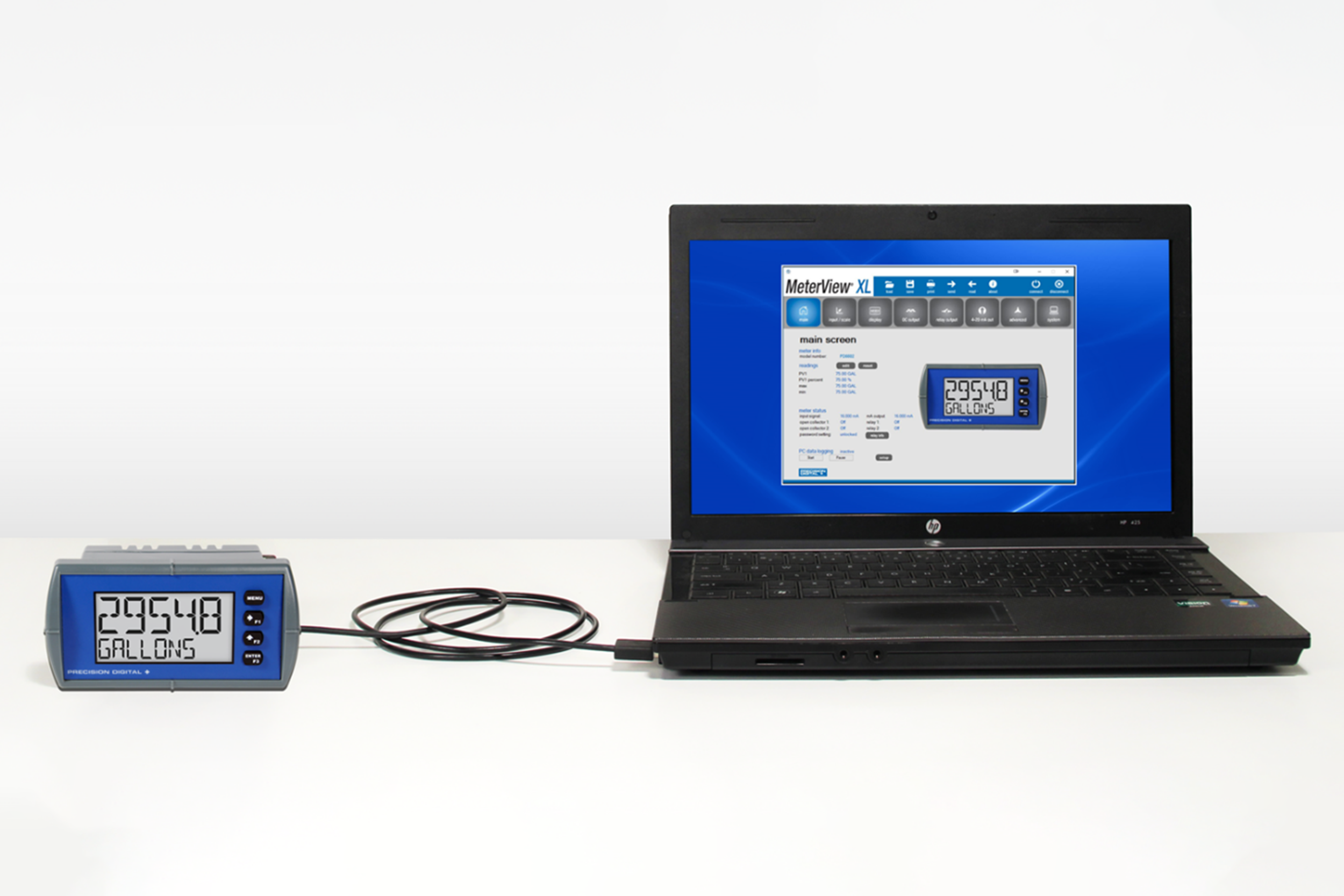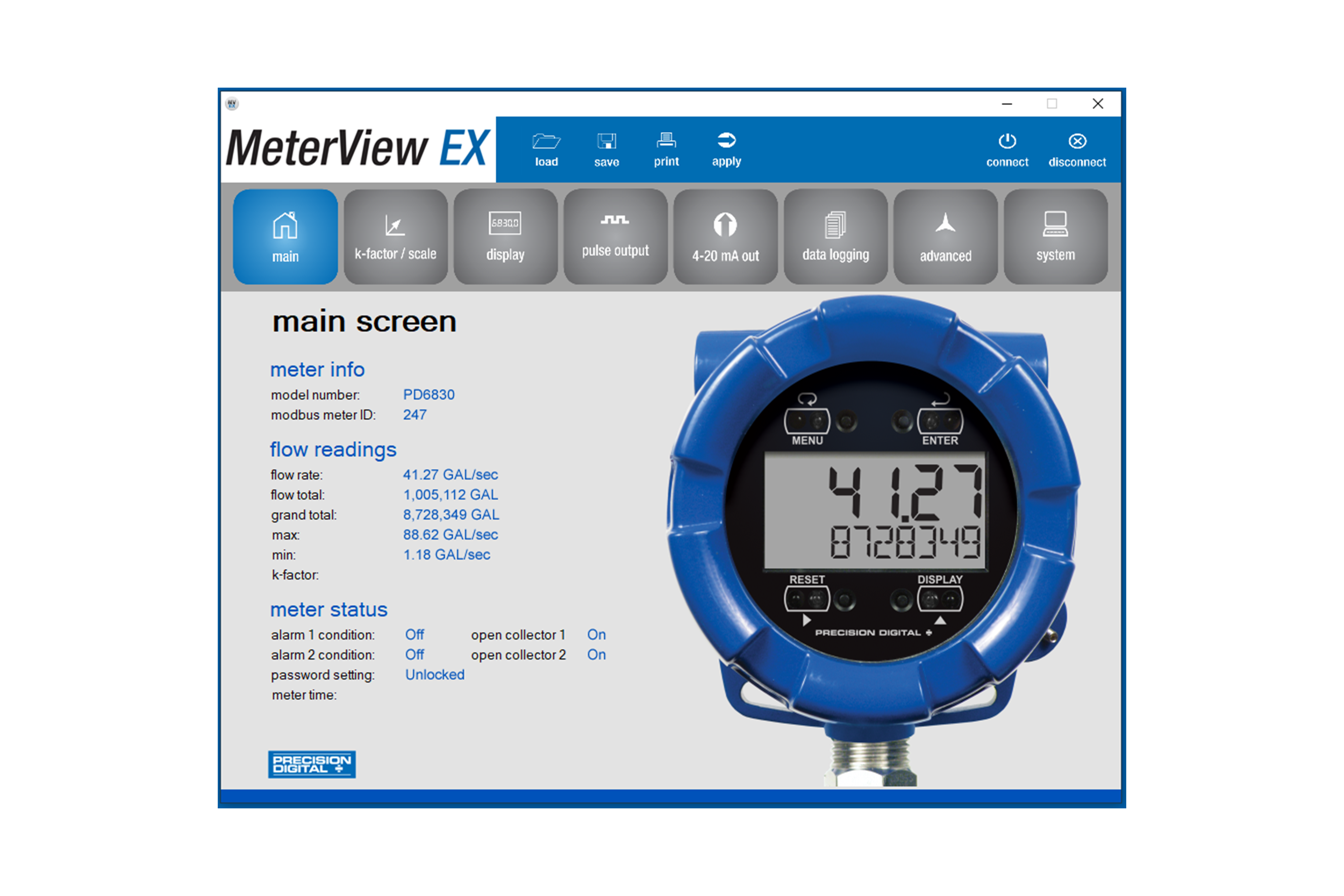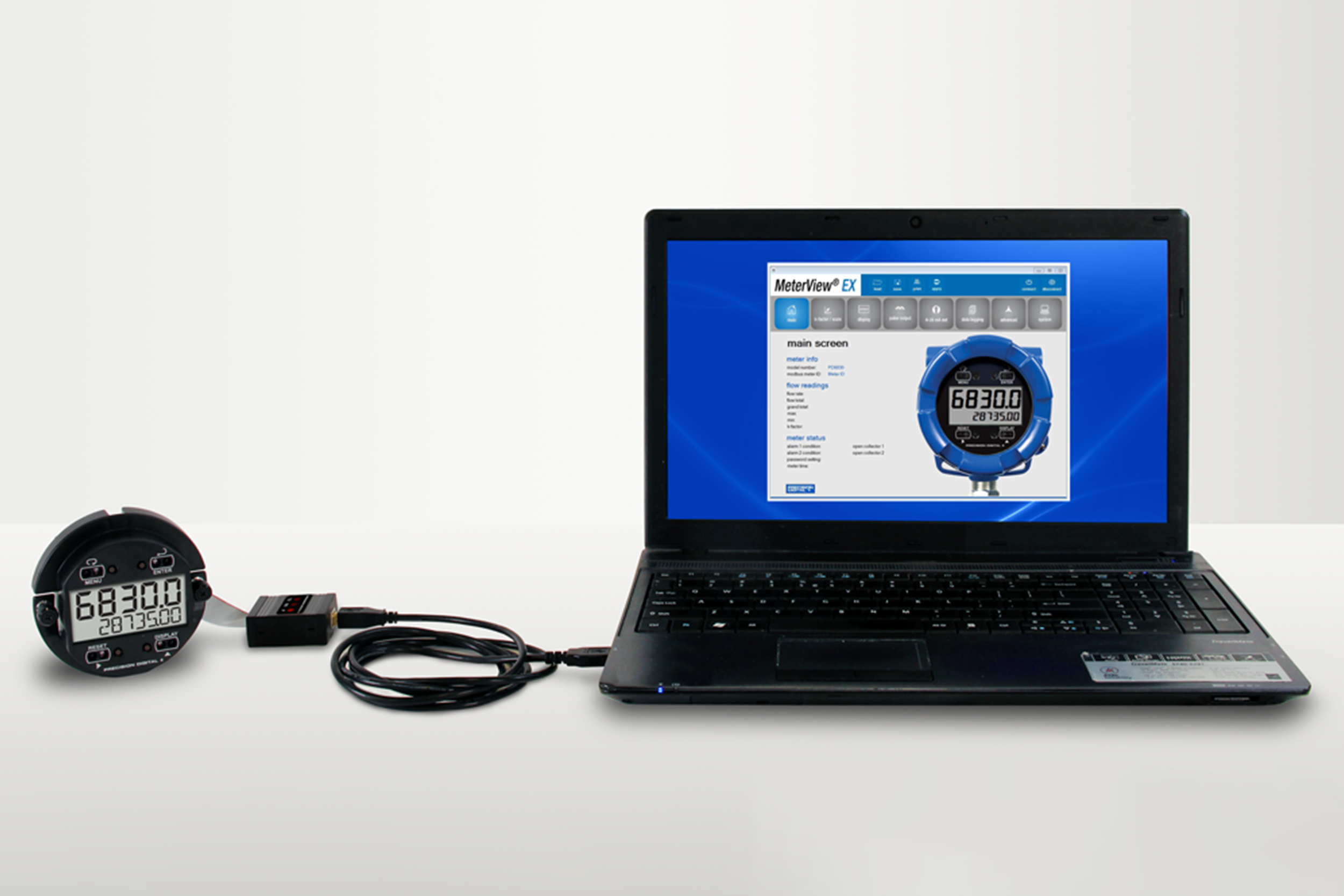


Configure, monitor, or datalog ProVu, Helios, or ProtEX-MAX meters using the PC-based MeterView Pro (MVP) software. MVP is available here as a free download and makes complete meter configuration simple and fast. Copying one meter configuration to another, as well as saving or retrieving a meter configuration file, is a snap. MVP's linearization utility makes even a 32-point linearization task clear and easy to do.
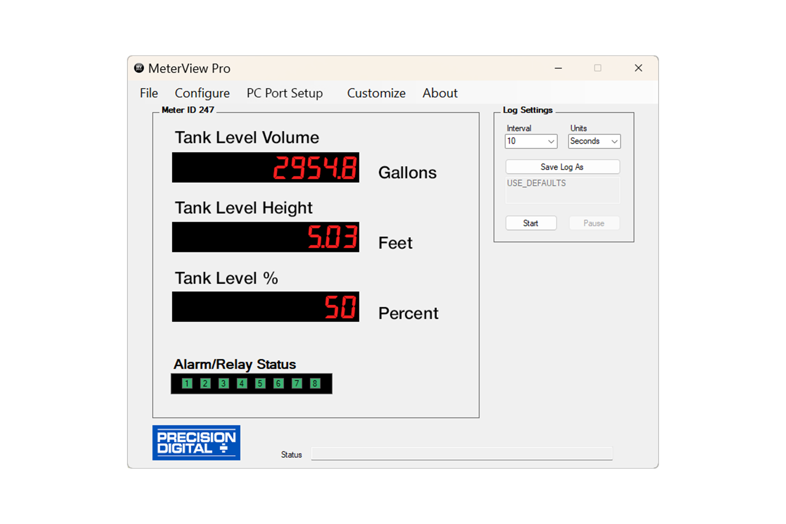
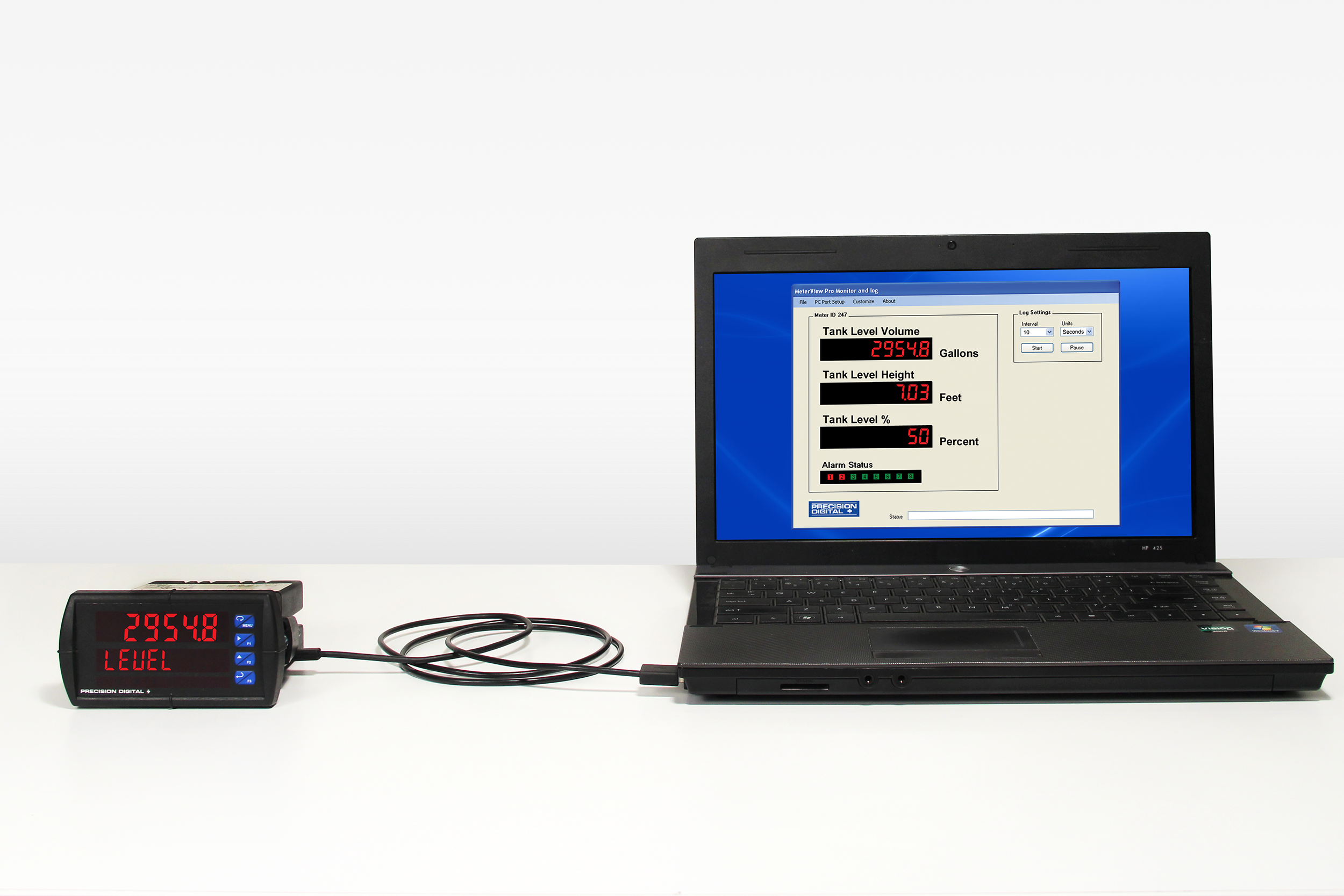
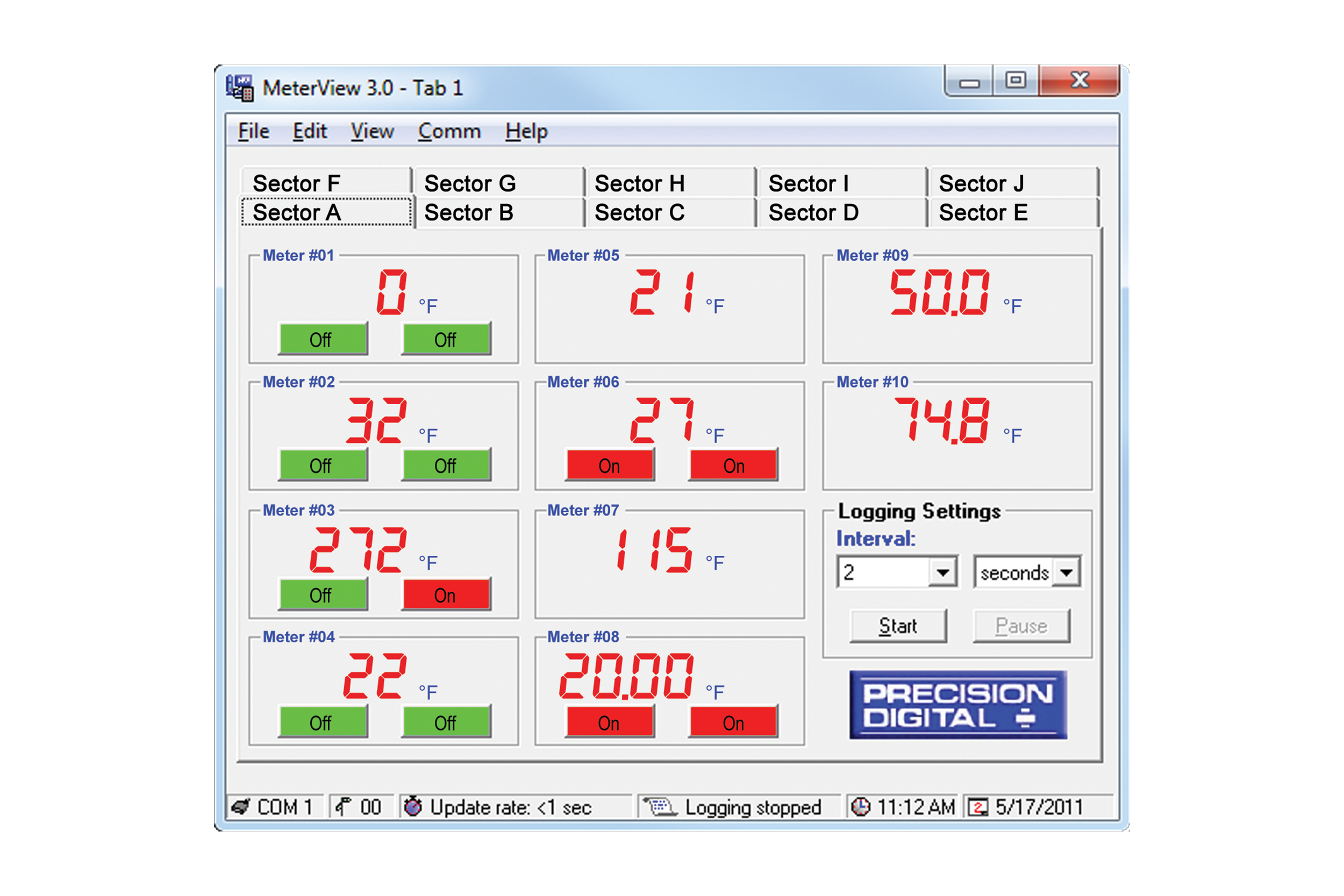
Also included is a basic meter monitor and data logger for use with the meter. Of course, with the inclusion of the powerful Modbus protocol, custom programs can be made even more versatile.