Features
- FREE Download
- Easily Configure PD6730/PD6830 Flow Rate/Totalizers
- Manage Meter Settings
- Download Data Logs
- Set Up K-Factor, Scaling, Tag, Units, & More
- Scale & Configure 4-20 mA & Pulse Outputs
- Save & Load Meter Configurations
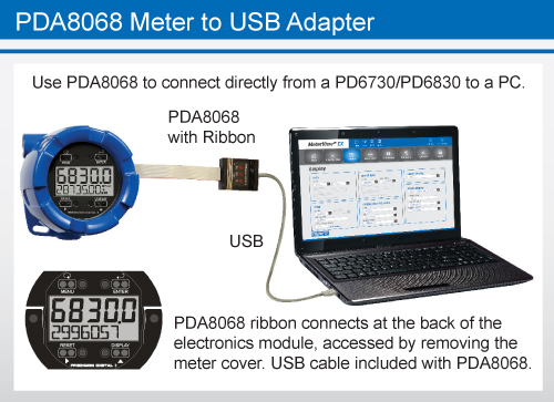
- Easy to Connect with the PDA8068 Meter to USB Adapter
Overview
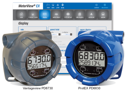
Configure any Vantageview PD6730 Safe Area Meter or any ProtEX PD6830 Explosion-Proof Meter using the PC-based Meterview EX software. Meterview EX is available as a free download (serial communications adapter required). Meterview EX makes complete meter configuration quick and easy. Copying one meter configuration to another, as well as saving or retrieving a meter's configuration file, is a snap. Meterview EX's intuitive layout and easy-to-understand interface make any meter configuration simple to complete. A PDA8068 meter-to-USB adapter is available for a quick & easy PC connection. Meterview EX is an extremely useful tool that eliminates a lot of button pushing and minimizes any confusion when setting up a PD6730 or PD6830.
Connections
WARNING: Observe all safety regulations. Electrical wiring should be performed in accordance with all agency requirements and applicable national, state, and local codes to prevent damage to the meter and ensure personnel safety.
Connection Options
With MeterView EX software, there are a variety of options to connect your Vantageview PD6730 or ProtEX PD6830 meter to a PC for programming, depending on the PC's available hardware.
To connect a PC with a USB connection directly to a PD6730/PD6830, use the PDA8068, a PD6830/PD6730 to USB adapter as seen below. To do so, begin by removing the cover from the meter. Turn the spring-loaded thumb screws on the faceplate counter-clockwise and remove the electronics module from the enclosure carefully. Turn the electronics module over to expose the ribbon connector at the rear. The ribbon connection is made to the connection board of the meter; disconnect the ribbon from the connection board by pushing the connector tabs to the outside. Connect the PDA8068 to the electronics module using the the ribbon connector of each and plug the USB connection into the PC.
Start up MeterView EX software and you are ready to begin programming. Once programming has been completed, simply disconnect the adapter from the electronics module and reconnect the connector board to the electronics module. Screw the electronics module back into the enclosure and put the cover back on the meter.
To connect a PC with an RS-232 connection to a PD6730/PD6830, use the PDA7485, an RS-485 to RS-232 adapter, as seen below. The PD6730/PD6830 must have the -M or -I RS-485 option in order to use a PDA7485. The meter uses a two-wire RS-485 connection. The PDA7485 contains five terminal connections plus a five position DIP switch. The factory settings allow the adapter to work in this configuration. Check the connections, using the the information in the diagrams below, to be sure they are correct. Connect the PDA7485 to the PC using an RS-232 cable. Start up MeterView-EX software and you are ready to begin programming.

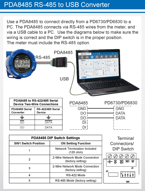
To connect a PC with a USB connection to a PD6730/PD6830 equipped with the RS-485 option, use the PDA8485, a USB to RS-485 converter, as seen below. The PD6730/PD6830 must have the -M or -I RS-485 option in order to use a PDA8485. The meter uses a two-wire RS-485 connection. The PDA8485 contains five terminal connections plus a five position DIP switch. The factory settings allow the converter to work in this configuration. Check the connections, using the the information in the diagrams below, to be sure they are correct. Connect the PDA8485 to the PC using a USB cable. Start up MeterView EX software and you are ready to begin programming. Additional information regarding the use of Precision Digital adapters and converters is available here on our website.
Configuration
With MeterView EX software, it is a simple process to configure your Vantageview PD6730 or ProtEX PD6830 meter. Navigate quickly and clearly through the screens and drop-down menus to set up Units, Displays, Relays, K-factor, Analog Outputs, and more. All variables & alarms can be configured, plus the user may also set parameters for Data Logging. Configurations can be saved as ".mve" files and can be loaded at any time from the MeterView EX folder on the computer's C: Drive: C:\PDC\MeterView EX 1.00\Meter Data. To create configuration files, load the default configuration file, change the settings, then save as a new configuration file. Configurations can also be printed (click Print), and print in list form.
Initial Communications Setup
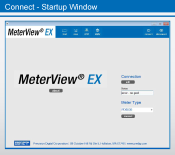
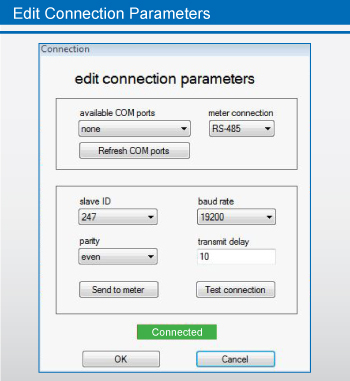
When connecting to a meter using MeterView EX, simply click on the Connect menu or Connection menu edit button in the initial startup window, and the Edit Connection parameters menu appears.
On the left side of the window, there is a drop-down menu of available communication ports. If you don't see your port listed, refresh the COM List. The meter's connection status can be seen at the bottom of the window; a green box indicates that the meter is connected. The user is able to check the connection at any time by pressing the Test Connection button.
The software serial settings are visible in this window. The information associated with each parameter should be entered by the user. The slave ID is the meter's unique address identification. The default slave ID is 247. The baud rate, parity, and transmit delay should match those of the meter being connected to, or communication breaks may occur. Select from the drop-down menu choices.
The user can send the settings to the meter when the information has been entered.
Main Screen
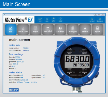
The Main Screen is where the operator can monitor readings from, and status of, a programmed PD6730 or PD6830. The Main Screen is divided into three parts: Meter Info, Flow Readings, and Meter Status.
Under Meter Info, the model number (i.e. PD6830) and Modbus Meter ID are clearly visible at the top left of the screen.
Flow Readings is where the operator will find up to date flow measurement. Measured readouts include flow rate in selected engineering units, as well as total and grand total. For the Maximum Flow reading, see Max; see Min for the Minimum Flow reading. The pulse input may be set up using the K-factor, or conversion factor, function. Most flowmeter manufacturers provide this information with the device. The K-Factor converts input pulses to rate in engineering units. K-factor may be programmed from 0.000001 to 9,999,999 pulses/unit.
The Meter Status section provides information on alarm conditions for two different alarms - Alarm Condition 1 and Alarm Condition 2 - as well as the two different Open Collectors - Open Collector 1 and Open Collector 2.
Password Setting information and Meter Time round out the Main Screen.
K-factor/Scale Screen
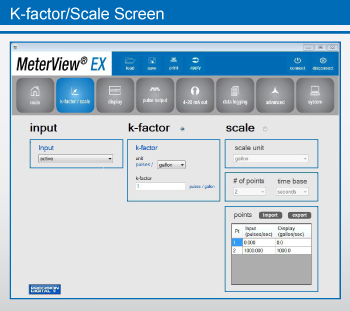
The K-factor/Scale Screen is divided into three parts: Input, K-factor, and Scale. For the Input Menu, the choices are:
- Active
- NPN
- PNP
- Reed
- Coil
- Isolated Active
- Active with Low Threshold
- NPN with Low Threshold
- PNP with Low Threshold
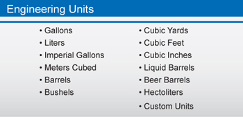
The operator chooses K-factor by clicking on the K-factor button. K-Factor Units - Select the units defined with the K-factor (example: pulses/gal). This is usually provided by the flowmeter manufacturer. This does not set the rate display units, and only relates to entering the K-factor. Engineering Unit choices can be referenced below. The K-factor unit may be a custom unit. Automatic unit conversions are not performed when the K-factor unit is set to custom. K-Factor entry: Set the number of pulses per unit necessary to produce the K-factor value.
Note: The operator can choose either K-factor or Scale, but not both.
The operator chooses Scaling by clicking on the Scale button. Scaling Units are selectable from the drop-down menu. Unit Choices can be referenced below. Choose the number of scale points (from 2 up to 32 points may be selected) and a Time-base: seconds, minutes, hours, or days. Then, enter values for each Input Point in pulses per second, as well as values for each Display Point in Units per time-base (i.e. pulses per second & gallons per minute). Points can be both imported and exported as a ".csv" file, the location of which are stored on the computer's C: drive (C:\PDC\MeterView EX 1.00\Meter Data).
Display Screen
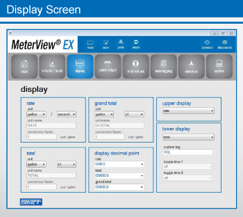
The Display Screen is divided into six sections - rate, total, grand total, display decimal point, upper display, and lower display.
For rate, select a unit of measurement from the Units drop-down menu and a time-base from the drop-down menu. For total and grand total, select a unit of measurement from the Units drop-down menu and a multiplier: x1, x100(h), x1000(k), x1e6(M). For custom units, the unit name and conversion factor are also displayed here.
For display decimal point, select the location of the decimal point from each drop-down menu for rate (four decimal places to none), total, or grand total (six decimal places to none).
The upper display value can be either rate or total, selectable by the drop-down menu. The lower display value, also selectable by drop-down menu, can be set to display:
- total
- total & units
- total & tag
- total & units & rate units
- grand total
- grand total & units
- grand total & tag
- grand total & units & rate units
- rate
- rate & total units
- rate & units
- rate & tag
- rate units
- total units
- custom tag
- off
Two separate toggle times are selectable via drop-down menu, and a custom tag can be entered.
Pulse Output Screen
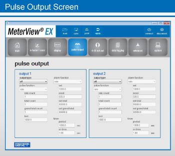
The Pulse Output Screen has two separate sections for controlling the meter's two NPN open collector outputs, Output 1 and Output 2. The category criteria for each output is identical.
Pulse outputs are based on rate, total or grand total counts, or one-for-one retransmit for input pulses, as seen below. Both outputs may be used to generate a quadrature output based on any pulse menu output type, though only one output should be set to quadrature. An output test mode is also selectable to generate pulses at a constant programmable frequency.
Alarms are available based on the rate, total, or grand total. The alarm status will show on the display even if the output is not wired. The outputs may also be forced on or off.
A timed pulse output generates constant pulses at a specified frequency and on time.The output may be disabled by selecting Off.
Output type is selectable from a drop-down menu and can be set to off, pulse, alarm, or timer. Depending upon the selection, various drop-down menus and information fields become available to the operator. Each can be customized by the user to fit the proper application.
Fields include:
- alarm function
- pulse function
- rate count
- total count
- grand total count
- set
- reset
- set total
- test
- set grand total
- timer period
- on time
Pulse & Alarm functions have drop-down menus. Pulse Functions include rate, total, grand total, test, quadrature, or retransmit. Alarm Functions include rate, total, grand total, alarm on, or alarm off.
4-20 mA Output Screen
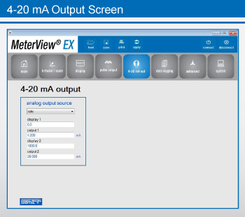
MeterView EX software allows the user to set parameters for scaling the meter's 4-20 mA output. The meter's 4-20 mA output allows the operator to connect to an input device such as a remote display or chart recorder.
The Analog Output source menu is used to program the 4-20 mA output based on display values entered by the operator. The 4-20 mA analog output (if equipped) can be scaled to provide a 4-20 mA signal for any display range selected for either the rate, total, or grand total.
For the analog output source, select from the drop-down menu, choosing either rate, total, grand total, or disable.
The output may be disabled, and will only output the minimum signal. No equipment is needed to scale the analog output; simply program two display values and corresponding mA output signals.
Note: When power is removed from the meter, the analog output will drop below 1 mA.
Data Logging Screen
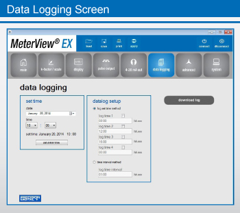
The Data Logging Screen is used to setup and enable the data log functions. The meter may contain up to 1024 records, each containing date, time, rate, total, grand total, and log number. There are two ways to configure the time when a data log is recorded. The Log Set Time Method allows up to 4 data logs to be recorded each day, at specific times. The Time Interval Method allows a data log to be recorded when a time interval has passed.
Only the Log Set Time Method or Time Interval Method may be active at once. While one type of data logging has been enabled, the other menu will be inaccessible.
Log Set Time Method
The Log Time menu contains four log points (Log Time 1 to Log Time 4). Each log time is configured separately. For each daily log time desired, enable a log by checking its box, and set the log time for the hours and minutes the log is to be recorded. The time is set in real-time, based on the real time clock setup.
The Log Time feature will roll-over, deleting the oldest data logs (in blocks of 8) when the log is full and new logs must be recorded. This makes it the most useful for long-term data logging.
Time Interval Method
The Interval menu sets the time interval for data logging. Every time interval, one data point will be recorded. To enable interval data logging, enable the feature by checking its button, and set the interval time for the hours and minutes between each log. The Time Interval Method will not delete old data, and data logging will stop when the log is full. This makes it the most useful for short periods and logging specific functions. The Time Interval Method cannot be used if the data log is full.
Advanced Screen
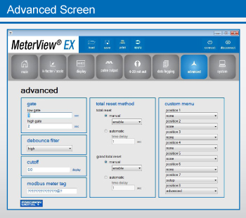
The Advanced Screen is divided into six sections: gate, debounce filter, cutoff, Modbus meter tag, total rest method, and custom menu.
The gate function is used for displaying slow pulse rates. Using the programmable gate, the meter is able to display pulse rates as slow as 1 pulse every 9,999 seconds (0.0001 Hz). The gate function can also be used to obtain a steady display reading with a fluctuating input signal. There are two settings for the Gate, low gate and high gate.
For most applications, low gate setting should be left at 1 second. Increase low gate setting to obtain a steadier rate display. The rate display will update in accordance with the low gate setting, for example if low gate is set at 10, the display will update every 10 seconds; changes in rate between updates will not be reflected until next display update.
Set the high gate value to correspond to the highest expected pulse period (lowest pulse rate). For instance if the meter must display a rate when there is 1 pulse coming into the meter every 10 seconds, set the high gate to 11 seconds. When the signal is removed from the meter, the display will show the last reading for 11 seconds; then it will read zero.
The debounce filter function can be used for applications where the meter is set up to count pulses generated by switch contacts. There are three settings, high speed, medium speed, and low speed.
High speed disables the contact debounce filter and allows any pulse of the minimum specified width for the selected input type. The medium filter ignores signals faster than 250 Hz max, or pulse widths less than 2 ms at 50% duty cycle. The low filter ignores signals higher than 100 Hz, or pulse widths less than 5 ms at 50% duty cycle.
The low-flow cutoff feature allows the meter to be programmed so that the often-unsteady output from a transmitter, at low flow rates, always displays zero on the meter. The cutoff value may be programmed from 0 to 9999.9. Below the cutoff value, the meter will display zero. Programming the cutoff value to zero disables the cutoff feature. The Advanced Screen also features a Modbus meter tag for use in a Modbus network.
There are both manual and automatic settings for the total reset and grand total reset. For manual reset, select whether manual reset will be enabled or disabled. Disabling reset will avoid inadvertent resets of the total/grand total via the front reset button or external reset contact. For automatic reset, enter reset delay time in seconds. Once the output alarm total/grand total set point is reached, the meter waits for a programmed amount of time and then resets the total/grand total to zero.
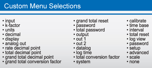
The custom menu section allows the operator to select from a list of choices to cutomize the meter's menu for specific applications. There are up to eight different positions to choose from; see below for a full list of selections for each position.
System Screen
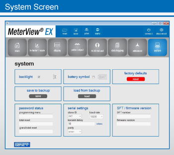
The System Screen allows the operator to enable the meter's backlight, as well as the Battery symbol on the meter's display. Settings can be both saved to and loaded from a backup, or restored to factory defaults.
The password status of the meter can be obtained for the programming menu, the total reset, and grand total reset. Also available is information about the meter's software and firmware versions. The Modbus Slave ID of the meter may be set.
The other serial settings, which are clearly visible, must match those of other devices on a Modbus network in order to avoid any breaks in communication. Changing serial settings may require the software serial settings to be changed in order to reconnect to the meter.
Additional Information
About the Software
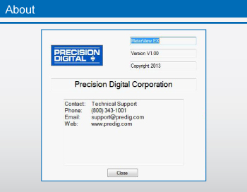
By clicking on the About button in the initial MeterView EX setup window, a popup window will appear displaying the version of MeterView EX installed. Also appearing in the window is both general and technical support contact information for Precision Digital Corporation.
Precision Digital Adapter & Converters
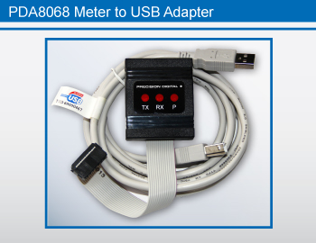
For quick and easy configuration of your PD6730 or PD6830, use the PDA8068 Meter-to-USB adapter, which will work with all models of the meters.
For models with the RS-485 option installed, use the PDA7485-N or PDA7485-I RS-232 to RS-485 converter for an RS-232 connection; or use the PDA8485-N or PDA8485-I USB to RS-485 converter for a USB connection.
PDA8068 comes with a USB cable. PDA7485 does not come with an RS-232 cable; a standard RS-232 cable may be used.
PDA8485 does not come with a USB cable; a standard USB cable may be used.
Load or Save Any Configuration
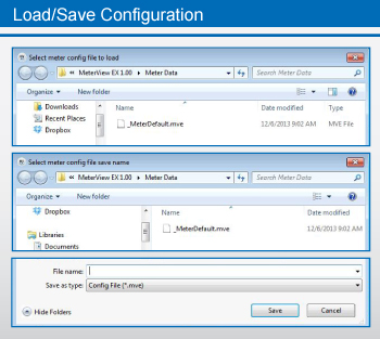
Configurations can be saved as ".mve" files and can be loaded at any time from the MeterView EX folder on the computer's C: Drive.
C:\PDC\MeterView EX 1.00\Meter Data
To create configuration files, load the default configuration file, change the settings, then save as a new configuration file.
Specification
System Requirements: Windows® 2000/XP/Vista/7/8 (Windows 32-bit or 64-bit operating systems). Communications: All models: PDA8068 Meter-to-USB adapter. For models with RS-485: (PDA7485-N or PDA7485-I) RS-232 to RS-485 converter; or (PDA8485-N or PDA8485-I) USB to RS-485 converter. PDA8068 comes with a USB cable. PDA7485 does not come with an RS-232 cable; a standard RS-232 cable may be used. PDA8485 does not come with a USB cable; a standard USB cable may be used. Meter Address: 1-247 Reports: Data logging: Save as ".csv" file format Configuration: Save as ".mve" file format or print configuration Baud Rate: 1200 bps to 115,200 bps Configuration: Configure scanner settings one scanner at a time. Data Logging Report: Save as CSV file format. Configuration: One meter at a time. Protocol: Modbus RTU (Slave)The Information contained in this document is subject to change without notice. Precision Digital Corporation makes no representations or warranties with respect to the contents hereof, and specifically disclaims any implied warranties of merchantability or fitness for a particular purpose.