
Features
- Resident on ProVu, ProtEX-MAX, and Helios Series Modbus Scanners
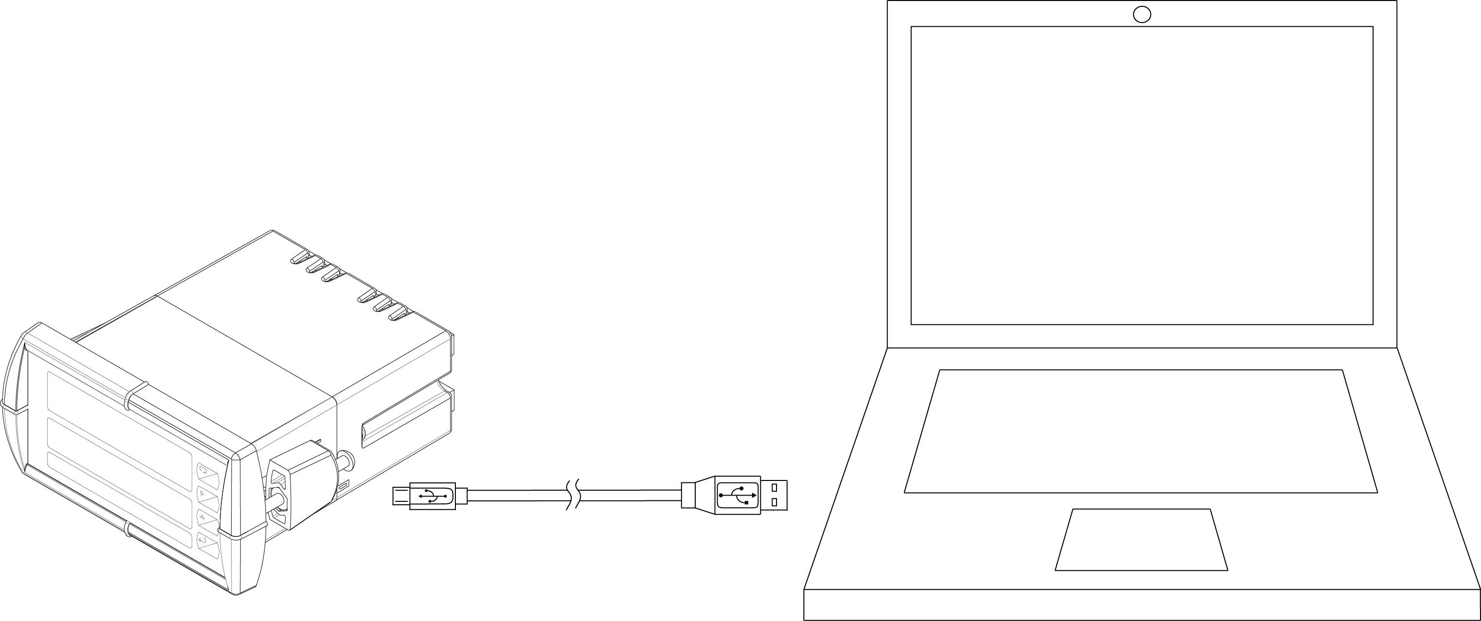
- Convenient USB Installation
- Use in Modbus® Master, Slave, or Snooper Mode
- Scan up to 16 Modbus Process Variables
- Easily Configure Super Snooper Modbus Scanners
- Manage Scanner Settings
- Monitor Critical Process Information
- Program and Display the Four Math Channels
- Manage Relays and Analog Outputs
- Independent Scaling, Tag, and Unit for Each PV
- Modbus RTU Serial Communications via RS-485
- Data Log all PVs to a PC
- Important: Please uninstall previous versions of this software first, before downloading and running the latest version.
Overview
Configure, monitor, or datalog any ProVu, ProtEX-MAX, or Helios Series Modbus Scanner using the PC-based ScanView software. All ProVu, ProtEX-MAX, and Helios Series Modbus Scanners now come preloaded with the free ScanView software and includes a standard USB cable. This makes is fast and simple, and eliminates the need to install drivers and download from the internet. Just connect the meter to the PC with the USB cable and you'll be up and running in no time! ScanView's linearization utility makes even a 32-point linearization task clear and simple to complete. We also included a basic scanner monitor and datalogger. Of course, with ProVu's, ProtEX-MAX's, and Helios' powerful Modbus protocol, custom programs can be made even more versatile. ScanView is an extremely useful tool that eliminates a lot of button pushing and minimizes any confusion when setting up one of these scanners.
With ScanView software, it is easy to configure and monitor any ProVu, ProtEX-MAX, or Helios Series Modbus Scanner. Navigate quickly and clearly through the tabs and drop-down menus to set up Scan Mode, Process Variables (PVs), Displays, Relays, Math Channels, Analog Outputs, and Function Keys. Monitoring data from the scanner is just as simple: All enabled PVs, Math Channels, Alarms, Scan Status, Data Logging Status, etc., populate the Monitor window. The user may also start/stop scanning and set parameters for Data Logging. From the Monitoring window, the operator can get to the Configure, Customize, About, and Connection windows.
Installation of ScanView software is required for technical support services to be provided for ProVu, ProtEX-MAX, or Helios Super Snoopers Modbus Scanners.
Configuration Steps
Initial Communications Setup
For initial scanner configuration, ScanView software can be installed on any Microsoft® Windows® (XP/Vista/7/8/10) computer by connecting to the meter's onboard USB. The meter is powered by the USB connection, so there is no need to wire anything prior to programming the meter, though USB is intended only for meter configuration.
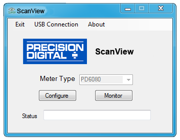
After ScanView is installed, it should automatically detect what kind of meter is connected. Simply click the Configure or Monitor button to continue.
When connecting to a Modbus network using ScanView, simply click on the Connection menu in the initial setup window, and the Serial Setup menu appears. On the left side of the window, there is a drop-down menu of available communication ports. If you don't see your port listed, refresh the COM List. The scanner's connection status can be seen at the bottom of the window; a green box indicates that the scanner is connected. The user is able to check the connection at any time by pressing the Check Connection button. The meter serial settings are visible on the right side of the window. The information associated with each parameter should be entered by the user. The meter address is the scanner's unique identification. The default meter address is 246. The baud rate, parity, transmit delay, and character timeout should match those of other devices on the bus, or communication breaks may occur. The user can write the settings to the meter when the information has been entered. The settings can also be made the default settings from this window, to make reconnecting even easier, as seen below.


Configure Tab: Modbus Scan
The Modbus Scan Tab is used to set the scanner mode to either master, snooper, or slave. Next, enter the Poll & Response times. The Poll Time should be set for five (5) seconds or more when using ScanView.
The Display Scan can be set to Automatic or Manual and can be configured to either Go On Alarm or Stop On Alarm. The Scan Time is set by the user.
Each PV can be enabled and configured from its tab on the right side of the window. Parameters include Slave ID (unique address assigned to the PV from 1-247, or 256-259 for on-board current or voltage inputs), Function Code, & Slave Register Number (includingsix-digit setting). Data Settings include Data Type (short or long binary or BCD & signed or unsigned, or float) and Byte Order (big endian, little endian, or swapped).

Configure Tab: Setup 1
The Setup 1 Tab is used to set up the Modbus Scan Settings for each enabled PV or Math Channel (Math Channels must first be turned on in the Advanced Features 1 Tab).
The user-entered information includes the Tag, Unit, Display Format (Decimal, 1/8 Inch, or 1/16 Inch), Display Decimal Point, and Floating Decimal Point.
Scaling of individual PVs also takes place in this window. The user enters both the input and display scale points. There are 32 linearization points available for PVs 1 & 2, while all other PVs have two linearization points. Linearization tables can be both imported from and exported to Microsoft Excel.

Configure Tab: Setup 2
The Setup 2 Tab is used to set up both the upper (Main) & lower (Small) displays via their independent drop-down menus.
The Main Display choices are: PV, Math, PV/Unit, Tag/PVn, Tag/PVn/Unit, Math/Unit, Tag/Math/Unit, Relay 1-4 SP, Max PV, Min PV, Max Math, & Min Math. The Small Display choices include all those from the Main Display, plus Tag, Tag/Unit, & Off. The selectable Display Intensity ranges from 1-8, with 8 being the brightest setting.
The Manual Control Menu is used to control the analog output, the Relay Force On (check the desired relays), and the Digital Output Force On (visible only when DO module connected). The Auto button is green when the scanner is in Automatic operation, and yellow when the scanner is in Manual operating mode.
The firmware revision number displays in the Information box.

Configure Tab: Relays
The Relays Tab is used to set up the scanner's relays. The scanner comes equipped with four relays standard, but expansion modules allow for up to eight relays (visible only when module is connected).
Each relay can be assigned to any of 16 PVs, Math Channels, or multiple PVs. Relay Action is set according to the following parameters: Auto, Auto w/Manual Reset, Latching, Latching w/Clear, Pump Alternate, Sample, or Off. The set & reset points for each relay are entered according to the Display Format. For Feet & Inches, use a comma to denote the separation of feet, inches, & either eighths or sixteenths of an inch (1,6,0).
If the user selects Sample as the Relay Action, the Sample time (in seconds) is entered in the appropriate box.
The user also enters any desired time delay in the On Delay & Off Delay boxes. The scanner's Fail Safe feature can be switched on or off. The Input Break menu sets the input break conditions: On, Off, or Ignore. Each relay is programmed independently.

Configure Tab: Advanced 1
The Advanced Features 1 Tab is used to enable the display rounding feature, configure Math Channels, scale the results, define the signal input conditioning features, and set the PV filter settings.
The General Settings box contains parameters for the Rounding Feature, used to round readings to the nearest 1, 2, 5, 10, 20, 50, or 100 (this setting affects the last three digits, regardless of decimal point position). These settings are user-selectable from the dropdown menu.
Each Math Channel is set up in its own tab within the Math box. The user-entered info includes the adder and factor constants. The Math Function can be selected from the drop-down menu; choices include: sum, difference, absolute difference, average, multiplication, division, maximum & minimum PVs, draw, weighted average, ratio, concentration & Math2. The Math2 feature can be used to run additional calculations on Math Channels. However, Math2 functions, which will appear in a separate drop-down menu, are limited to sum, difference, absolute difference, average, multiplication, and division. Once the math function has been selected, simply check off the PVs or Math Channels to be used for calculation.
For Signal Input Conditioning, just select the desired PV, then select the appropriate choice from the drop-down menu: Linear, Square Root, Programmable Exponent, and Round Horizontal Tank (RHT). For Programmable Exponent, enter the desired value in the Exponent box. For RHT, enter the length and width of the tank. The default unit of measurement is inches; for centimeters, simply check the CM box and plug in the numbers.
The Math Channels in the Signal Input Conditioning box have the capability of performing the Linear and Square Root functions, selectable from the drop-down menu. The Filter Settings are used, primarily with the Analog Input Channels, to help attain a steady display with unsteady (noisy) data. Increasing the filter value will steady the display, and can be set anywhere from 2-199. Setting the filter value to zero disables the filter function.
The Bypass Value allows larger input signal changes to be displayed immediately by bypassing the noise filter's averaging capability. The Bypass Value can be set anywhere from 0.2 to 99.9. The Cutoff Value allows the scanner to be programmed so that the often unsteady output from a differential pressure transmitter, at low flow rates, always displays zero. The Cutoff Value may be programmed from 0 to 999999. Using a zero value will disable the Cutoff Feature. This feature is used with PV1, PV2, and the analog input channels.

Configure Tab: Advanced 2
The Advanced Features 2 Tab is used to enable and configure the installed Analog Outputs, Function Keys, Digital Inputs, and Digital Outputs.
The Analog Out Control box contains tabs for each output, which can be programmed for source of data, overrange & underrange, absolute maximum & minimum output, and communications break values. They can also be recalibrated, which is done by entering the appropriate scaling information in the Display Value and Output Value boxes.
For decimal format, enter the Display Values as decimal numbers, while Feet & Inches format requires the user to enter each Display Value segment separated by a comma. For example, if the display format is in Feet & Inches with eighths or sixteenths of an inch selected, the Display 1 Value would be 4,0,0 and the Display 2 Value would be 20,0,0 for scaling of a 4-20 mA signal. The source can be any of 16 PVs, 4 Math Channels, or 4 Set Points. The Break Value determines the mA output when a Slave fails to reply to a command within the Response Time. To ignore any break conditions, simply uncheck the Break Checkbox.
The overrange and underrange values are the values that will be output when the display shows an underrange or overrange condition. The maximum and minimum values are the absolute limits for the 4-20 mA output.
The User Menu is where the Function Keys, Digital Inputs, & Digital Outputs are configured (Digital Inputs & Outputs will only display if the expansion modules are installed). Each Function Key can be assigned a parameter, the choices being: Acknowledge, Reset Menu, Reset Max, Reset Min, Reset Max/Min, Relay, Set1-Set4 (there are up to eight Set Points available), Relay Disable, Relay Enable, Output Hold, Display Hold, Disable, Control Menu, Scan Start/Stop, Display Next, and Display Previous.
For installed Digital Inputs, the parameters are: Menu, Right, Up, Enter, F on 1 (all installed relays can be forced on, up to eight), Control, Scan, Next, Previous, Acknowledge, Reset, Reset Max, Reset Min, Reset Max/Min, Relay, Set1-Set4 (there are up to eight Set Points available), Relay Disable, Relay Enable, Output Hold, Display Hold, and Disable.
For installed Digital Outputs, the parameters are: Alarm (there can be up to eight alarms), Acknowledge, Reset Max, Reset Min, Reset Max/Min, and Disable. The scanner can be reset to the factory default settings by simply clicking on the Reset Meter Factory Defaults button.
Once the user has entered all desired values throughout the tabs in the configuration window, it is necessary to click Send Meter Data to transfer all parameters to the scanner. The configuration can be saved by selecting File-Save Configuration from the top menu bar. Configurations can then be loaded or printed, the defaults can be loaded or saved, and the meter type can be changed from the File Menu.
Features

Feature: Load Configuration
ScanView software is installed on the user's computer C: Drive by default. Configuration files are stored within the Meter Data folder. The default location for Scanview's Meter Data folder is at the location:
Computer - OS (C:) - Program Files (x86) - PDC - ScanView 1.0- Meter Data.
The exact file path will vary based on operating system and any changes to the default location of the ScanView install files. The Configuration files are labeled with the default suffix ".MVP". The file name may also include the Scanner Type (i.e. PD6080).
The Configuration files can be retrieved by simply double-clicking on the desired configuration. Once this is done, all parameters in the Configuration window will be populated. The user clicks the Send Meter Data button to send the configuration to the scanner.

Feature: Save Configuration
The entered configuration may be saved as a Configuration file to the Meter Data folder on the C: Drive. The Configuration files can be custom labeled to include more detail about each configuration. It is imperative that the user be aware that Configuration files can be written over, so renaming new configurations is recommended after instituting changes to the scanner's configuration.
After saving the Configuration file, be certain that the data is sent to the scanner to ensure desired operation. The data file and its status can be viewed in the gray boxes at the bottom of the Configuration window.
It is also possible to import the scanner's existing settings into ScanView by clicking the Get Meter Data button at the bottom righthand side of the Configuration window.
The user can quit the ScanView program at any time by clicking the Exit button at the bottom right-hand side of the Configuration window.
Monitoring Window

Monitoring Overview
Once the scanner has been configured, the user chooses Monitor from the top menu bar. The Monitor window will appear; the enabled PVs and all associated values will take a few seconds to display.
The PVs will display as configured - either in Decimal or Feet & Inches format. Data Logging, Scanning, and Alarm Status can all be viewed at the bottom of the Monitor window.

PV Customization
ScanView software allows the user to customize the display to his/her desired appearance. This is useful, since there can be up to sixteen enabled PVs or Math Channels showing at one time in the Monitor window.
The user is able to use color, custom label, name the group, add or subtract PVs, use custom tags or units, set defaults, and load or save custom files. The first thing to do is to select Customize from the top menu bar.

User Selectable Tags & Units
With the Customize feature, the user is able to input custom tags and units that will help them identify the displayed information. In the Custom Display and logging window, enabled PVs and Math Channels (or none) can be selected via the drop-down menus for each on the left-hand side of the window.
Setting a PV to None will cause it to disappear from the list.
A custom tag may be added in the PV's Tag box, and a custom unit of measurement, such as Gallons, may be added in the PV's Units box.

Add a PV or Math Channel
Easily add a PV by selecting the desired PV from the Add dropdown menu on the bottom left column of the Customize window.
PVs 1-16 and Math Channels 1-4 can be added.
The added PV stays at the bottom of the list until a new PV or Math Channel is entered.

Color for Clarity
ScanView software allows the operator to customize the display by using colors to separate and clarify information for easy identification.
The user just needs to click on the color box adjacent to the PV to be customized, which brings up a color pallette. The user then selects the desired color from the palette and clicks OK to return to the Customize window.
Clear All
To clear all PVs and Math Channels from the Custom Display and Logging window, it is a simple matter of clicking on the Clear All button at the bottom.
All information disappears from the window except the option to Add PVs and Math Channels. The user can then add new PVs, Math Channels, custom tags, custom units, and custom colors to create a new custom file.

Set Defaults
Set the scanner back to the default settings by clicking on the Set Defaults button.
As seen in the graphic to the right, the default settings list all PVs, 1-16, and all Math Channels, 1-4, as well as the default Tag and Unit for each. The default tags are PV1-PV16 for the PVs and C1-C4 for the Math Channels.
Custom Name PV
Give each PV or Math Channel a custom name to simplify identification. The name given to the PV's Tag, such as Sum, displays in the upper left corner of the specific PV's section of the Monitor window as seen in the graphics below (PV1-PV4/Sum/AVG).


Save Custom File
Save any custom file created with ScanView software. ScanView custom files are saved on the computer's C: drive by clicking on the Save Custom File button. Follow the path:
(C:) - Program Files (x86) - PDC - ScanView 1.00.
Custom files are named with the suffix ".svc". It is recommended that the file be saved with a unique name and the date in order to avoid overwriting any custom files. The Group Title can also be customized.

Load Custom File
It is possible to save multiple custom files to call up for future use. The custom file library may be accessed at any time by clicking on the Load Custom File button at the top of the Customization window. The user must follow the path to the Custom Files:
(C:) - Program Files (x86) - PDC - ScanView 1.00.
Any custom file previously created can be loaded into the program by either double-clicking on it or by clicking on it and selecting Open. Once the Custom File has been loaded into the Customize window, simply click the Set button to save changes and exit to the Monitor window.
Data Logging
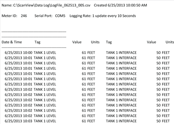
ScanView software allows the user to log data and generate reports. First, select Monitor - Stop Scan from the top menu bar. To log data, select the Data Log drop-down menu from the top menu bar. The parameters for Data Logging appear: Interval, Units, Log File Name, and Start/Pause. For Interval, the choices are from 1-60, while the Unit choices for logging data are Seconds, Minutes, and Hours. The user must then name the Data Log File; it is recommended that the file be saved with a unique name and the date, such as: "ScanView_1.00_Log_X_100813".
Once the Log File has been named, select Monitor - Start Scan from the top menu bar, then select Data Log - Start from the top menu bar. Once Data Logging has begun, the Configure, Customize, and Connection screens cannot be accessed until the user has paused Data Logging. The log file can be retrieved at any time by following the path:
(C:) - Program Files (x86) - PDC - ScanView 1.00 - Data Log.
Data Log files are saved in the Data Log folder as ".CSV" files. To view Data Log files, the user must first pause both Scanning and Data Logging. Data Logging & Scan Status can be seen at the bottom of the Monitor window.
Tips for Operation
- When programming scanner to display different PVs on top & bottom displays, press PREV or NEXT button on scanner when scanning starts in order to sync the displays.
- ScanView can configure, but cannot change ScanID, on the fly.
- Baud Rate, Parity, Transmit Delay, & Char Timeout of Modbus devices must match or communication breaks may occur.
- Feet & Inches format programming uses commas to separate digits, i.e. 4,6,9 would mean 4 feet, 6 and 9/16 inches.
About the Software
By clicking on About in either the Configuration or Monitor windows, a popup window will appear displaying the version of ScanView installed. Also appearing in the window is both general and technical support contact information for Precision Digital Corporation.
Installation of ScanView software is required for technical support services to be provided for Provu Super Snoopers.
Specifications
System Requirements: Microsoft® Windows® XP/Vista/7/8/10Communications: Onboard USB (firmware version 2.0 or higher), RS-232 Adapter, or RS-485 Adapter
Meter Address: 1-247
PV Slave ID: 1-247, 256-259 for on-board Current & Voltage inputs
Baud Rate: 300 bps to 19,200 bps; selection must match the baud rate selected in the meters.
Screen Update Rate: Dependent on system and scanner settings.
Configuration: Configure scanner settings one scanner at a time.
Data Logging Report: Save as CSV file format.
Configuration Report: Save as MVP file format or print configuration.
Protocol: Modbus RTU.
The Information contained in this document is subject to change without notice. Precision Digital Corporation makes no representations or warranties with respect to the contents hereof, and specifically disclaims any implied warranties of merchantability or fitness for a particular purpose.