- CSA, ATEX and IECEx Certified Explosion-Proof Meter
- 4-20 mA, ± 10 V, TC & RTD Field Selectable Inputs
- Full 4-Digit Display, 1.20" (30.5 mm)
- CapTouch Through-Glass Button Programming
- Display Mountable at 0°, 90°, 180°, & 270°
- Isolated 24 VDC @ 200 mA Transmitter Power Supply Option (AC powered meters only)
- 2 Relays + Isolated 4-20 mA Output Option
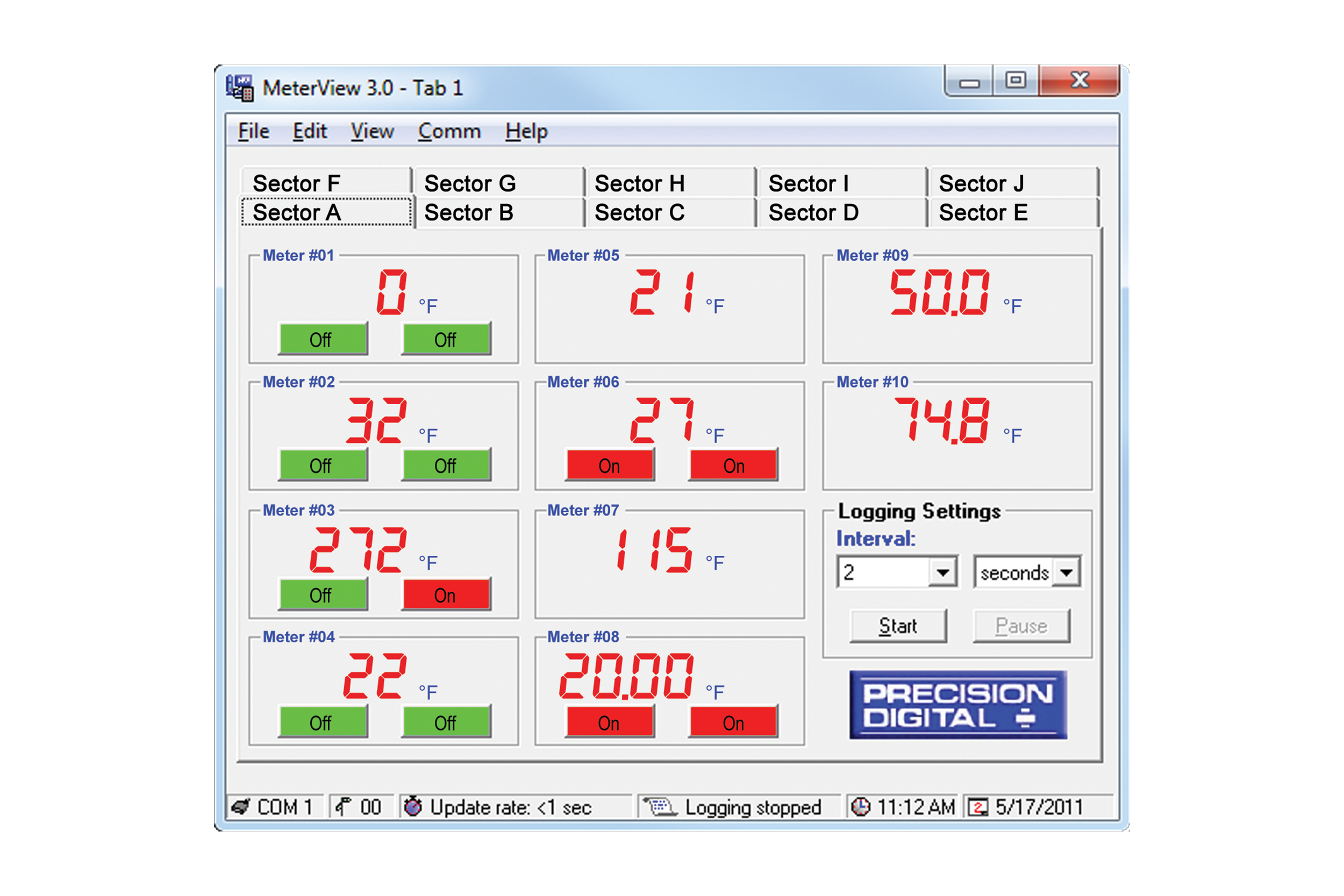
- Free PC-Based MeterView Programming & Monitoring Software
- Sunlight Readable Display
- Operating Temperature Range: -55 to 65°C (-67 to 149°F)
- CSA Certified as Explosion-Proof / Dust-Ignition-Proof / Flame-Proof
- ATEX and IECEx Certified as Dust-Ignition-Proof / Flame-Proof
- Input Power Options: 85-265 VAC / 90-265 VDC or 12-36 VDC / 12-24 VAC
- Duplex Pump Controller with Alternation Capability
- External Contacts for Remote Button Operation
- On-Board RS-485 Serial Communications
- Modbus® RTU Communication Protocol Standard
- Copy Meter Settings to Other PD8-765 Meters
- Password Protection
- Max/Min Display
- High & Low Alarms with Multiple Reset Actions
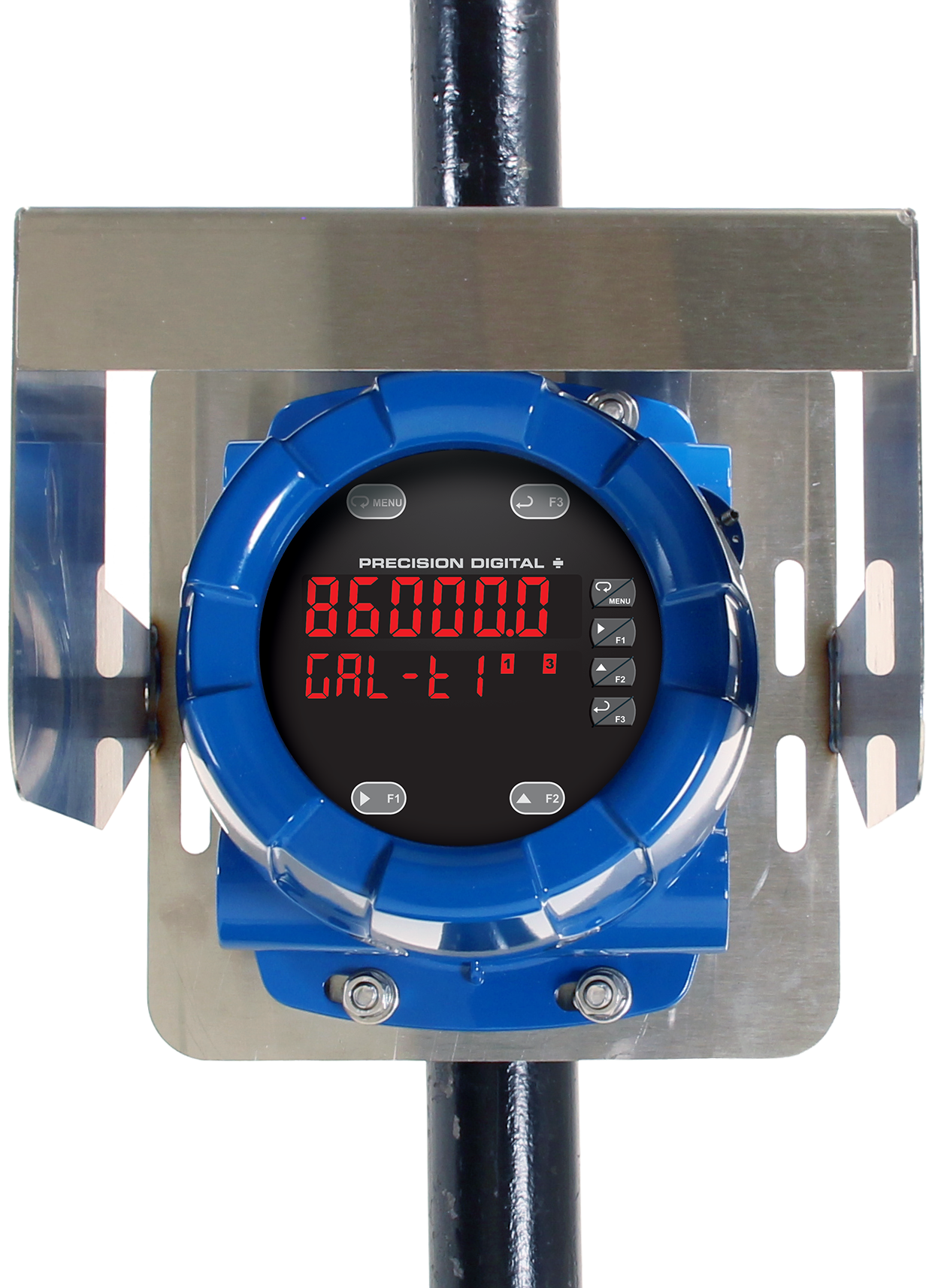
- Flanges for Wall or Pipe Mounting
- Explosion-Proof Aluminum or Stainless Steel NEMA 4X / IP68 Enclosures
- Four 3/4" NPT Threaded Conduit Openings
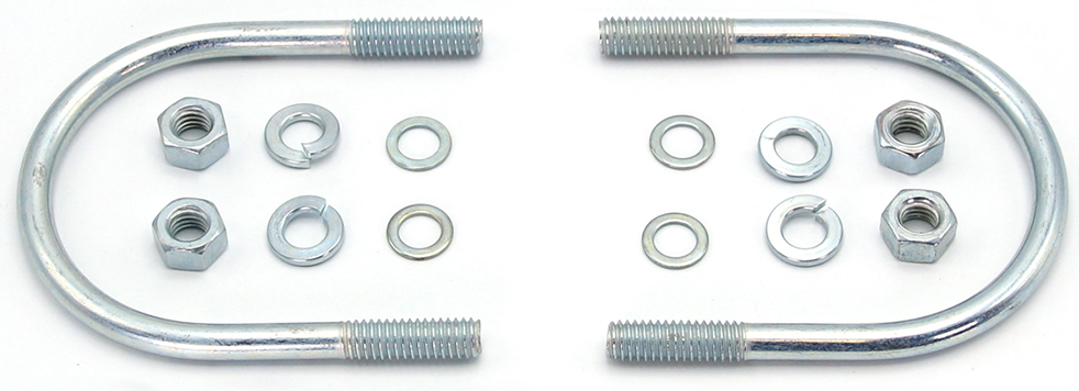
- Stainless Steel Pipe Mounting Kit
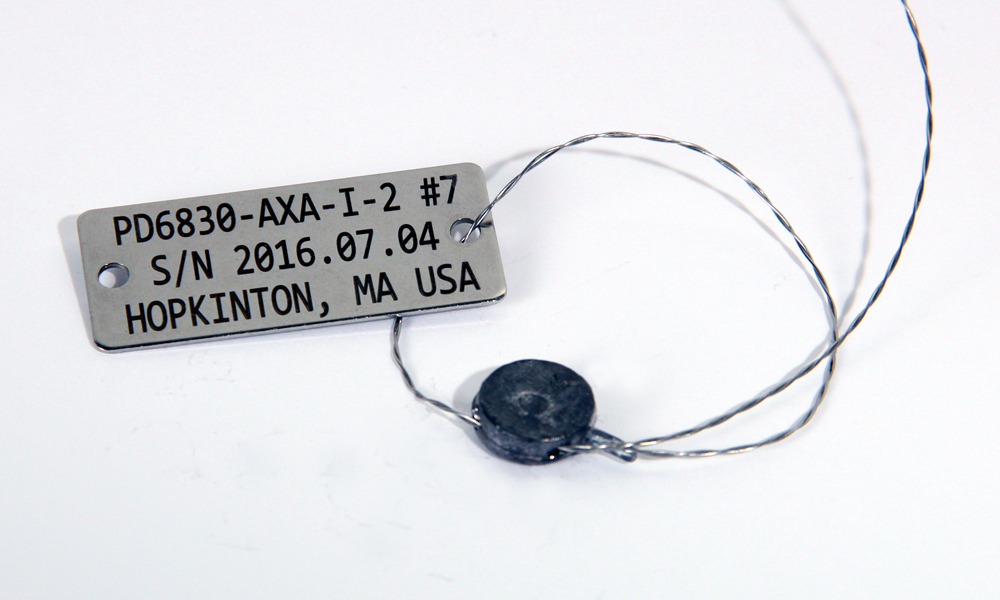
- Stainless Steel Tag Available
- 3-Year Warranty
** NEW IMPROVED WEB STORE! | All users must register for a new account. | Register now > **
BUY ONLINE TO SAVE TIME AND INCREASE ORDER ACCURACY!

Questions? (508) 655-7300
ProtEX-MAX Explosion-Proof Process and Temperature Meter
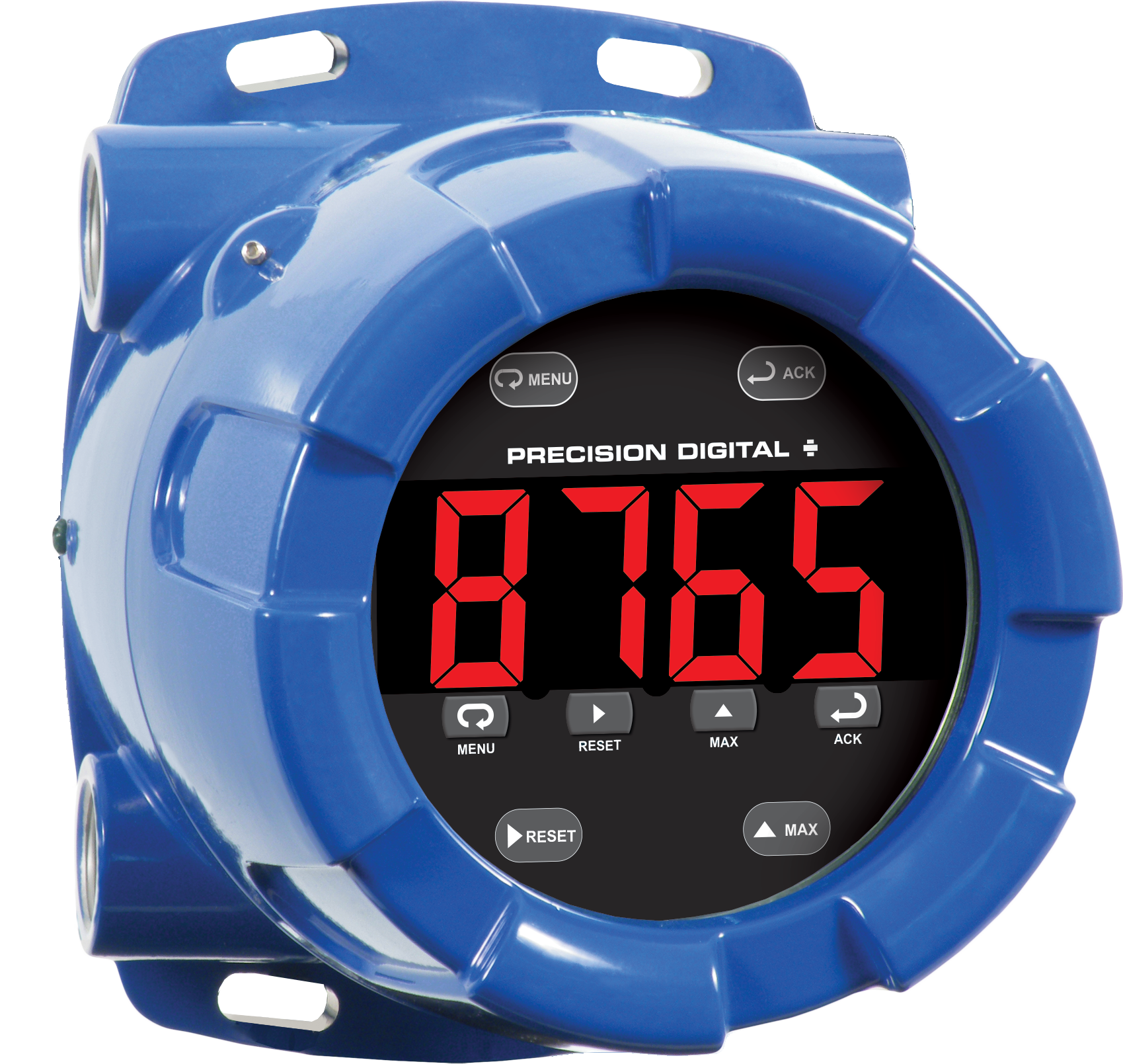
PD8-765 in Aluminum Enclosure


Models in stock
from $1558.00
The ProtEX-MAX PD8-765 explosion-proof, large-display, process and temperature meter offers all the functionality of the Trident X2 as a CSA, ATEX, and IECEx certified explosion-proof product. It is available in an aluminum or stainless steel enclosure and will operate over a wide temperature range of -55 to 65°C (-67 to 149°F). PD8-765's huge 1.2" (30.5 mm) sunlight readable display that is visible from over 30 feet away. This explosion-proof indicator can be field programmed to accept process voltage (0-5 V, 1-5 V, etc.) and current (4-20 mA) inputs, 100 Ohm RTDs, and the four most common thermocouples. The intensity of the display can be adjusted to compensate for various lighting conditions, including direct sunlight. The meter can be programmed and operated without opening the housing by using the built-in CapTouch through-glass buttons or the RS-485 serial communication port with free Modbus protocol. Options for the PD8-765 process and temperature indicator include 2 relays, a 4-20 mA output, and a 24 V transmitter power supply.
Why Should You Buy:
- Big Display
- Worldwide Explosion-Proof Approvals
- Universal Inputs