

Features
- Large Display NEMA 4X, IP65 Loop-Powered Wall & Pipe Mounted Flow Rate/Totalizers
- 4-20 mA Input Displayed with ±0.02% FS Accuracy
- 2.1 Volt Drop Maximum
- 2.8" (71 mm) 5 Alphanumeric 14-Segment Characters Top Display
- 1.5" (39 mm) 8 Alphanumeric 14-Segment Characters Bottom Display
- 20-Segment Bargraph with Numeric Percent Indication
- 8-Digit Total & Grand Total Display, Up to 13 Digits Using Both Lines
- Display Rate & Total Simultaneously
- Automatic or Manual Batch Control
- Display Open Channel Flow with Programmable Exponent Feature
- 32-Point Linearization & Square Root Extraction
- (2) Open Collector Outputs Standard; Assignable to Pulse, Alarm, Timer, or Stopwatch
- (2) Optional Loop-Powered Solid-State Relays; Assignable to Alarm, Control, Timer, or Stopwatch
- Stopwatch & Timer Functions to Drive Relays & Open Collectors
- Optional Isolated 4-20 mA Analog Output
- Display Relay Runtime & Cycle Count via Relay Info Menu
- Free PC-Based MeterView XL USB Programming Software
- Externally DC Powered Backlight with Red Backlight for Alarm Conditions
- Operating Temperature Range: -40 to 75°C (-40 to 167°F)
- Conformal Coated PCBs for Dust & Humidity Protection
- Pipe Mounting Kit Available
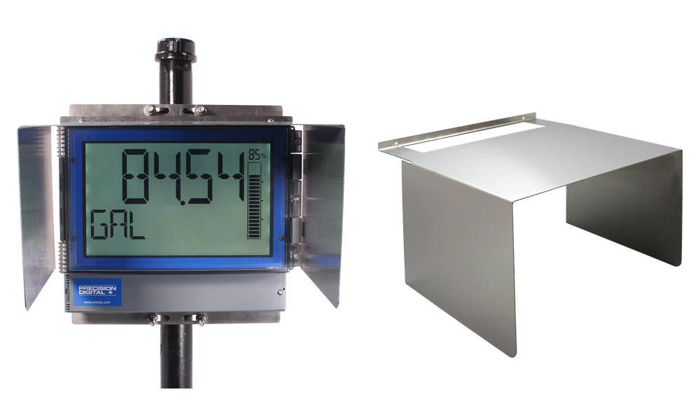
- Stainless Steel Sun Hood Accessory Available
- 3-Year Warranty
Why Use Loop-Powered Meters?
The most basic decision a user wishing to display a 4-20 mA signal on a digital display has to make is: should the meter be powered by line voltage or should it be powered by the 4-20 mA loop?
There are three main benefits of using loop-powered devices:
- No additional power required
- Easy wiring
- Additional digital displays can easily be added in the same loop
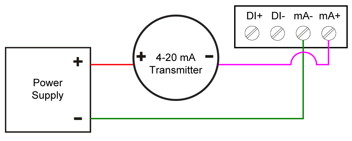
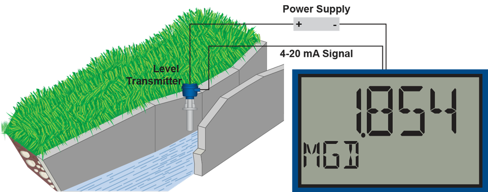
The following diagram illustrates how a loop-powered meter is wired. Notice there are only two connections made to the meter.
For more information on loop-powered meters, check out Fundamentals of Loop-Powered Devices and Loop-Powered vs Line-Powered Meters white papers.
Overview
Loop-Powered Flow Rate/Totalizers with Advanced Display and Control Features
The Loop Leader+ loop-powered large display flow rate/totalizers can be installed virtually anywhere to provide convenient and informative display of any 4-20 mA signal. One of the most convenient features of these instruments is their large, dual-line display which is typically used to display flow rate on the 2.8" 5-character alphanumeric top display and flow total, flow grand total, or a tag on the 1.5" 8-character alphanumeric bottom display. Both display lines use 14-segment, alphanumeric characters that provide much clearer indication of tags, units, or alarm messages than 7-segment characters do.
Further enhancing the display on these instruments is a 20-segment bargraph that also includes a numeric value of the percentage the bargraph represents. Free, PC-based, MeterView XL software that connects to the meter via a micro USB cable is available for programming and setup of the meters.
The PD4 is available in two configurations: Display only and with two solid-state relays and 4-20 mA analog output. All models come equipped with two open collector outputs and remote contacts. The open collector outputs are useful for alarm indication or pulse output. The remote contacts can be used to remotely operate the four programming buttons, to reset the total, to start/stop a timer/stopwatch, and more. The relays can be programmed for alarm indication, sample, timer, batch control, or stopwatch.
For intrinsically safe versions of these instruments please click here.
Front
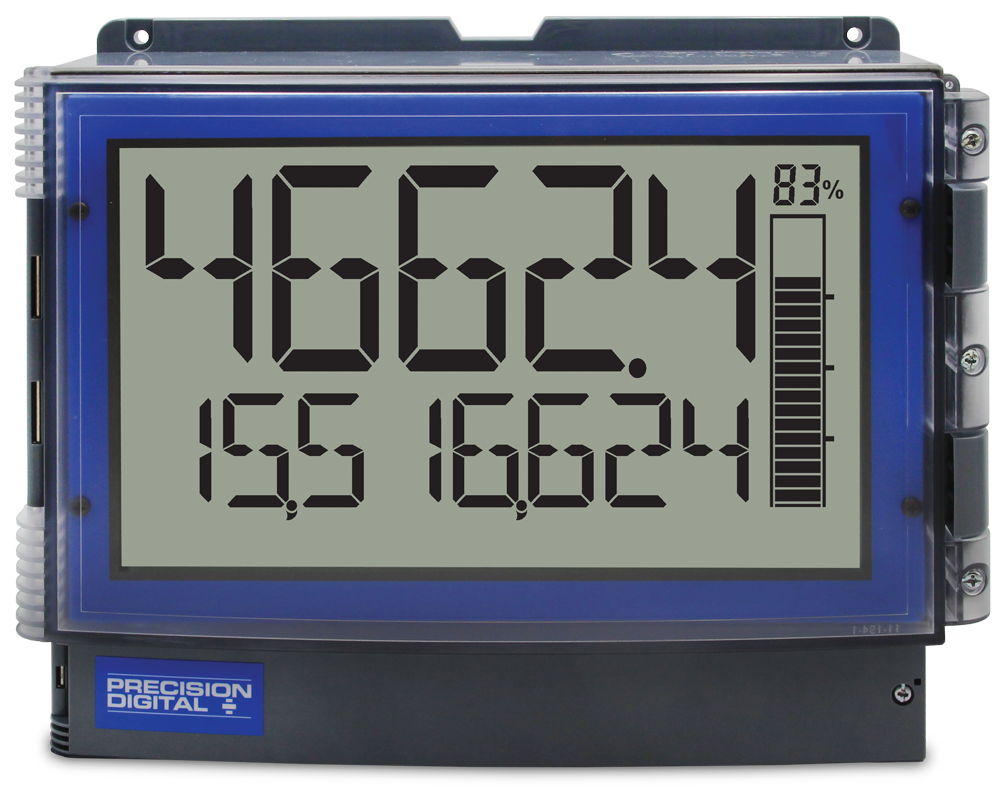
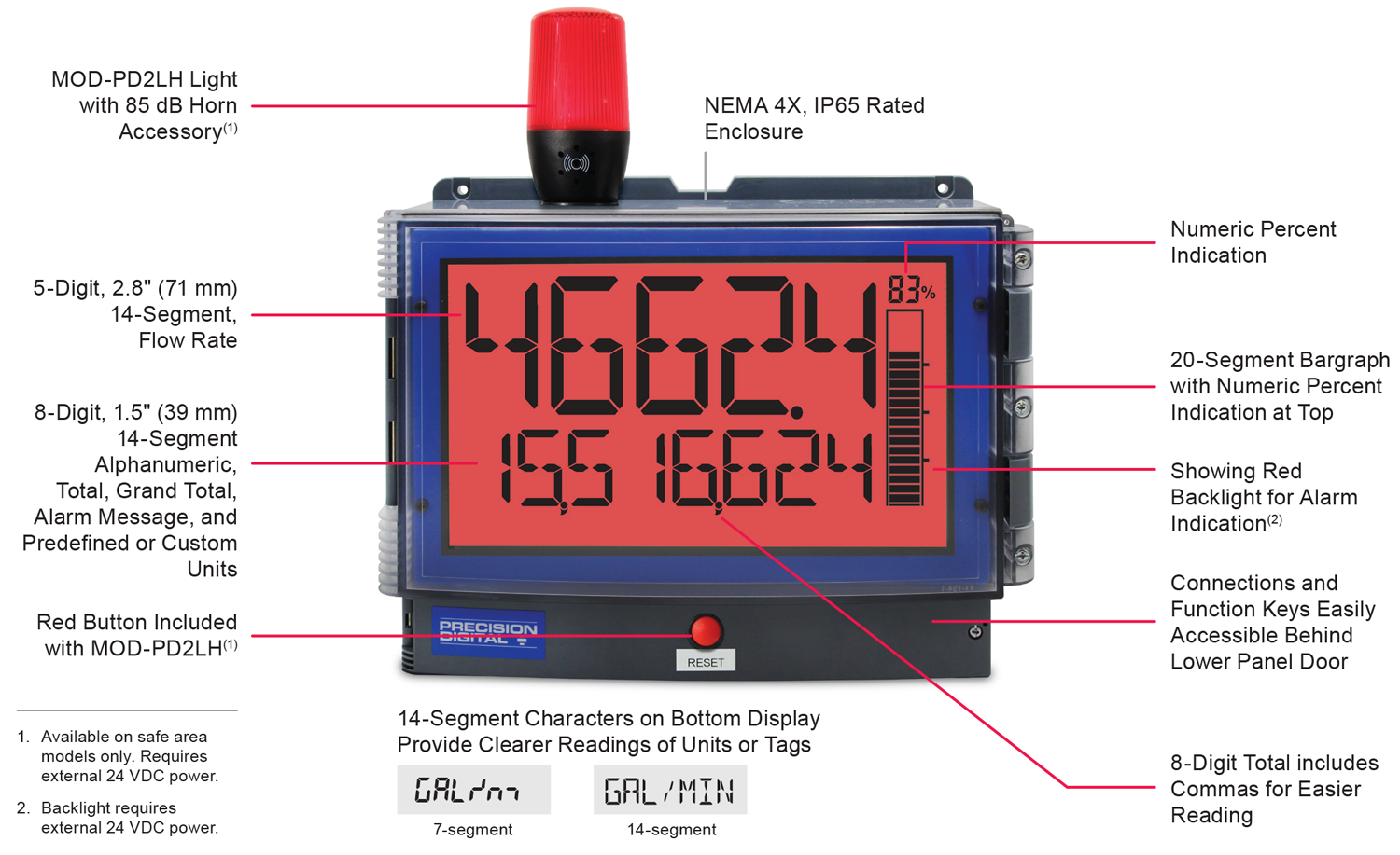
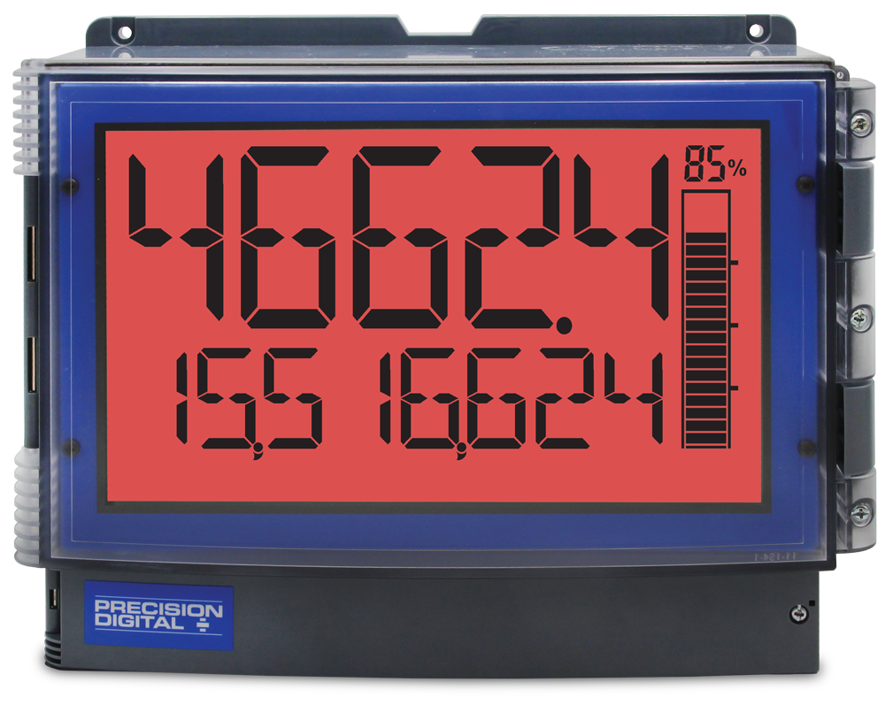
PD4-6624
- 5-Digit alphanumeric top line
- 8-Digit alphanumeric bottom line
- 20-Segment bargraph with numeric percentage
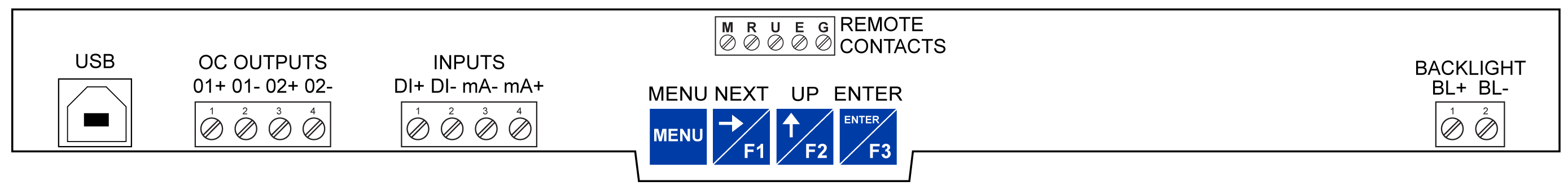
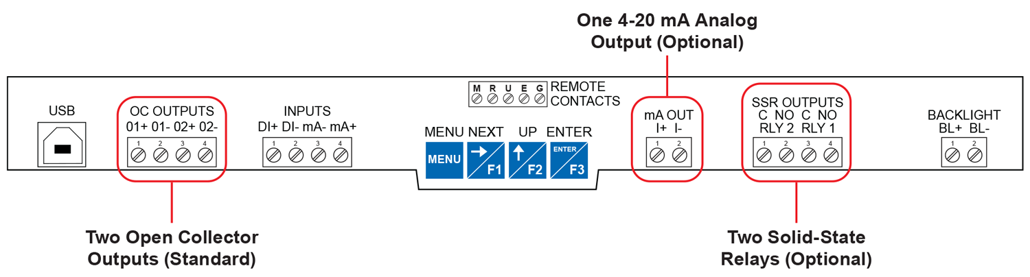
Connections
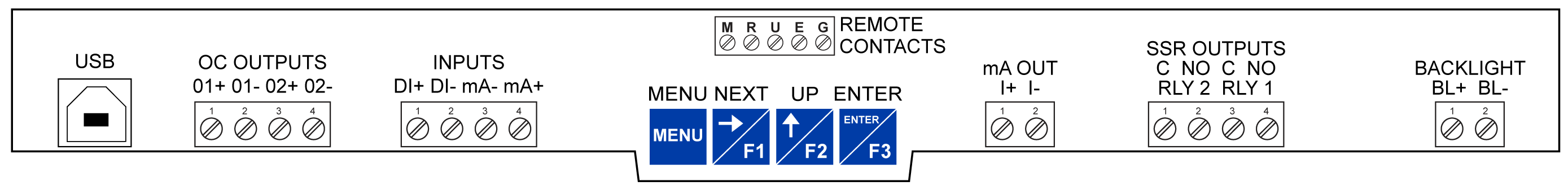
Connections for -L5N Option
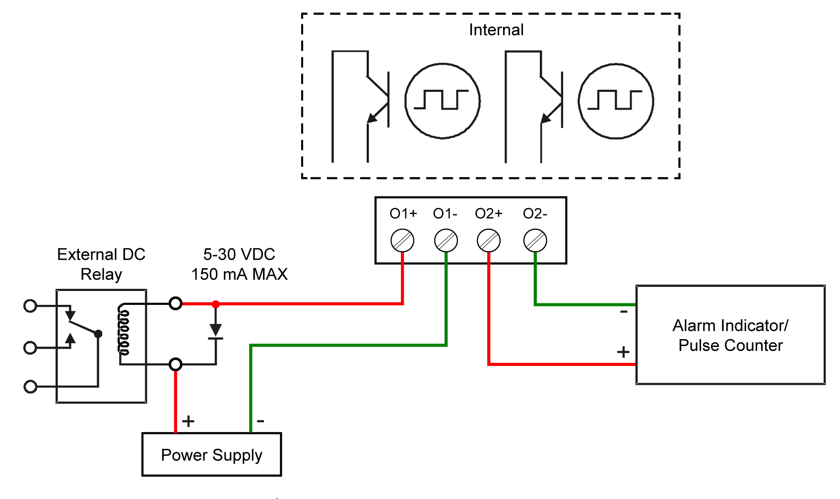
- (2) Open Collector Outputs Standard (150 mA max); Assignable to Pulse, Alarm, Timer, or Stopwatch
- Digital Input for Remote Operation of a Single Task
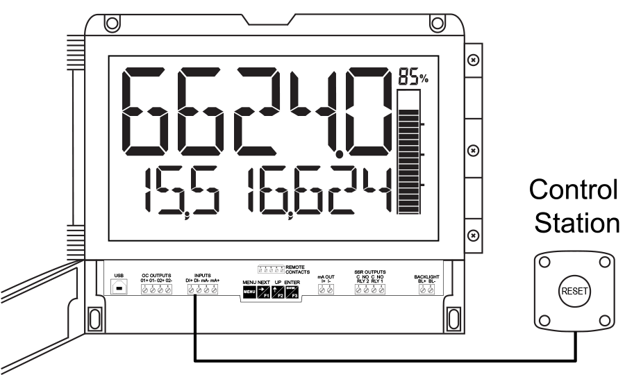
- Remote Contacts for Remote Operation of All Four Programming / Operation Buttons Using Control Station PDA2364-MRUE
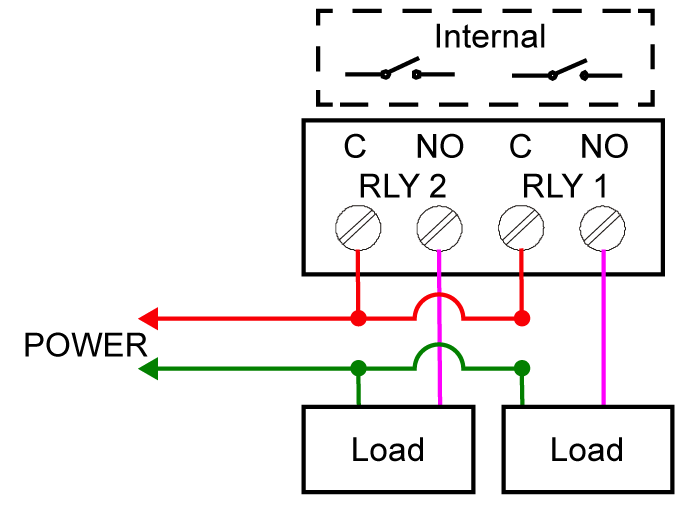
- (2) Optional Loop-Powered Solid-State Relays; Assignable to Alarm, Control, Timer, or Stopwatch
- Optional Isolated 4-20 mA Analog Output
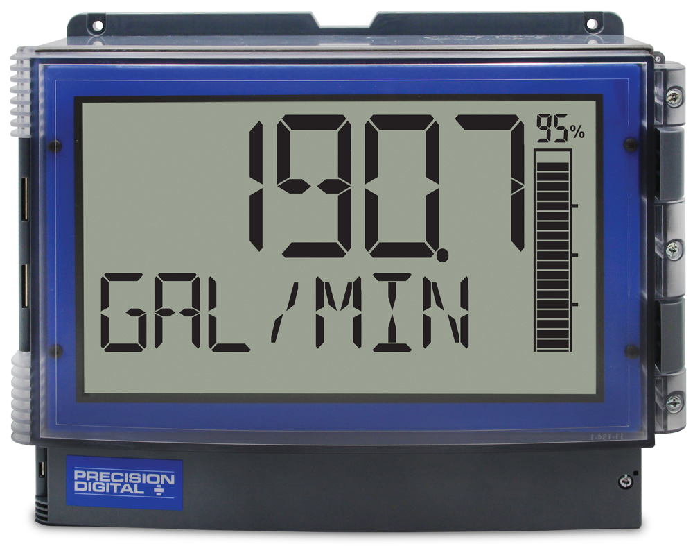
Display Features
PD4-6624 Flow Rate/Totalizer with Bargraph
For more information about the MOD-PD2LH light/horn & button modification series click here.
Display Flow Rate & Total at the Same Time
One of the key features of the Loop Leader+ rate/totalizers is their ability to display flow rate and total at the same time. In addition, the meter can toggle between the rate and total and their corresponding units as the following illustrates.

Wide Variety of Display Capabilities
In addition to the most common setup of flow rate on the top line and flow total on the bottom line, these meters can be set up for a variety of display configurations.
Display Flow Rate and Toggle Between Units & Tag
Display Flow Total and Toggle Between Units & Tag
Display Flow Total & Flow Grand Total and Toggle Between Units
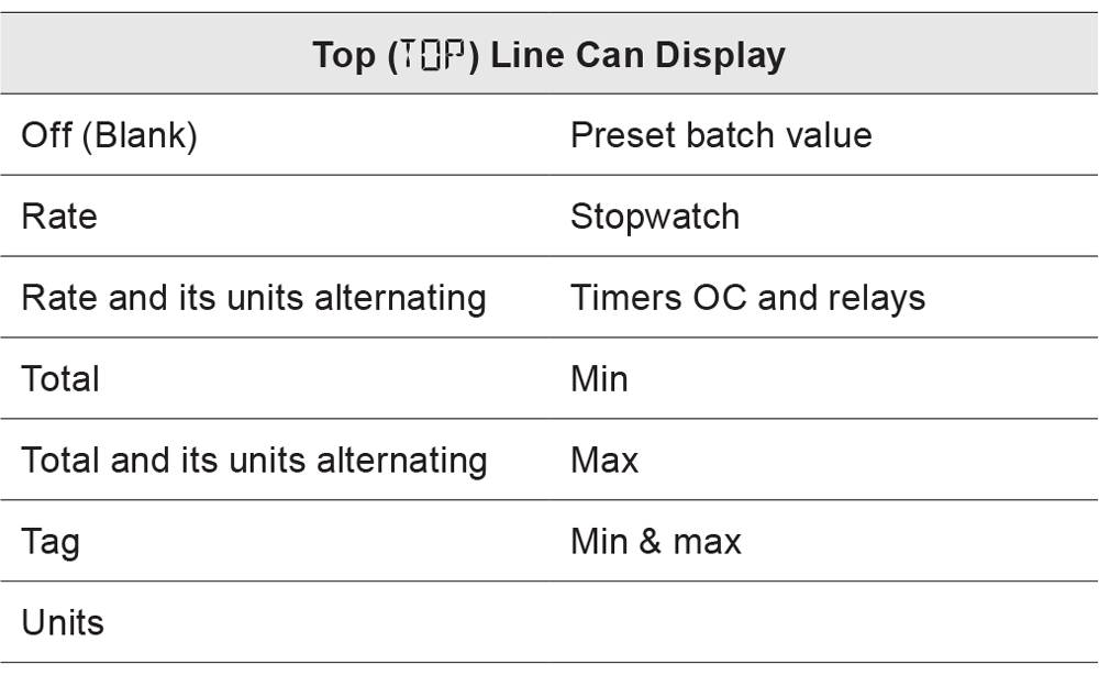
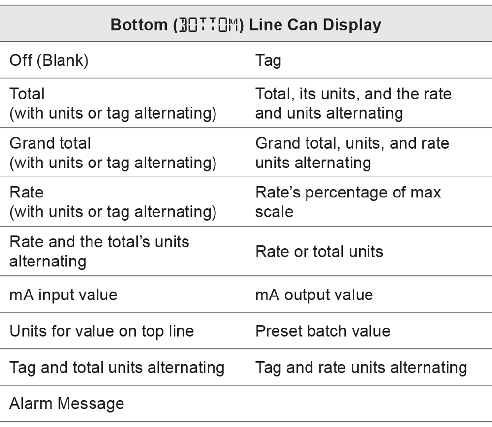
The following table shows the items that can be displayed on the Top and Bottom lines:
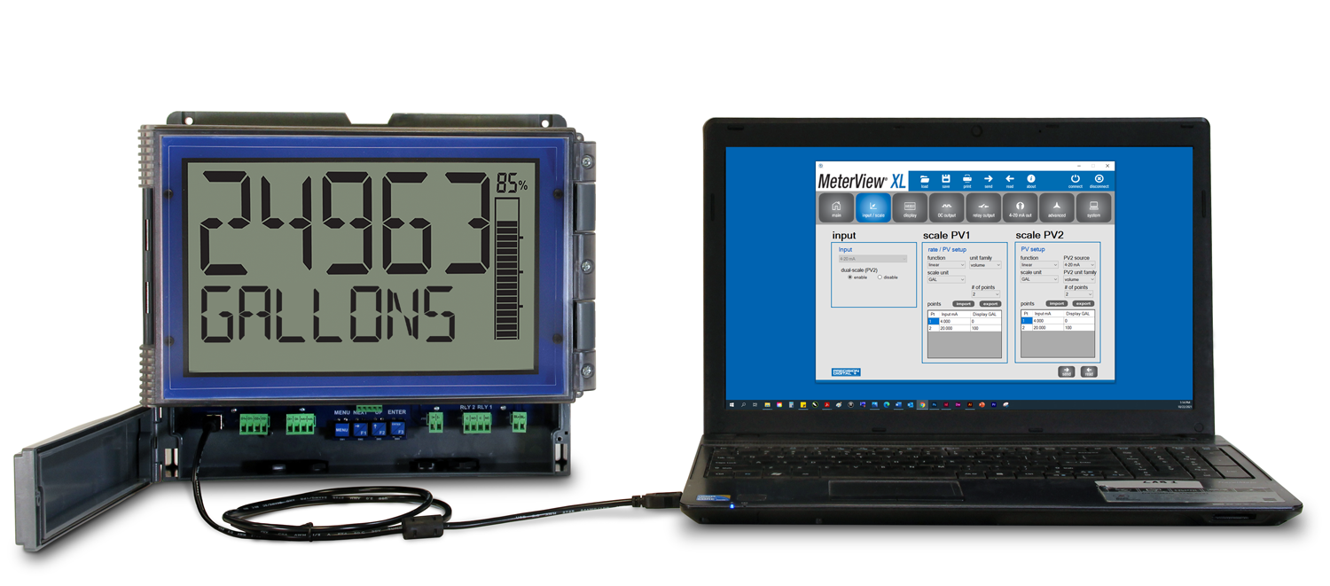
Dual-Scale Display Feature
Users can use the Loop Leader+ dual-scale feature when they want to show the same input in two different scales. For instance, the following example shows an application where the Loop Leader+ displays the input in gallons per minute and cubic feet per minute.

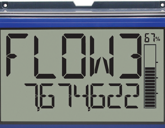
14-Segment Characters
Notice how much better letters like “T”, “N” and “K” appear as 14-segment characters on the bottom display vs. 7-segment characters found on other meters.
Large Informative Display
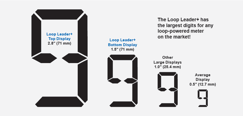
One of the most convenient features of the PD4 Loop Leader+ Series is its large, dual line display. With a whopping digit height of 2.8" (71 mm) on the top display, the Loop Leader+ has the largest digits for any loop-powered meter on the market! Even the 1.5" (39 mm) 8-character alphanumeric bottom display is bigger than most loop-powered large displays on the market. Plus, the 20-segment bargraph with percentage indication on top makes reading and understanding process values easier than ever. Predefined display units give users even more display flexibility, and the high contrast 24 VDC externally powered backlit LCD display is readable from far away and under various lighting conditions.
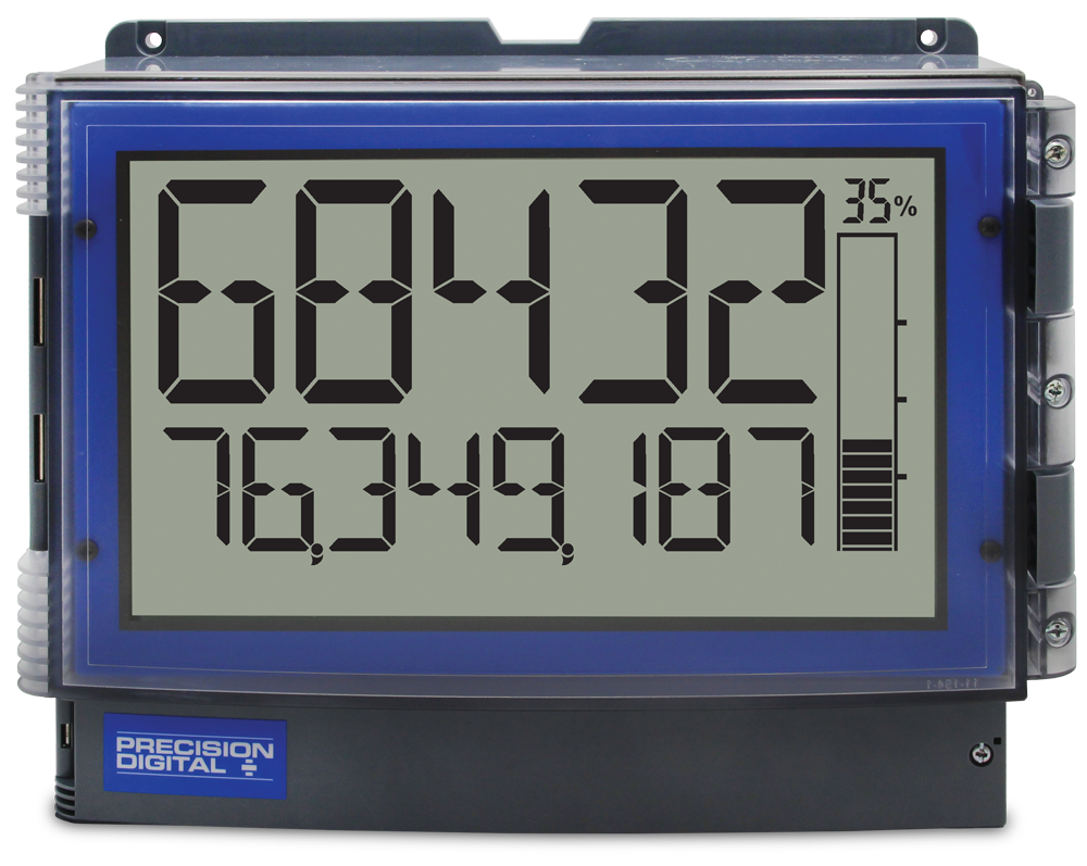
Commas Make it Easy to Read Big Numbers
The bottom display is set to show a comma separating the thousands and millions place by default if a numeric value is being displayed. This feature can be disabled or enabled using the Comma menu.
Red, Flashing Display When Alarms Occur
When an alarm occurs, the display can be programmed to turn red and flash. In addition, a unique custom alarm message for each of the two relays and two open collectors can be displayed on the bottom display. These features can be activated even if no relay or open collector is connected.
Backlight Turns Red on Alarm
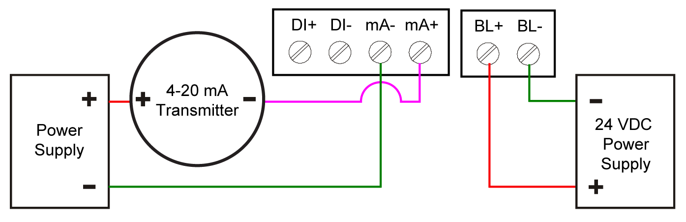
The externally DC powered backlight is standard on all Loop Leader+ meters. It provides optimimum visibility in any lighting condition and it can be programmed to turn red for alarm conditions. The backlight may be enabled or disabled using the Backlight menu. The backlight is enabled by default (input must be wired appropriately for the backlight to function). The backlight must be powered by an external power source.
Bargraph Provides Quick Understanding
The 20-segment bargraph helps users get a quick understanding of where their process is at. This bargraph also includes a numeric value of the percentage the bargraph represents. The bargraph can be programmed to represent either rate, a percentage of the rate, total, or it can be disabled.
Max/Min Display
The max & min readings (peak & valley) reached by the process can be displayed either continuously or momentarily.
- Display momentarily by pressing the F1 function key (default) or assigning to any of the other function keys or to the digital input in the User menu. Press Enter to lock/unlock max/min display.
- Display continuously by assigning either display line to max/min through the Display menu.
Any of the F1-F3 function keys (buttons) and the digital input can be programmed to reset the max & min readings.
Using 13 Digits to Display Total
The top and bottom displays can be setup to display a 13-digit total (9,999,999,999,999). The total will roll over to zero when it exceeds the limit.
Predefined and Custom Units
The meter has the most common predefined rate and volume units. If the desired unit is not available, the user can program a custom unit.
Total & Rate in Different Units
The user can select to display total in different units than the rate. For instance, a customer could measure flow rate in gallons per minute and total in acre-feet by simply selecting AF (acre-feet) units for the total. Additionally the user can enter a custom unit and conversion factor to display the total in any unit of measure.
Reduce Sun Glare On Your Process Meter Display!

New PDA24SH Sun Hood
The PDA24SH Stainless Steel Sun Hood improves the readability of the Loop Leader+ when mounted in direct sunlight by shading the instrument from the sun. The PDA24SH Sun Hood is made from 18 gauge 316 stainless steel and easily mounts to the enclosure of the meter.
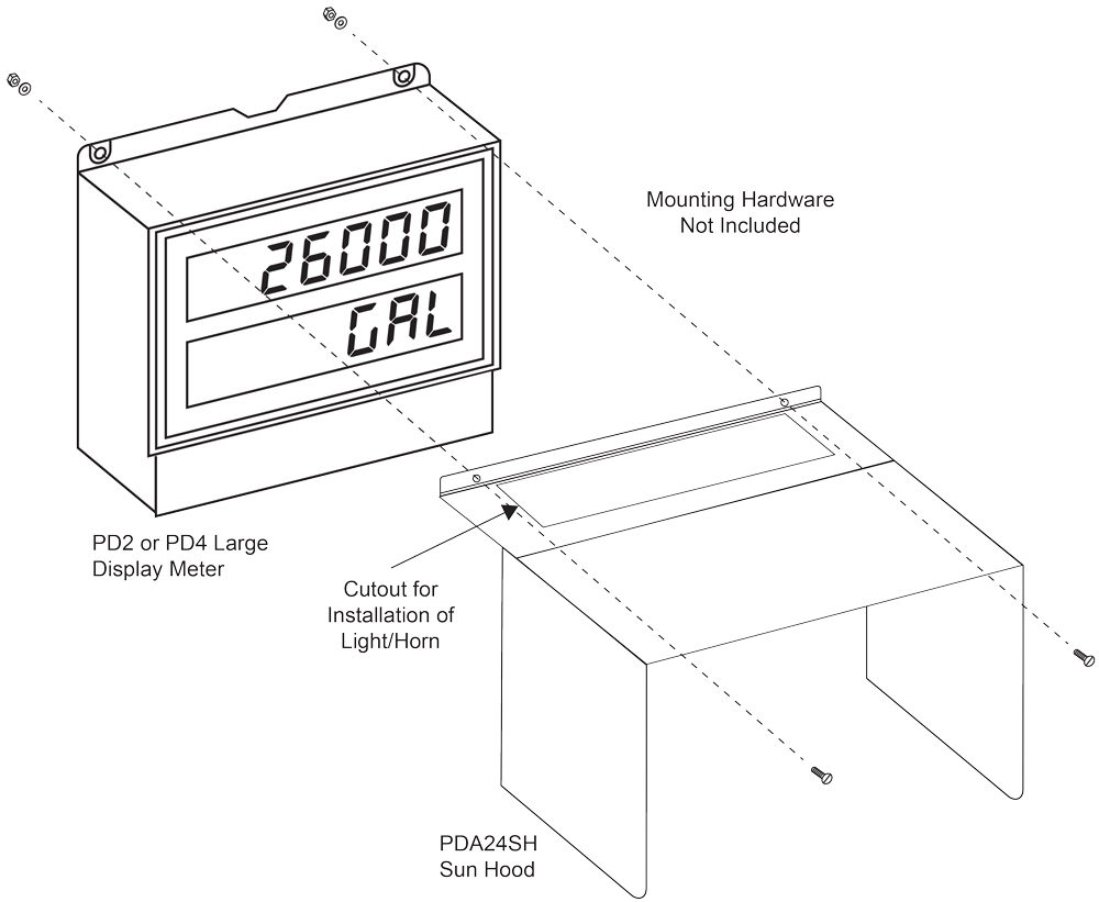
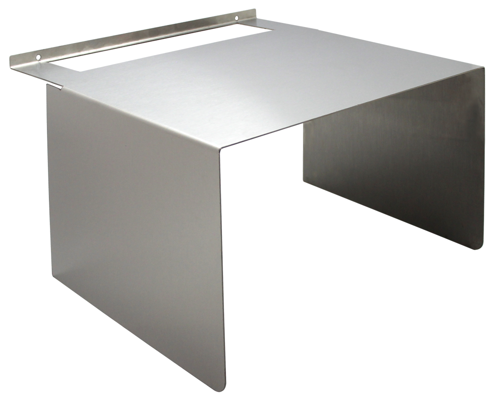
- Provides Shade for PD4 Loop Leader+ Series Large Display Meters
- Made from 18 Gauge 316 Stainless Steel
Outputs
Loop Leader+ meters come with two open collector outputs as standard and two solid-state relays and 4-20 mA output as options. The open collector outputs and relays generally operate in the same manner, with the major exception being the open collectors are not available for batch control and the relays are not available with pulse output features. The open collectors and relays can be controlled either automatically or manually. The alarm status (with a unique flashing red message for each of the two relays and open collectors) will show on the display even with no output wired.
Two Open Collector Outputs
The meter is equipped with two NPN open collector outputs that may be set up for pulse outputs, alarms, timed pulses, stopwatch on/off, or disabled. Pulse outputs can be set to transmit the rate, total or grand total. Output 2 may be used to generate a quadrature output based on the other open collector output. An output test mode is also selectable to generate pulses at a constant programmable frequency. The open collectors are commonly used to generate a pulse for every user-defined amount of flow that has been generated. For instance, the Loop Leader+ can be programmed to generate a pulse for every 100 gallons of flow.
Two Optional Solid-State Relays
The meter is optionally equipped with two solid-state relays that may be set up for alarms, sample, timer, batch control, or stopwatch. The relays are rated at 250 VAC/DC @ 1 A for resistive loads and 75 VA @ 0.6 A, 250 VAC/DC max (Safe Area only) for inductive loads. Alarms are available based on the PV value or the digital input.
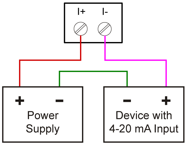
Optional Isolated 4-20 mA Output
The isolated analog output signal can be configured to represent the rate, total or to retransmit the 4-20 mA input signal without the need to scale the output. While the output is nominally 4-20 mA, the signal will accurately accommodate under- and over-ranges from 1 to 23 mA. The output can be reverse scaled such that the meter’s high calibration value outputs 4 mA and the meter’s low calibration outputs 20 mA.
Loop-Powered Relay Alarm Trip
The two solid-state relays can be used as a loop-powered relay alarm trip in both general purpose and hazardous areas. The Loop Leader+ two relays can be programmed for two different kinds of latching operation: Reset via momentary contact closure at any time or reset via momentary contact closure only after the alarm has cleared. And the meter’s display can be programmed to turn red and flash a unique custom alarm message for each relay – something not found on most loop-powered alarm trips.
Sampling Relay
A relay set to sample will trigger when the total or grand total value has incremented by a programmed amount. The relay can be programmed to stay on for a specified amount of time.
For example: if a relay is set to sample the total with a COUNT of 1,000 and a TIME of 10 seconds, the relay will energize for 10 seconds each time the total increments by 1,000 (e.g. 1000, 2000, 3000).
Resetting the Open Collectors and Relays
The open collectors and relays (alarms) may be programmed to reset in the following ways:
- Automatic (AUTO): Alarm will reset automatically once the alarm condition has cleared.
- Automatic/Manual (AUTO.MAN): Alarm will reset automatically once the alarm condition has cleared but can also be reset using the Enter button (or whichever function key is set to acknowledge) at any time.
- Latching (LATCH): Alarm must be reset manually and can be done so at any time. Press the Enter (ACK) button at any time to clear the alarm.
- Latching with Reset after Cleared (L-CLEAR): Alarm must be reset manually and can only be done so after the alarm condition has cleared. Press the Enter (ACK) button after the alarm condition has cleared to reset the alarm.
Timer Function
Timers are used in everyday life; one of the most common examples is the microwave oven. Industrial timers are used in process control applications where certain events or actions need to be controlled by time. Examples include automatic batch control applications, where the relay needs to be energized for a specific length of time.
The timer fuction is available on the open collector and relay outputs; which means that you can have up to four timers per meter. The start and stop actions can be triggered from the setup menu or by the function keys and digital input. The meter can be setup to display the off/on timer count down.
There are two modes of operation:
- Continuous Timer (Interval)
At the start of the timer the output is off and turns on after the Off Delay elapses. The output remains on for the duration of the On Time. The cycle repeats until the user stops the timer either from the menu or a function key. - One-Shot Timer
At the start of the timer the output is off and turns on after the Off Delay elapses. The output remains on for the duration of the On Time. The timer stops and the cycle does not repeat.

- A sensor detects the bottle is in place and triggers the digital input to start the timer
- The timer output controls the filling pump
- The On Time is set according to the time needed to fill the bottle
Batch Control
The Loop Leader+, when ordered with the two solid-state relays, can be used as a simple, one or two-stage batch controller. The user enters a preset and preclose value and sets the Loop Leader+ to either count up or count down. The top display will show the total and the bottom display will show the preset batch amount. The function keys are automatically changed so that F1 starts a batch, F2 opens the preset menu to allow the preset value to be changed, and F3 pauses/stops the currently running batch. Batching can be either automatic or manual.
Batch Control Operation Example
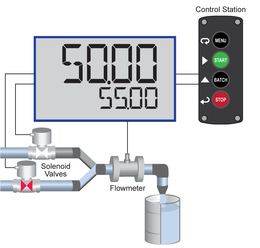
The following example shows how two-stage manual batch control functions with a Loop Leader+. This setup will establish a 55-gallon preset for the batch, with a main valve (high flow) that will close at 50 gallons, and a trickle valve (low or restricted flow) that will close at 55 gallons. Because the first batch overruns by 0.10, the batch preset will be changed to 54.90 for the next batch to compensate for overrun.
Manual Batch Control
The manual batch control feature is used for batch processes that the operator wants to start manually. It can also be used where the batch size needs to be manually adjusted for each batch. The batch can be controlled using a PDA2364-MSBS control station connected to the remote contacts.
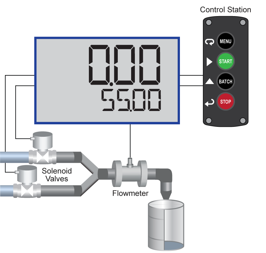
System Setup
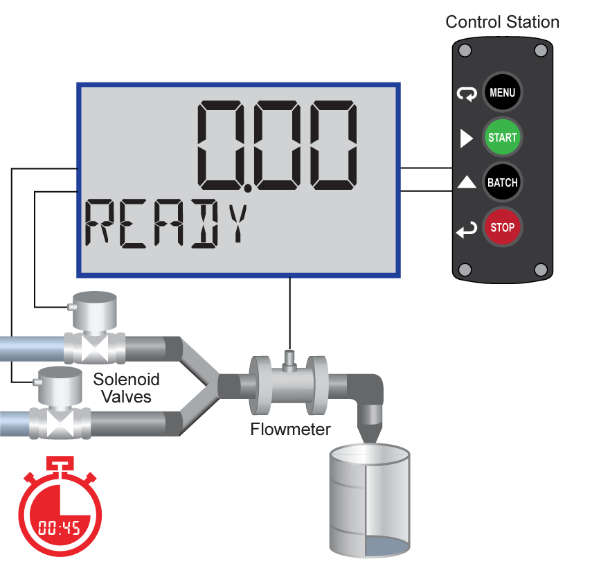
Both valves are closed with an empty barrel in place. The batched total is displayed in the upper display, the preset is selected for the lower display.
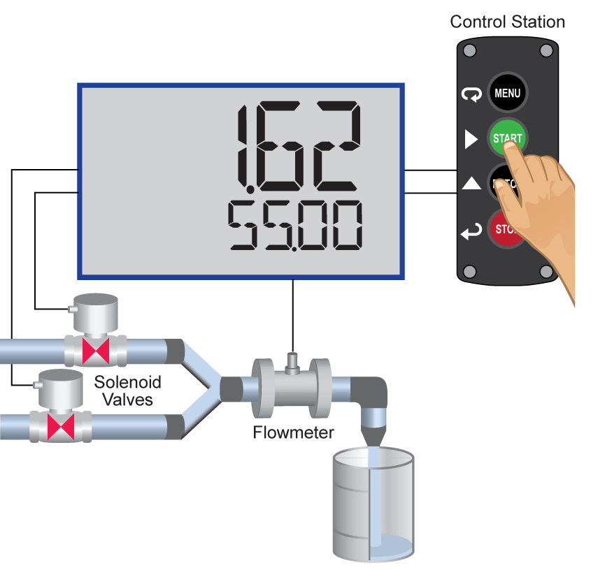
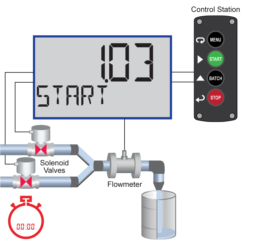
Batch Start
The START button or (F1) is pressed. Both valves open. The barrel begins to fill.
Preclose Valve
When the batch total reaches a value of 50.00 (Preset [55.00] – Pre-close [5.00]) the full-flow valve closes. The fill rate of the tank slows as a result.
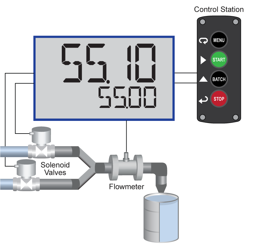
Completed Batch
When the batch is complete, the restricted flow valve closes. If overrun occurs, then the preset must be adjusted to compensate for the overrun amount. The next batch will only start after the START button or (F1) is pressed.
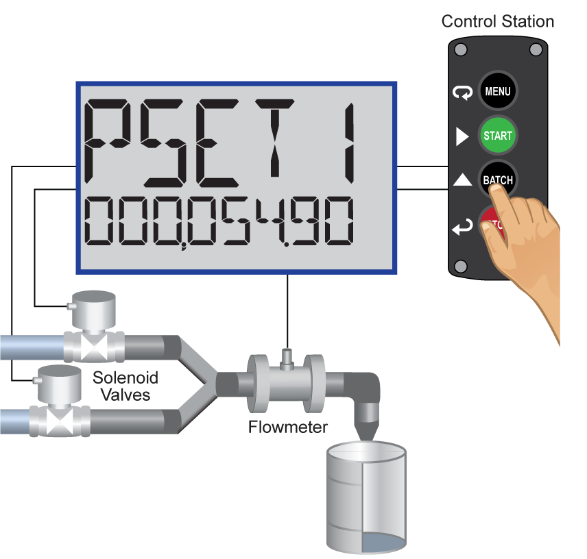
Overrun Correction
To compensate for overrun in the previous batch, adjust the preset to 54.90, so that the next batch is accurate (55.00).
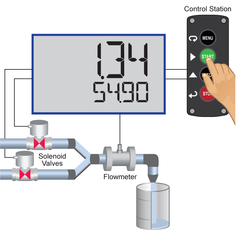
Manual Start of Next Batch
A new, empty, barrel is put in place and the START button or (F1) is pushed to manually start the next batch.
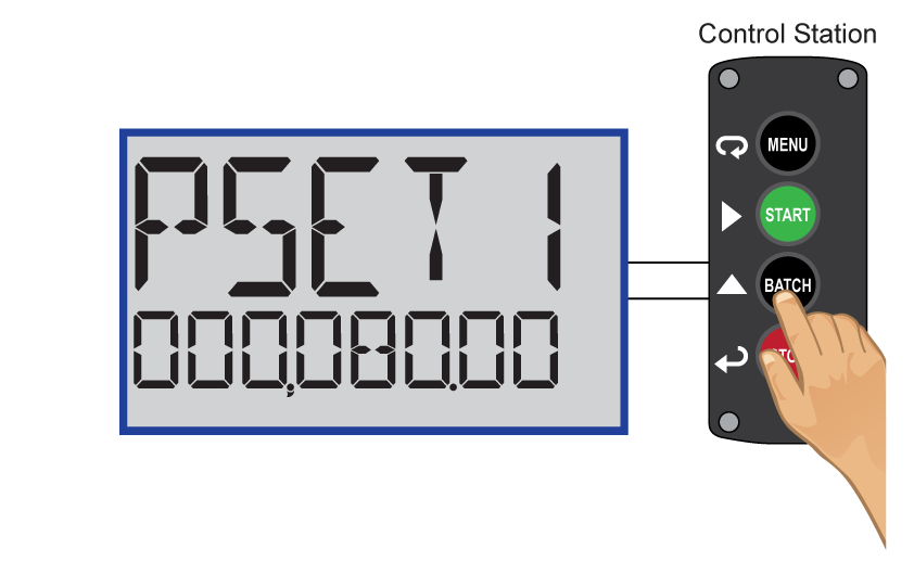
Change Batch Size
While the process is stopped, a new preset fill amount may be selected with the Batch key (F2) for a different size barrel.
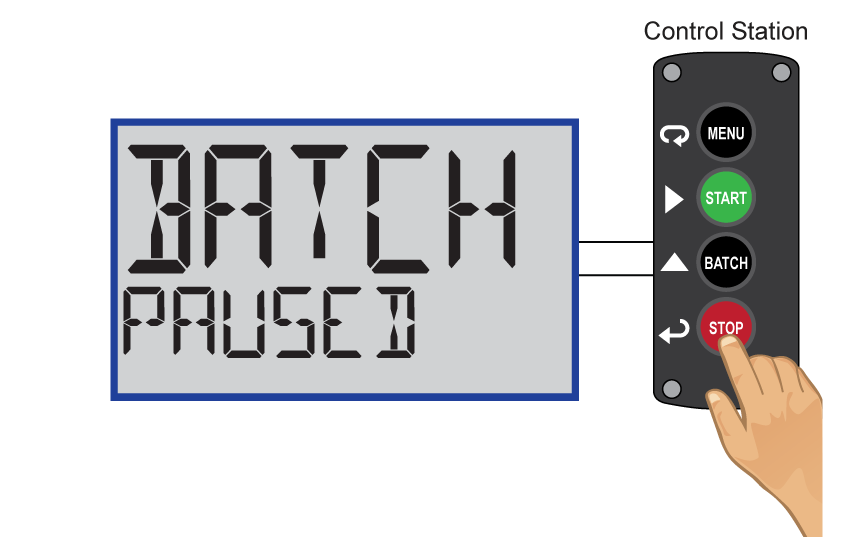
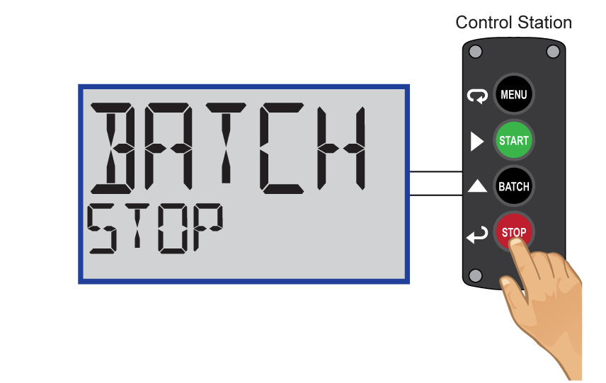
Pause/Stop
At any time, press the STOP button or Stop key (F3) once to pause the process, or twice to cancel the batch, which stops the process.

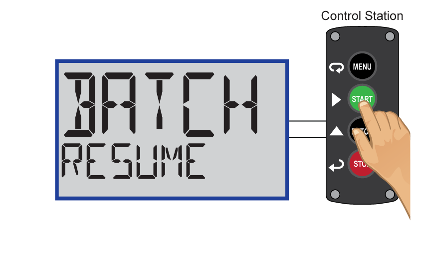
Resume Batch
If the batch has been paused, then press START button or (F1) to resume the batch process.
Automatic Batch Control
The automatic batch control feature is used for batches that start automatically once the previous batch is completed. There is no opportunity for the operator to change the batch size between batches. The batch can be controlled using a PDA2364-MSBS control station connected to the remote contacts.
System Setup
Both valves are closed with an empty barrel in place. The batched total is displayed in the upper display, the preset is selected for the lower display.
Batch Start
The START button or (F1) is pressed. Both valves open. The barrel begins to fill.
Preclose Valve
When the batch total reaches a value of 50.00 (Preset [55.00] – Pre-close [5.00]) the full-flow valve closes. The fill rate of the tank slows as a result.
Completed Batch
When the batch is complete, the restricted flow valve closes. If overrun occurs, then the preset must be adjusted to compensate for the overrun amount.
Start Delay
After the batch is completed, the operator removes the full barrel and places an empty barrel; the new batch starts automatically after 60 seconds (Time Delay).
Automatic Start of Next Batch
The next batch begins automatically after 60 seconds, both relays activate and both valves open.

Pause
At any time, press the STOP button or Stop key (F3) once to pause the process.
Resume Batch
If the batch has been paused, then press START button or (F1) to resume the batch process.
Stop Process
At the end of the shift, press STOP button or Stop key (F3) twice to stop the batch process.
Totalizer Capabilities
Loop Leader+ flow rate/totalizers can be programmed for a wide variety of totalizer applications. They can display total, grand total, or non-resettable grand total; the rate can be displayed with a time base of seconds, minutes, hours or days. The user can program a totalizer conversion factor, a non-resettable grand total, password protection, and several total reset methods.
8-Digit Total & Grand Total Display, Up to 13 Digits Using Both Lines
The Loop Leader+ flow rate/totalizer can be programmed to show eight full digits of total on the bottom display or 13 digits of total using both the top and bottom displays. In both cases, the display can be programmed to include commas to make it easier to read the very large numbers; ie 44,987,356.
In 13-digit mode, the bottom line shows the least significant digits and the top line shows the most significant digits. The meter is not capable of displaying commas on the top line, so this number is actually 1,211,230,379. The commas can be removed from bottom if desired. See sample on bottom, right.
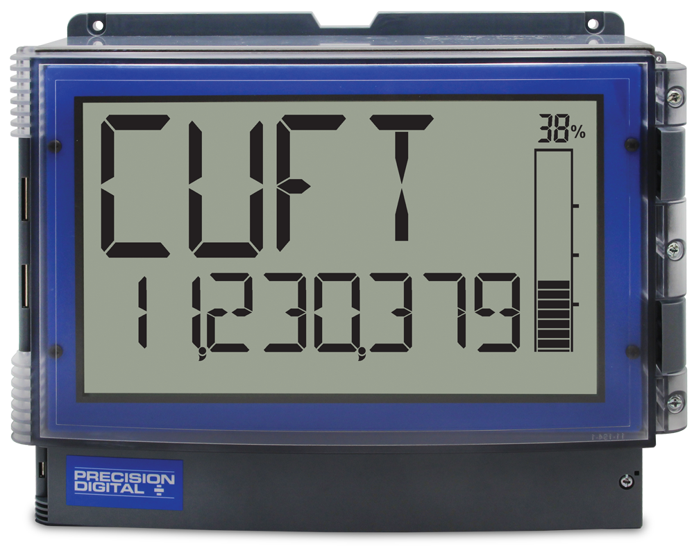 8 Digits of Total on Bottom
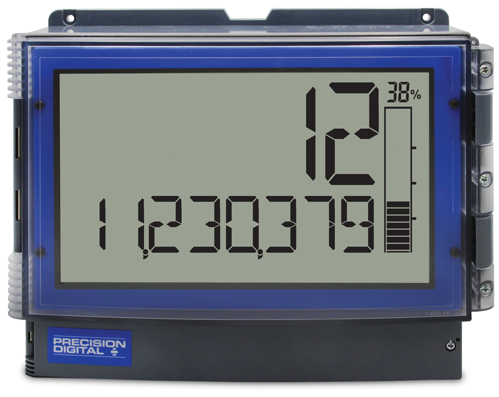 In 13-Digit Mode
Totalizer Conversion Factor & Multiplier
The user can enter a totalizer conversion factor that allows the meter to display total in different units than the rate. For instance, a customer could measure flow rate in gallons per minute and total in millions of gallons. A multiplier may be selected to automatically display the value in kGAL, MGAL, etc. Use the custom units to display the total in any unit of measure including units in languages other than English.
Totalizer Password Protection
The total and grand total can be password protected so they can be reset only by authorized personnel
Non-Resettable Grand Total
The user can set up the grand total to be non-resettable by selecting YES for PERMLOCK in the Advanced - Grand Total - Reset menu. Once this is done, the grand total can never be reset.
Low-Flow Cutoff
The user may program the meter for a low-flow cutoff such that the meter displays zero below this point, regardless of the input value.
Remote Total Reset
The total can be reset via an external contact closure on the digital input.
Front Panel Total Reset
The three front panel function keys can be programmed to reset the total and grand total. This makes it possible for the user to reset either the total or the grand total by pressing the appropriate function key. Of course, if the total or grand total is password protected, they will not reset when the function key is pressed unless the password is entered.
F2 Function Key is Programmed
for Reset by Default
Total Alarms
The Loop Leader+ two open collectors and the two relays can be set up to alarm when the total reaches a user-defined set point. A variety of reset modes are available and the user can also program time delays and fail-safe operation.
Total Stored in Non-Volatile Memory
Total and grand total values, and all programmed settings are stored in non-volatile memory for a minimum of ten years if power is lost.
Input Signal Conditioning
To satisfy applications that require scaling in ways other than the usual 2-point linear method, the Loop Leader+ can also be scaled for square root (differential pressure flow), programmable exponent (open channel flow) or round horizontal tank volume calculation.
For existing processes that require these linearization capabilities, one of the great benefits of loop-powered meters is that they get their power directly from the 4-20 mA loop and thus require no additional wiring. All a user has to do is break the existing loop and wire in the meter. For this reason, loop-powered meters are very easy to add to existing applications such differential pressure flow, open channel flow, or round horizontal tank volume calculation.
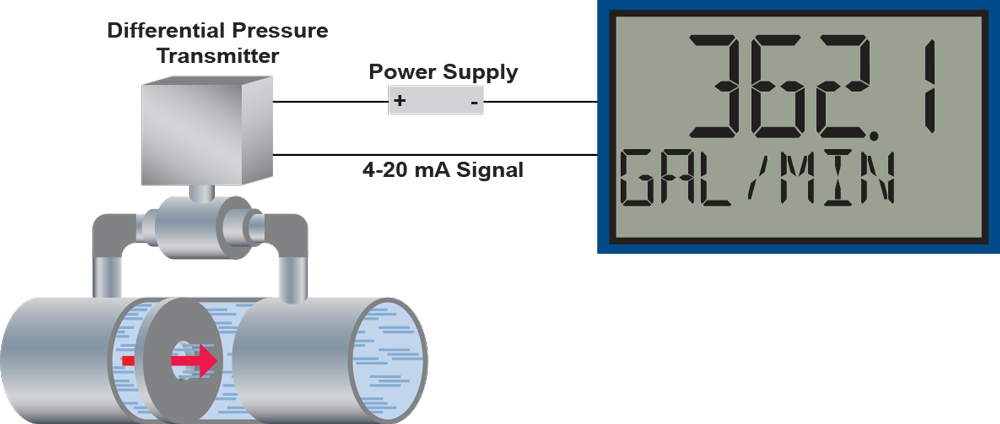
Differential Pressure Flow
The Loop Leader+ can display flow rate and total by extracting the square root from the 4-20 mA signal from a differential pressure transmitter. The user selectable low-flow cutoff feature gives a reading of zero when the flow rate drops below a user selectable value.
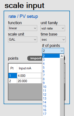
Multi-Point Linearization
Meters are set up at the factory for linear function with 2-point linearization. Up to 32 linearization points can be selected for rate under the linear function. Multi-point linearization can be used to linearize the input for non-linear signals to convert level to flow using weirs and flumes with complex equations.
Open Channel Flow
The Loop Leader+, in combination with an ultrasonic level transmitter, makes for an economical way to measure and display open channel flow rate in most weirs and flumes. A guide such as the ISCO Open Channel Flow Measurement Handbook can provide the user with all the information needed: the exponent used in the flow equation for the desired flow units and the flow rate for any given head height. For example, to display the open channel flow rate from a 3" Parshall flume, the ISCO handbook advises the exponent is 1.547 and at the maximum head height of 3.0 feet, the flow rate is 3.508 MGD.
| Function | Desire | Programming |
| Open Channel Flow | 3" Parshall flume | Set Programmable Exponent to 1.547 |
| Flow Ratew | Millions of Gallons per Day (MGD) | Set 4 mA = 0 & 20 mA = 3.508 Time base = Day |
| Total | Millions of Gallons | Set Totalizer Conversion Factor = 1 (password protect total reset) |
| Non-Resettable grand total | Program meter so grand total can never be reset | Set non-resettable grand total |
| Display | Display Flow Rate and Total at the same time | Set upper display for Grand Total and lower display to toggle between rate and total. |
| Sampling | Take a 1 pint sample every 100,000 gallons | Set up relay for sampling and to trip every 0.1 million gallons. Set up sampling time such that 1 pint is sampled. |
Physical Features
The Loop Leader+ is designed for ease-of-use in industrial applications where it will be exposed to wet, dusty, hot, cold and other adverse conditions. The Loop Leader+ is housed in a rugged NEMA 4X / IP65 enclosure, can operate over a wide temperature range, includes removable screw terminal connectors, and it carries electrical safety approvals. All of these features are backed by a 3-year warranty.
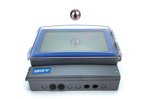
Type 4X / NEMA 4X Front Cover
Not only does the Loop Leader+ Type 4X approval indicate it is waterproof, it also indicates it is rugged. Part of the Type 4X test is to drop a 2 inch, 1 lb, solid stainless steel ball from 4 feet on top of the meter’s cover.
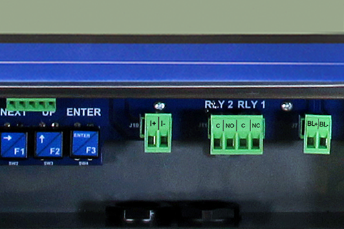
Removable Screw Terminal Connectors
Industrial applications require screw terminal connections for easy field wiring and the Loop Leader+ goes one step further in convenience by making them removable also.
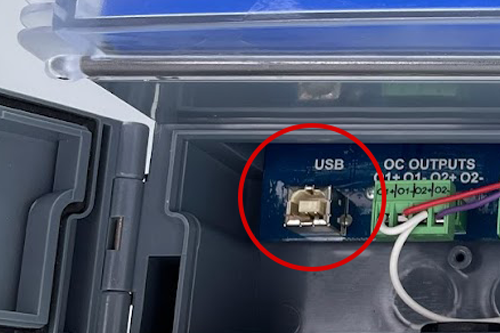
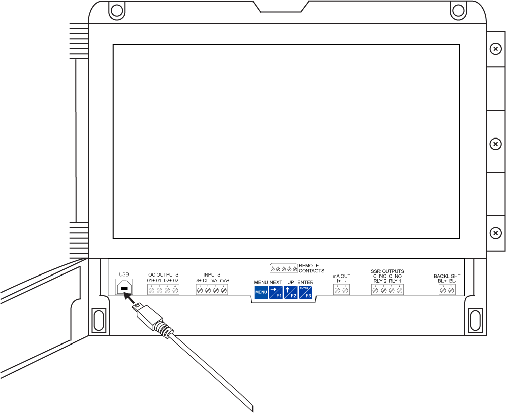
USB Port
A USB port located inside the lower panel door of the meter allows it to be connected to a PC for use with free MeterView XL software. The meter is powered by the USB connection during programming, if a 4-20 mA loop is not connected.

Wide Operating Temperature Range
The Loop Leader+ can operate from -40 to 75°C (-40 to 167°F) in safe areas and from -40 to 70°C (-40 to 158°F) in hazardous areas. This means it can be installed in a wide variety of indoor and outdoor industrial applications. And over this range, the Loop Leader+ will drift no more than 0.003% of calibrated span/°C from -40 to 75°C ambient.
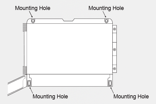
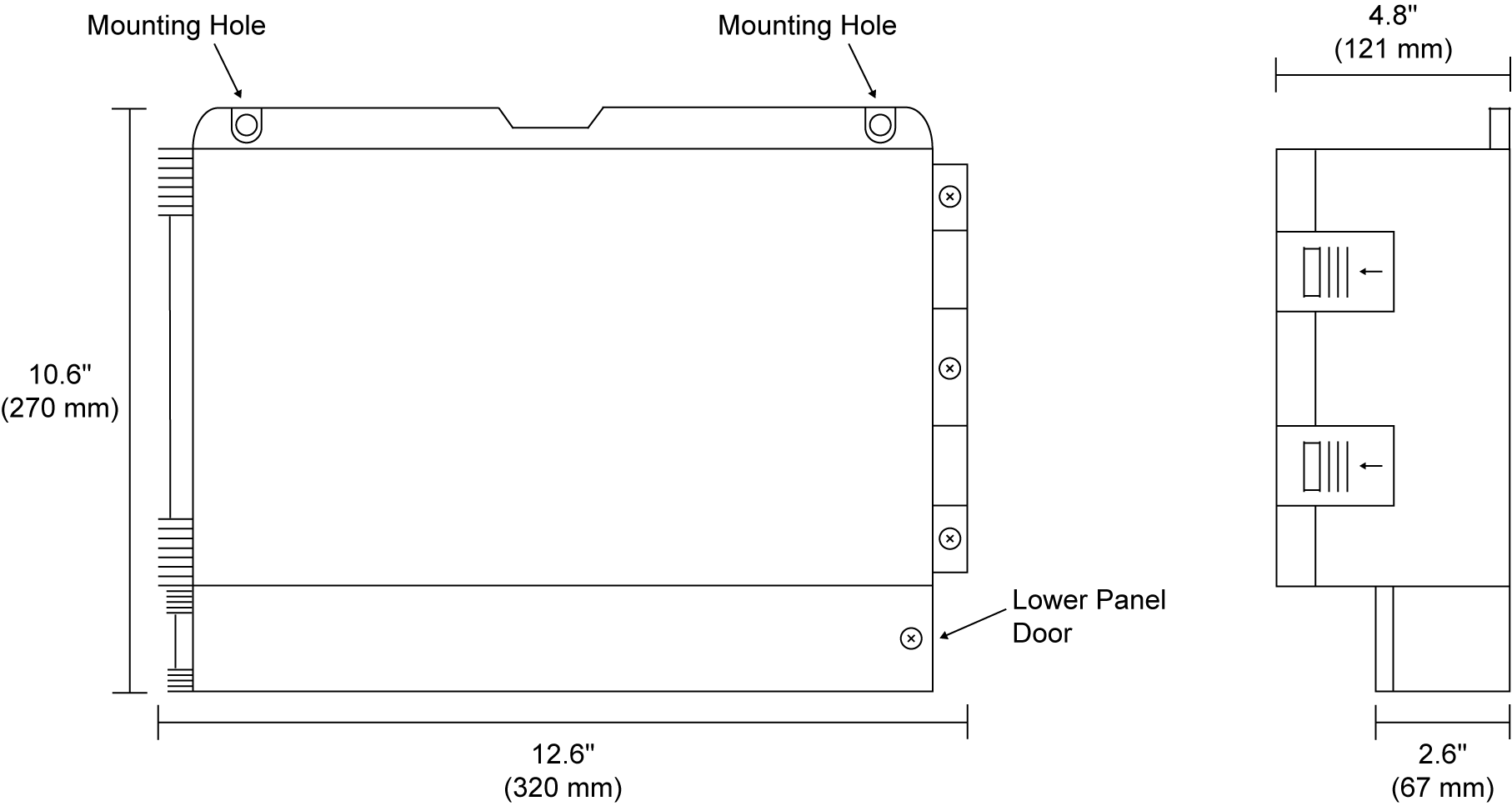
Integral Holes for Wall Mounting
The Loop Leader+ back panel includes four holes for convenient wall mounting.
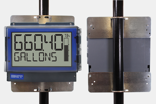
Pipe Mounting Kit
The PD4 can also be mounted to a pipe using the optional pipe mounting kit (PDA6260). This kit includes two mounting plates, two U-bolts, and the necessary nuts and bolts.
Operational Features
Once the meter has been installed and the lower panel door secured, the user can still operate the meter by connecting a control station to the Remote Contacts on the connector board. The user can then operate the four buttons as they are set up by default or change them to provide a variety of different functions by using the programmable function keys.
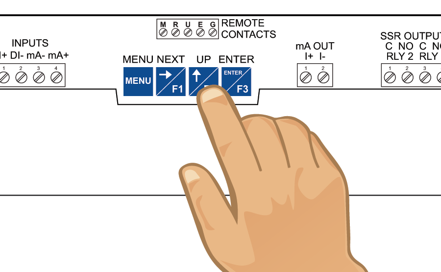
Programmable Function Keys
Three buttons labeled F1, F2, and F3 located inside the lower panel door can be programmed as function keys to perform a variety of meter functions simply by pressing the button. These include resetting the total, operating the batch control functions, resetting the meter’s relays or open collectors, starting and stopping timers, and displaying max/min values. The default settings for the function keys are:
| Button | Description (Default Settings) |
 | Press to display grand total. Continue pressing to cycle through max, min, rate, and total displays. |
 | Press to access the Reset menu. Press F1 to scroll through the options. Press F3 to reset the currently displayed parameter. |
 | Press to acknowledge all manually resettable relays or open collectors. Press to lock/unlock the display value after pressing the F1 key. |
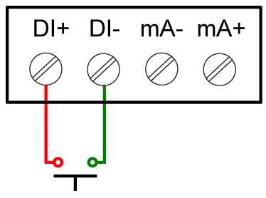
On-Board Digital Input
A digital input is standard on the meter. This digital input is programmed identically to the function keys. The input is triggered with a contact closure between DI+ and DI-, or with an active low signal. For a complete list of Digital Input settings, see the instruction manual.
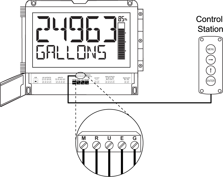
Remote Operation of Meter
The meter can be operated remotely by connecting a PDA2364-MRUE control station to the Remote Contacts located behind the lower panel door of the meter or use PDA2364-MSBS control station for batch control operation.
For more information about control stations, please see PDA2360 Plastic Control Stations.