Features
- Light/Horn and Button Mounted and Wired to Meter
- Single Lights in Red, Green, Yellow, Blue, or White Available
- Units with One of Five User Selectable Lights Available
- Three Color Light Stack with Red, Yellow, and Green Lights Available
- Light/Horn Powered from Meter or External Power Supply
- Light and Horn Can be Controlled Independently Using Separate Relays
- Light/Horn Programmable for Variety of Reset Functions, Including:
- Silence Horn at Any Time
- Light Stays on Until Alarm Clears
- Light Can Be Wired to Flash or Stay Steady On
- IP65 Rated
- 85 dB Horn
- Operates from -5 to 40°C (23 to 104°F)
- Control Station Accessory For Remote Operation of Light/Horn Button
What's Included
Light/Horn
Button and 9 Labels
Hole Drilling on Enclosure
Installation and Wiring
Meter
⚠ Meter sold separately.
Overview
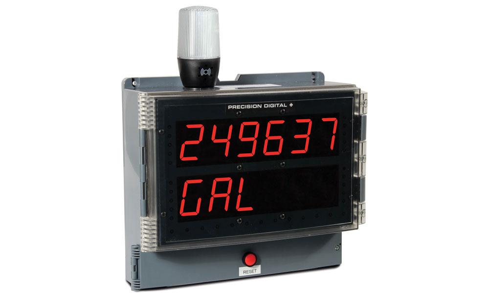
Transform a Precision Digital meters and controllers housed in an enclosure into an efficient display, control, and alarm system with the MOD-LH series. It provides a light/horn to boost visibility of alarm conditions, a button that connects to the meter's digital input to control or reset the alarms, and hole drilling on the enclosure for both the light/horn and button to make user installation and wiring quick and easy. Enclosure and meter are sold separately.
The MOD-LH series is compatible with a wide range of Precision Digital NEMA 4 and NEMA 4X enclosures as well as meters and controllers including the ProVu, Trident, Loop Leader, and ConsoliDator+ Series. Overall, the MOD-LH series is a simple solution for Precision Digital meters and controllers that adds audible and visual ways to indicate critical alarms.
Installation of the light/horn accessory voids all of the PD2 and PD4 agency approvals. The NEMA 4X and IP65 ratings are not affected.
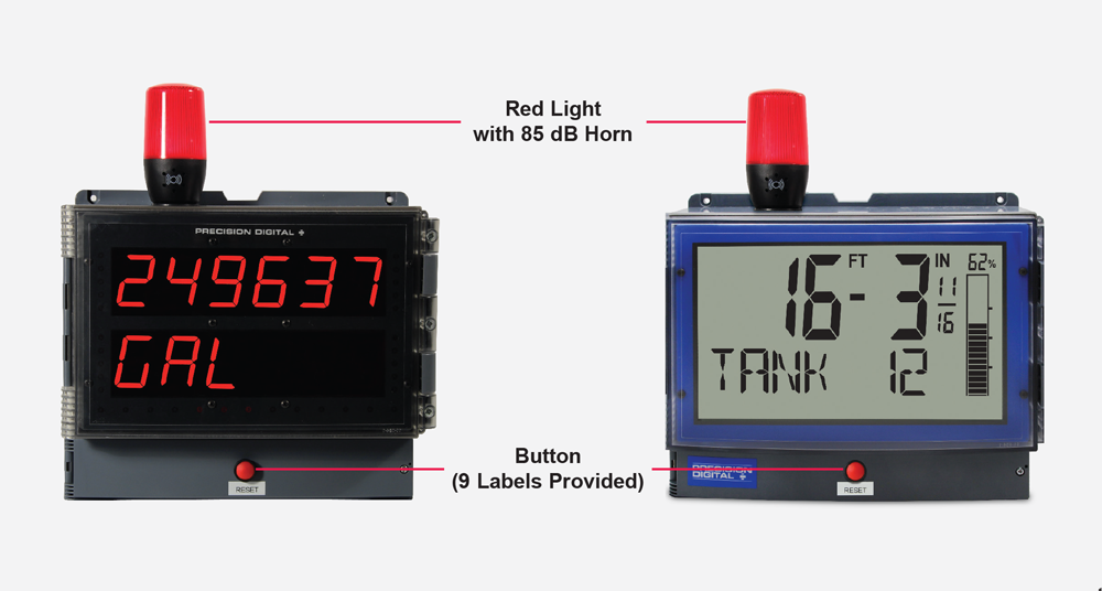
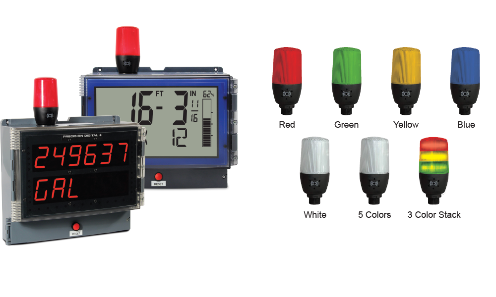
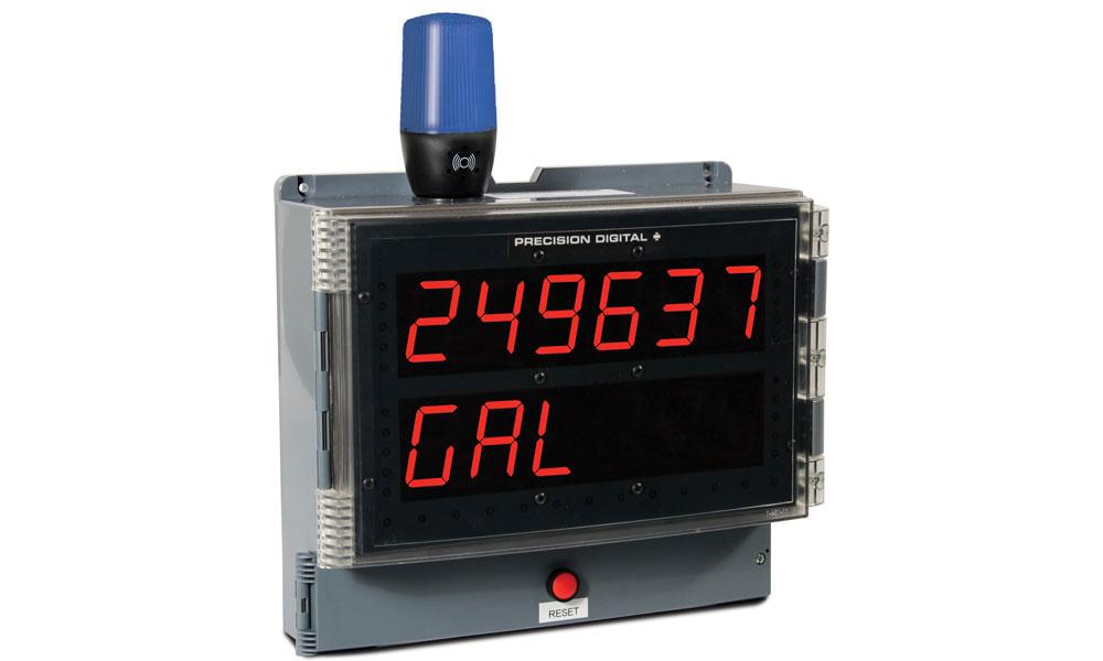
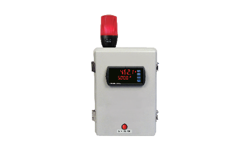
PD2 and PD4 Meters Shown with MOD-PD2LHRB1 Red Light/Horn and Button. Meters Sold Separately.
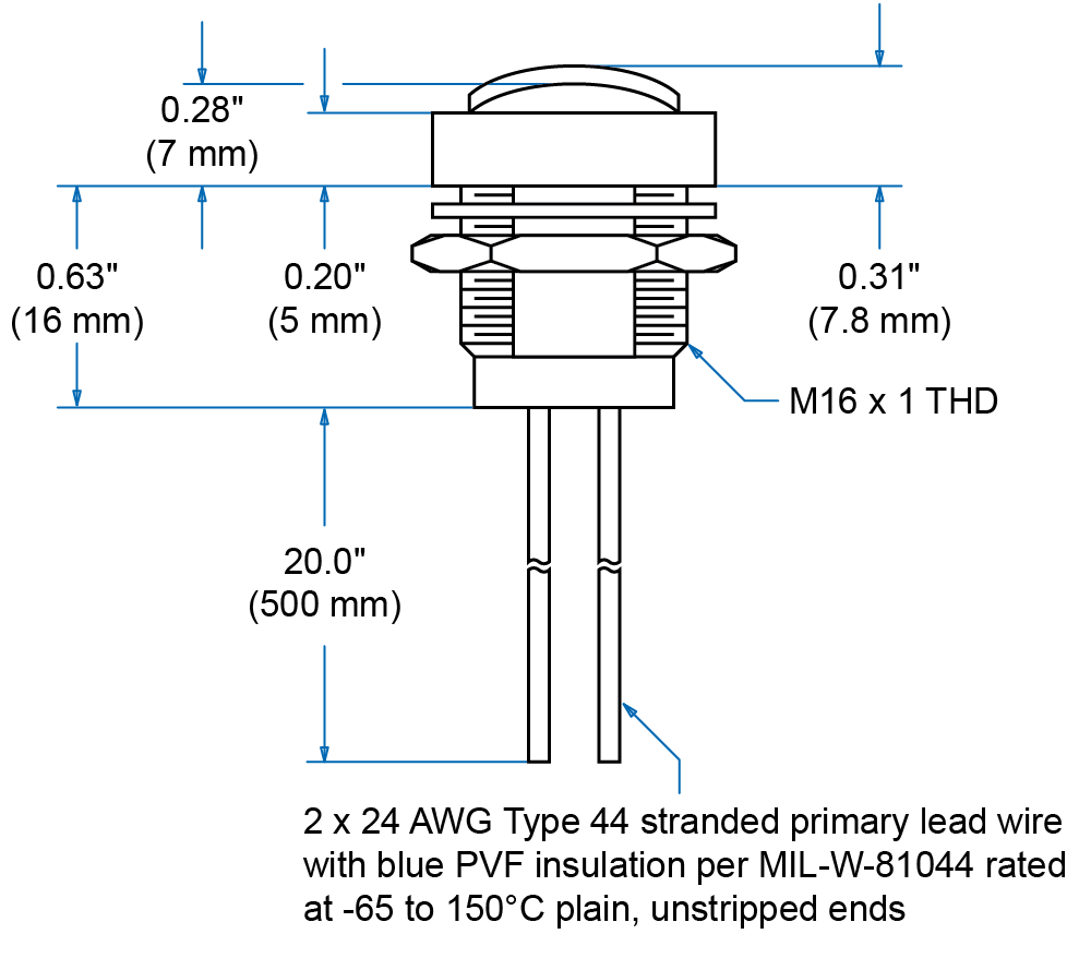
Light/Horn
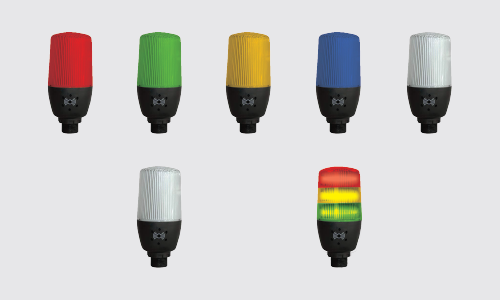
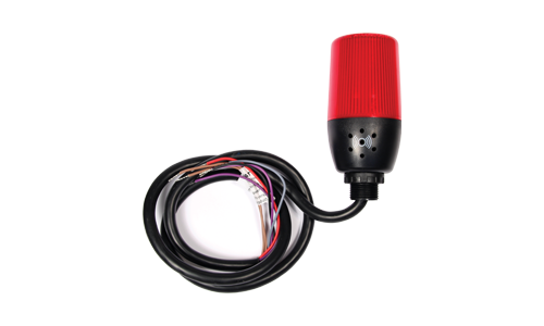
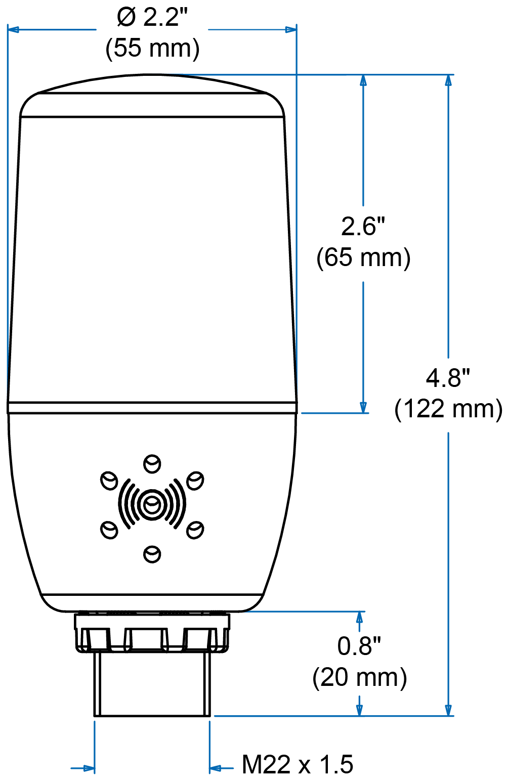
The light/horn is available in three different light configurations and each comes with a built-in 85 dB horn.
The first light option is a single color light in either red, green, yellow, blue, or white. The second light option is a user selectable light with five color options in either red, green, yellow, blue or white. Simply connect the appropriate wire to display the desired light color. The third option is a light stack with red, yellow, and green lights that can turn on independently (not compatible with PD4).
The light can be wired to flash (not available on MOD-PD2LH5CB1) or stay steady on. Both the light and horn can be controlled independently of each other using separate relays on the meter, and may be reset in a variety of ways based on the connected meter's relay reset capabilities.
Button
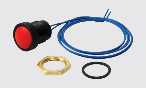
The button connects to the meter's digital input and it can be used to remotely control the light/horn such as resetting, acknowledging, or silencing an alarm. Nine (9) printed labels are provided to identify the button's action including: RESET, BATCH, ACK, TARE, SILENCE, STOP, START, PAUSE, and START/STOP.
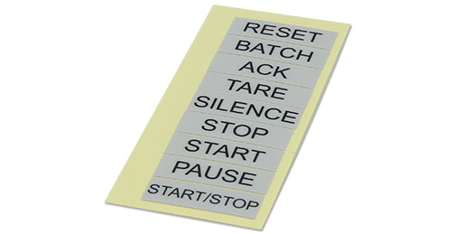 (9) Printed Labels Provided
Control Capabilities
The light and horn can be controlled independently of each other using separate relays on the Precision Digital meter they are connected to. These relays can be programmed for automatic or manual reset action to satisfy a wide variety of audible and visual alarm applications.
Power Options
Precision Digital meters with an internal transmitter power supply can provide up to 200 mA to power the transmitter and other devices including the light/horn. See Specifications for details on power consumption.
If a meter connected to the light/horn does not have an internal transmitter power supply or more power is required than the meter provides, then consider the PDA1024-01 24 VDC transmitter power supply.
Hole Drilling Locations
All MOD-PD2LH models provide hole drilling on enclosure for light/horn and button. See below for hole locations for both the light/horn and button.
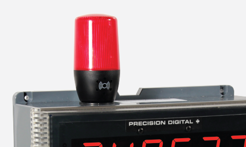
Light/Horn
The light/horn hole is on the top-left of the enclosure.
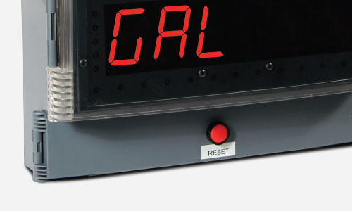
Button
The button is centered on the cover of the enclosure below the display.
Connections
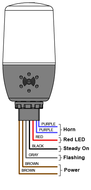
MOD-PD2LH Models
Connections shown for a red light model. For other MOD-PD2LH models, the red wire is the color of the light. Connect the red and black wires for a Steady On light and red and gray wires for Flashing light.
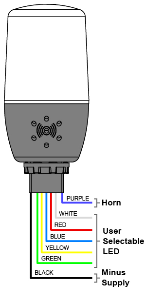
MOD-PD2LH5CB1
Connect the LED color to the plus supply and the black wire to the minus supply to turn the LED on. Be aware of limitations for applications requiring different color lights for different alarm conditions.
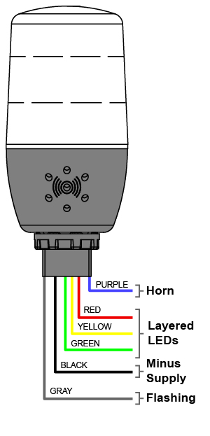
MOD-PD2LH3LCB1-RYG
Connect the LED color to the plus supply for a Steady On light and LED color and gray wires to the plus supply for Flashing light. The black wire should be connected to the minus supply.
Applications
There are a wide variety of ways these light/horn devices can be controlled by Precision Digital meter's relays to satisfy visual and audible alarm applications. Feel free to contact tech support to discuss your particular application. The following examples illustrate some typical applications.
MOD-PD2LH Models
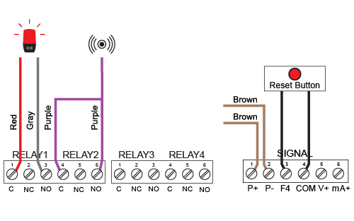
PD2 meter with internal transmitter power supply connections shown
The MOD-PD2LH models are the simplest devices in the series and are made up of a single-color light and horn. A typical way to use the MOD-PD2LH is to program the meter so that the horn can be silenced at any time via a button connected to the meter's digital input or via the F3 front panel button, and the light to reset automatically when the alarm clears:
| Relay | Connected to | Default Reset |
| 1 | Flashing Light(1) | Auto reset |
| 2 | Horn | Silence with Button at any time |
| 3 | User Device | As user desires |
| 4 | User Device | As user desires |
| 1 Light can be wired to flash or stay steady on. | ||
MOD-PD2LH5CB1
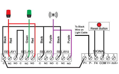
PD2 meter with internal transmitter power supply connections shown
The MOD-PD2LH5CB1 shows one color at a time and the light color (red, green, yellow, blue or white) is determined by which wires are connected to power through the meter’s relays. A typical application for the MOD-PD2LH5CB1 might involve lighting up the red light to indicate high and low alarms and the green light to indicate everything is OK using a Precision Digital meter's four internal relays:
| Relay | Purpose | Light/Horn | Action |
| 1 | Low alarm | Red light | Auto |
| 2 | All OK | Green light | Auto |
| 2 | High alarm | Red light | Auto |
| 3 | Low alarm | Horn | Latch |
| 4 | High alarm | Horn | Latch |
MOD-PD2LH3LCB1-RYG
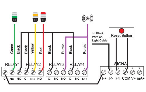
PD2 meter with internal transmitter power supply connections shown
The MOD-PD2LH3LCB1-RYG can light up red, yellow or green lights as determined by which wires are connected to power through the meter's relays. A typical application for the MOD-PD2LH3LCB1-RYG (and the default factory setting) might involve lighting up the green light to indicate everything is OK, the yellow light to indicate a High warning, and the red light to indicate a High alarm. The Horn will also sound at both the Warning and High alarms and can be manually reset at any time via a button connected to the meter's digital input or via the F3 front panel button:
| Relay | Purpose | Light/Horn | Action |
| 1 | All OK | Green light | Auto |
| 2 | Warning | Yellow light | Auto |
| 2 | High alarm | Red light | Auto |
| 3 | Warning | Horn | Latch |
| 4 | High alarm | Horn | Latch |
Watch the Light/Horn Video
You may be interested in
Light/Horn Enclosure Modification
What's included:
- Light/Horn
- Button and 9 Labels
- Hole Drilling on Enclosure
⚠ Meter and enclosure sold separately. User installation and wiring required.





 MOD-PD2LH Models Using Internal Power Supply
 MOD-PD2LH5C Models Using Internal Power Supply
 MOD-PD2LH3LC-RYG Models Using Internal Power Supply
 MOD-PD2LH Models Using External Power Supply (
 MOD-PD2LH5C Models Using External Power Supply (
 MOD-PD2LH3LC-RYG Models Using External Power Supply (
 MOD-PD2LH Models Using External Power Supply (
 MOD-PD2LH5C Models Using External Power Supply (


