A common application for Precision Digital's ProVu series is for monitoring & alarming. In these applications, the meter is not used as a primary controller, but a safety device. As such, Precision Digital added another safety feature called Interlock Relay. This feature allows a process to use very low input signals or dry contacts to signal the ProVu that an event occurred that should cause one or more "normally opened" (N/O) assigned relay contacts to "open". While its main purpose is to remove power from a final control element in the event of a safety violation, it is likely that this feature will be used for many more applications as its configuration is very versatile.
Any, or all, of up to 8 digital inputs can cause any of the four main relays to energize with a closed contact or 5 volt signal present at the assigned digital input(s). This feature is designed to be a fail-safe circuit. This means that the interlock relay will "de-energize" with a failure (open digital input loop, loss of digital input signal, loss of power to the meter, etc.). This is called a "Normally Energized Mode" or fail-safe. The relay indicator will flash when the interlock relay is "de-energized" alerting the perator of the safety violation.
The most common configuration of this would be to have a loop of safety contacts in series. The wiring and contacts would carry no more than 5 volts at a low 3.5 mA (approx. - see Figure 1). This loop would be connected to a single logic input which in turn would control a single interlock relay (see Figure 2 below).
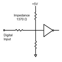
Figure 1
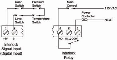
Figure 2
However, the "load" may be 3-phase. In that case, it may be preferable to have one safety input loop, but to trigger two, or even three, interlock relays. Then again, instead of three phase power, one might want to shut down multiple loads. So there is significant flexibility.
The reason for the multi-input/output capability is to provide the capability of multi-action depending upon the violation type or zone. For example, a user may want to open or close a valve when a first level limit switch is opened, and shut-down a pump when a second level limit switch opens in any of 2 tanks. In this case, one interlock relay would be wired to the valve, while the other would be wired to the pump (see Figure 3 below).

Figure 3
To configure an interlock relay for the above example, we would follow the following steps.
- Under Setup/Relay 1 the Action (Act 1) would be set to off (OFF).
- Under Setup/Relay 2 the Action (Act 2) would be set to off (OFF).
- In the Advanced menu under User (uSEr) set D1 input (D1 I) to Force On 1 (F On 1)
- In the Advanced menu under User (uSEr) set D2 input (D1 2) to Force On 2 (F On 2)
If a different digital input & relay output is used for each safety switch, then the user has the advantage of identifying the violating input by observing which relay indicator is flashing on the front panel. Since the ProVu offers up to 8 relays, there is plenty of capability.
Please refer to the manual when configuring interlock relays.
Remember, ultimately, it is up to the system designer to provide for the safe operation of a process. But certainly, no single event should make the difference between a safe situation and a catastrophe. Interlock relays can provide another level of personnel and equipment safety if configured correctly.
Related Products: PD6000, PD6060, PD6100, PD6200, PD6210, PD6300, PD6310, PD7000
Disclaimer: The information contained in this document is subject to change without notice. Precision Digital makes no representations or warranties with respect to the contents hereof; and specifically disclaims any implied warranties of merchantability or fitness for a particular purpose.