

Features
- NEMA 4X, IP67 Loop-Powered Field-Mount Process Meter
- 4-20 mA Input
- 1.0" (25.4 mm) 3½ Digits LCD Display; -1999 to 1999
- 1 V Drop
- HART® Protocol Transparent
- Operates from -40 to 85°C (-40 to 185°F)
- Operates from -40 to 40°C (-40 to 104°F) for Canadian Installations
- Zero & Span Potentiometer Adjustments for Easy Field Scaling
- Plastic NEMA 4X, IP67 Enclosure
- FM Approved & CSA Certified as Intrinsically Safe & Nonincendive
- Conformal Coated PCBs for Dust and Humidity Protection
- One ½" Conduit Hole (Rear, Top, Bottom or None)
- Pipe & Panel Mounting Kits
- Stainless Steel Tag Available
Why Use Loop-Powered Meters?
The most basic decision a user wishing to display a 4-20 mA signal on a digital display has to make is: should the meter be powered by line voltage or should it be powered by the 4-20 mA loop?
There are three main benefits of using loop-powered devices:
- No additional power required
- Easy wiring
- Additional digital displays can easily be added in the same loop
The following diagram illustrates how a loop-powered meter is wired. Notice there are only two connections made to the meter.
For more information on loop-powered meters, check out Fundamentals of Loop-Powered Devices and Loop-Powered vs Line-Powered Meters white papers.
Overview
The PD686 is an FM Approved, CSA Certified intrinsically safe and nonincendive, NEMA 4X, IP67 loop-powered indicator that is easy to install and program. It can be seen from considerable distance and even in bright sunlight. The fact that this meter is loop-powered means that there is no need to run additional, costly power lines into a hazardous area. The meter gets all of the power it needs from the 4-20 mA loop and its 1 V drop results in a minimal burden on the loop. The meter features a wide -40 to +85°C operating temperature range and is available with a ½" conduit hole in a location of your choice for easy installation. Calibration is a quick two-step process involving the adjustment of only high and low, non-interacting potentiometers.
Except where noted all specifications apply to operation at +25°C.
| Input | 4-20 mA @ 30 VDC maximum | |
| Display | 1.0" (25.4 mm) LCD, 3½ digits; -1999 to +1999 | |
| Accuracy | ±0.1% FS ±1 count | |
| Approvals | FM Approved & CSA Certified as intrinsically safe
with entity, for use in Class I, II and III, Division
1, Groups A, B, C, D, E, F, & G; T4; hazardous
locations. Nonincendive for use in Class I, Division 2, Groups A, B, C and D. Suitable for use in Class II and III, Division 2, Groups F and G FM certificate number: 3016598. CSA certificate number: 1111348 | |
| Additional FM Approvals | Intrinsically Safe, Class I, Zone 0, AEx ia IIC T4 | |
| Entity Parameters | Ui = 30 V, li = 175 mA, Ci = 0 μF, Li = 0 μH, Pi = 1.3 W See Control Drawing LIM686-2 (Dwg No 1155) for complete installation instructions. | |
| Decimal Point | User selectable | |
| Calibration | Two-step; non-interacting zero and span | |
| Calibration Range | 4 mA input: -1000 to +1000; 20 mA input: between 20 and 2000 counts > 4 mA display | |
| Display Update Rate | 2.5/second | |
| Maximum Input Current | 30 mA | |
| Maximum Voltage Drop | 1 V @ 20 mA | |
| Operating Temperature | -40 to 85°C Canadian installations: -40 to 40°C. | |
| Storage Temperature | -40 to 85°C | |
| Relative Humidity | 0 to 90% non-condensing. Printed circuit boards are conformally coated. | |
| Enclosure | Impact-resistant glass filled polycarbonate body, color: gray; impact-resistant clear polycarbonate cover; NEMA 4X, IP67 | |
| Connections | Removable screw terminals accept 12 to 26 AWG | |
| Conduit Hole | One ½" conduit hole provided, see Ordering Info. | |
| Overall Dimensions | 5.51" x 3.15" x 2.56" (W x H x D) (140 mm x 80 mm x 65 mm) | |
| Weight | 12 oz (340 g) | |
| Warranty | 2 years parts and labor. See Warranty Information and Terms & Conditions on www.predig.com for complete details. | |
Connections
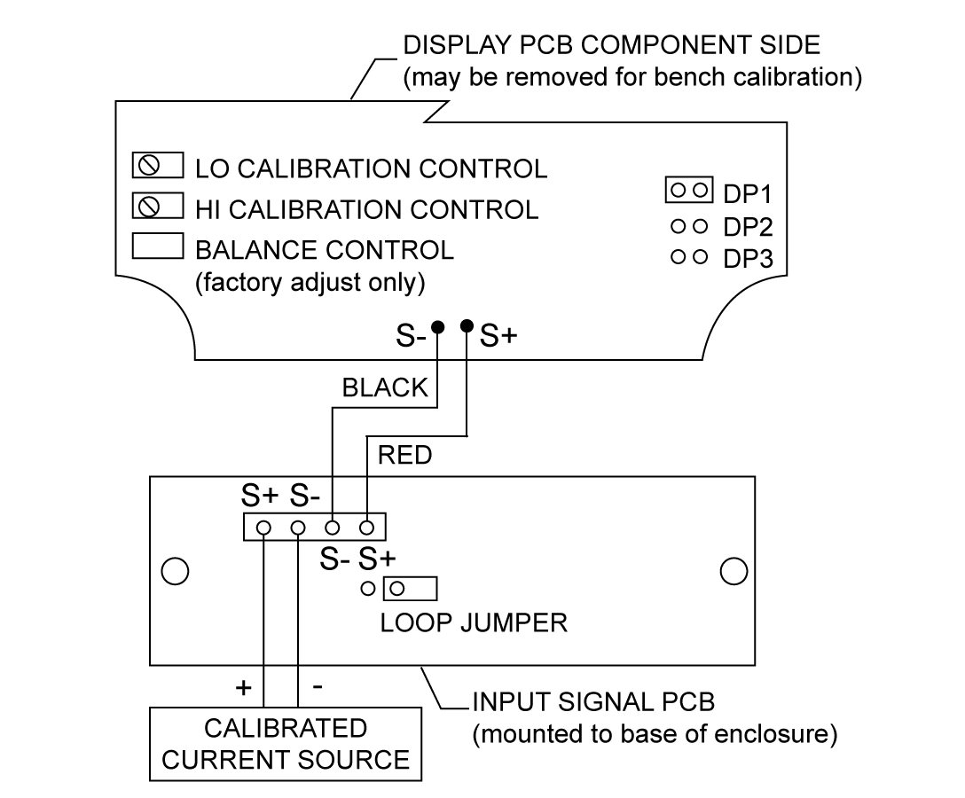
Calibrator Connected to Input Signal PCB
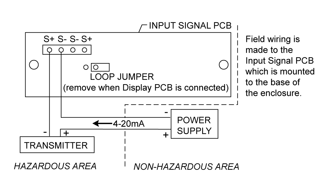
Control Loop Connected to Input Signal PCB
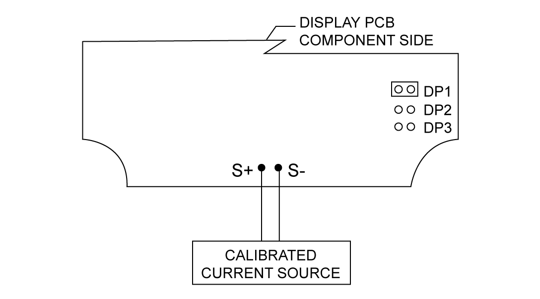
Calibrator Connected to Display PCB
The display PCB may be removed from the enclosure for bench calibration. Loop Jumper must be installed on Input Signal PCB to maintain loop.
Dimensions
Units: Inches (mm)
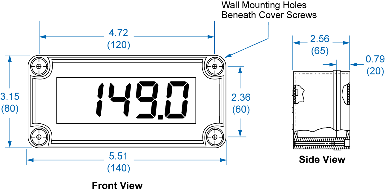
Dimensions and Wall Mounting Information
Pipe Mounting Kit
The PDA6845-SS is a stainless steel pipe mounting kit with two mounting holes. It provides all of the necessary hardware to mount the PD686 to a 2" pipe.
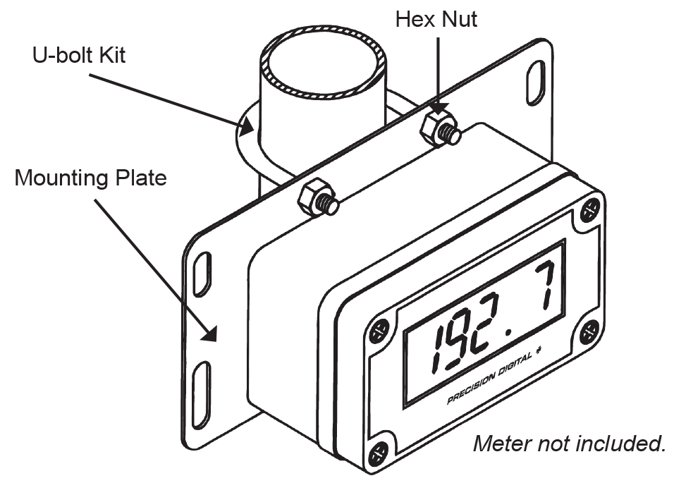
PDA6845-SS Pipe Mouting Kit
Panel Mounting Kit
The PDA6844 is a panel mounting kit for the PD686. It provides all of the necessary hardware to mount the PD686 meter to an equipment panel. This panel mounting kit is not intended to provide waterproof protection to the panel.
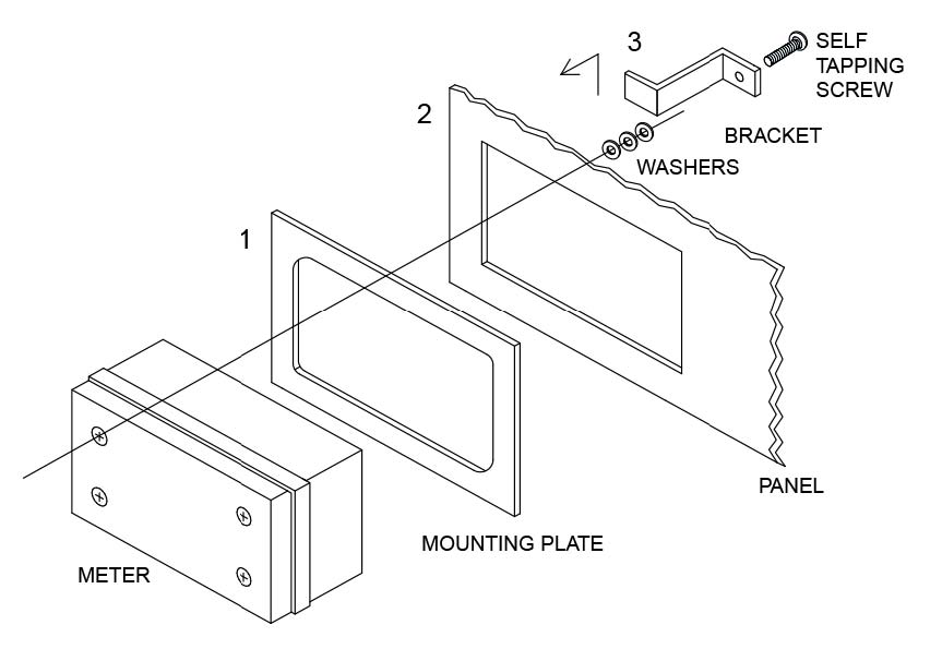
PDA6844 Panel Mouting Kit
Choose Your Options

Applicable Meter Types for PDC Enclosures
| Type A | Type B | Type C | Type D | Type E | Type F | Type G | Type H |
|---|---|---|---|---|---|---|---|
 |  |  |  |  |  |  |  |
| PD690 | PD542 PD543 | PD603 PD644 PD743 PD765 PD6602 PD6603 PD6604 PD6606 PD6607 PD6608 PD6622 PD6624 PD6626 PD6628 | PD138 PD154 PD158 PD520 | PD6000 PD6001 PD6060 PD6080 PD6081 PD6088 PD6089 PD6100 PD6200 PD6210 PD6262 PD6300 PD6310 PD6363 PD6400 PD7000 | PD530 | PD510 | PD420 |