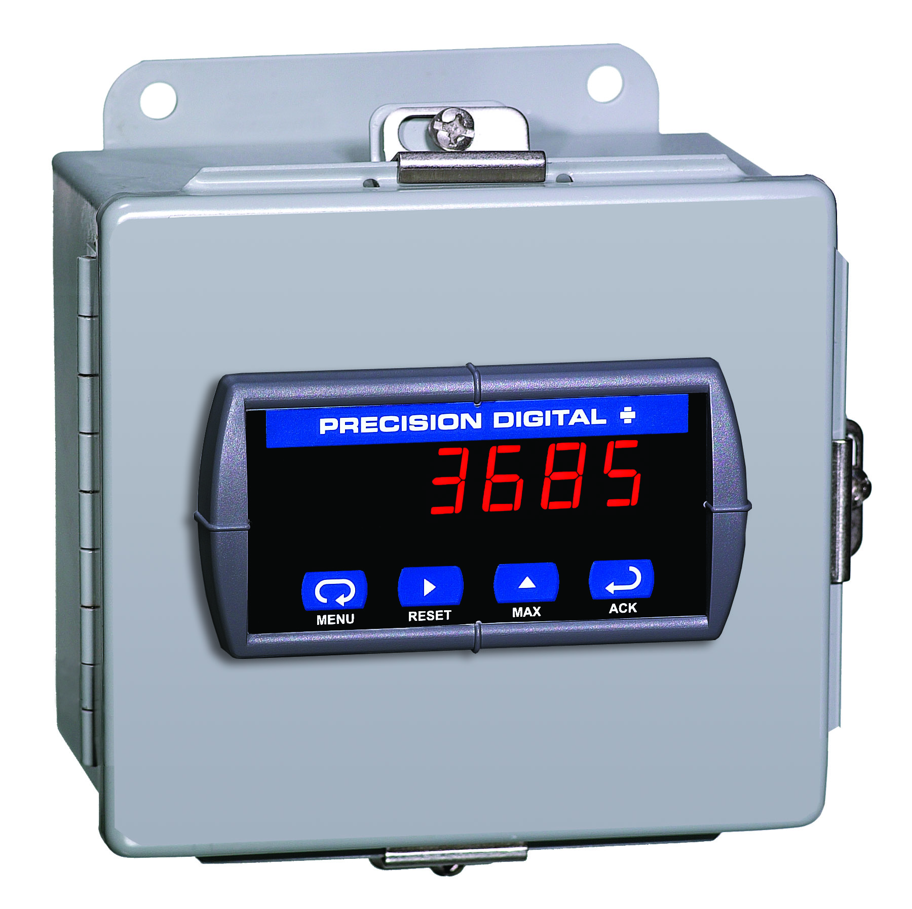
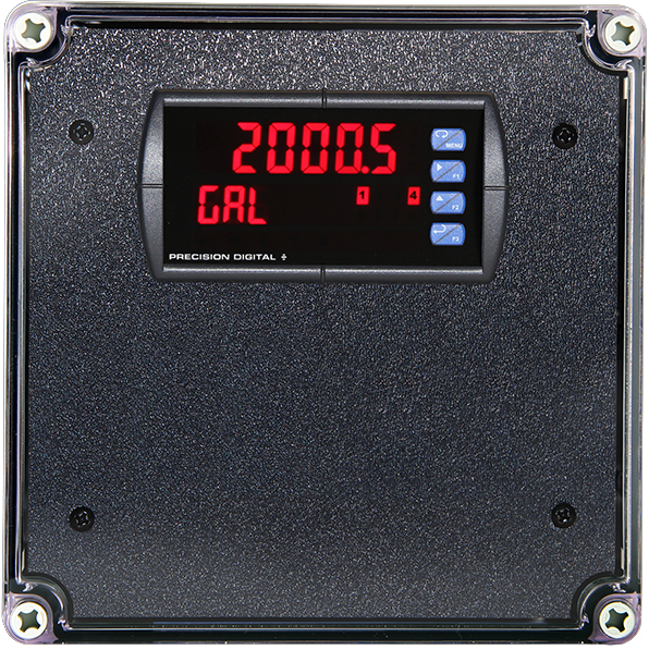
- 1/8 DIN Digital Panel Meter with NEMA 4X, IP65 Front
- 4-20 mA, ± 10 V, TC & RTD Field Selectable Inputs
- Easy Field Scaling in Engineering Units without Applying an Input
- Full 4-Digit Display, 0.56" (14.2 mm) or 1.20" (30.5 mm)
- Shallow Depth Case Extends Only 3.6" (91 mm) Behind Panel
- Isolated 24 VDC @ 200 mA Transmitter Power Supply Option (AC Powered Models Only)
- 2 Relays + Isolated 4-20 mA Output Options
- Free PC-Based MeterView Programming & Monitoring Software
- No Assembly Required
- Sunlight Readable Display
- Operating Temperature Range: -40 to 65°C (-40 to 149°F)
- UL & C-UL Listed. E160849; UL 508 Industrial Control Equipment
- Input Power Options: 85-265 VAC / 90-265 VDC or 12-36 VDC / 12-24 VAC
- Duplex Pump Controller with Alternation Capability
- External Contacts for Remote Button Operation (Trident X2 Only)
- USB, RS-232, & RS-485 Serial Communication Adapters Options
- Modbus RTU Communication Protocol Standard
- Copy Meter Settings to Other Trident Meters
- Password Protection
- Max/Min Display
- High & Low Alarms with Multiple Reset Actions
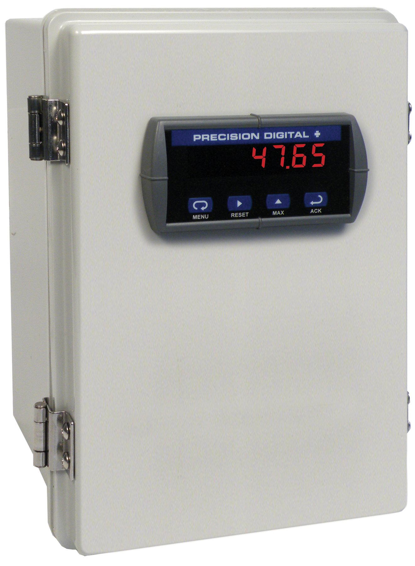
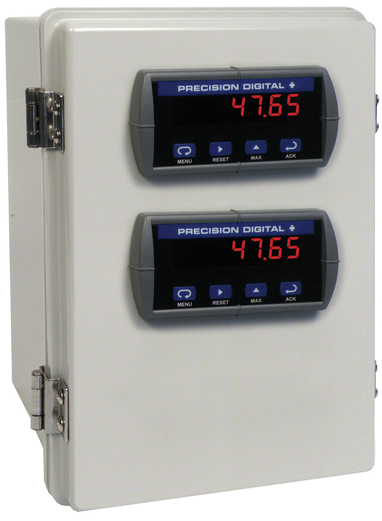
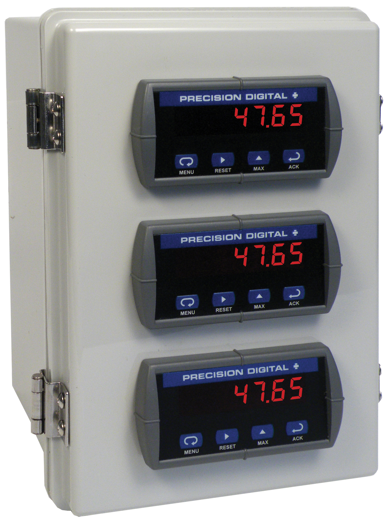
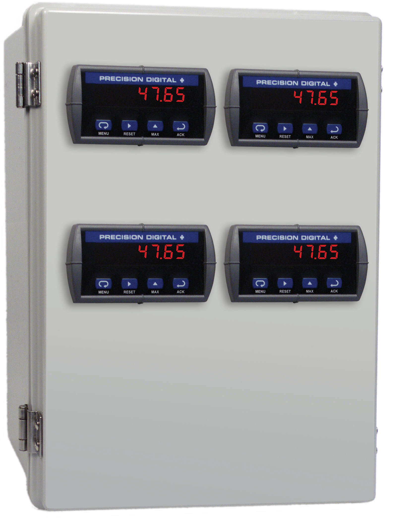
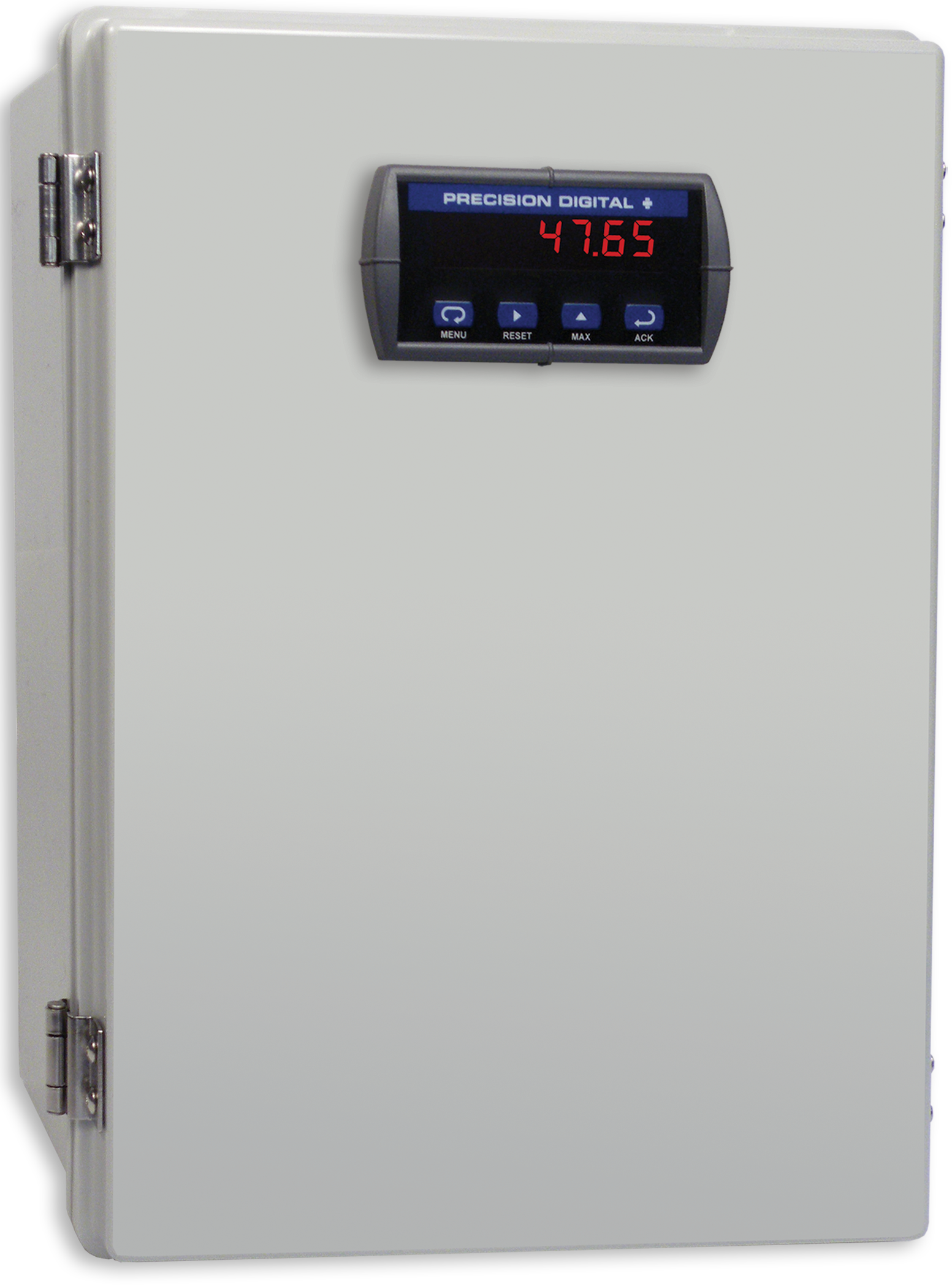
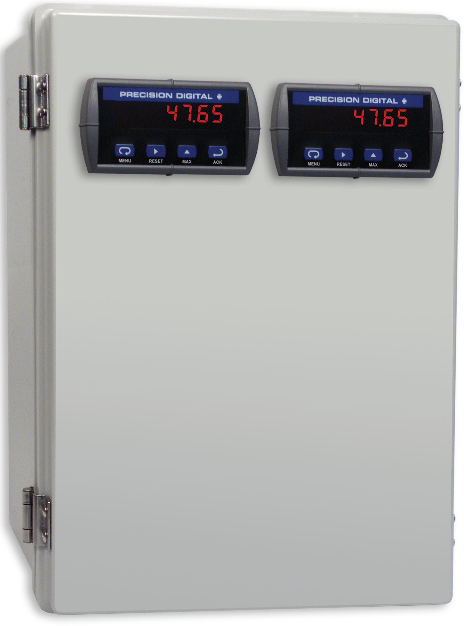
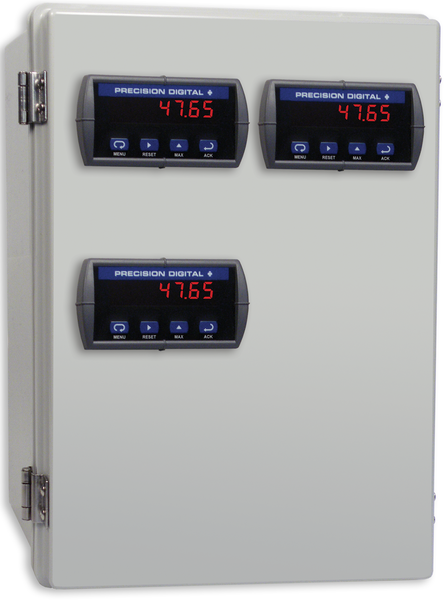
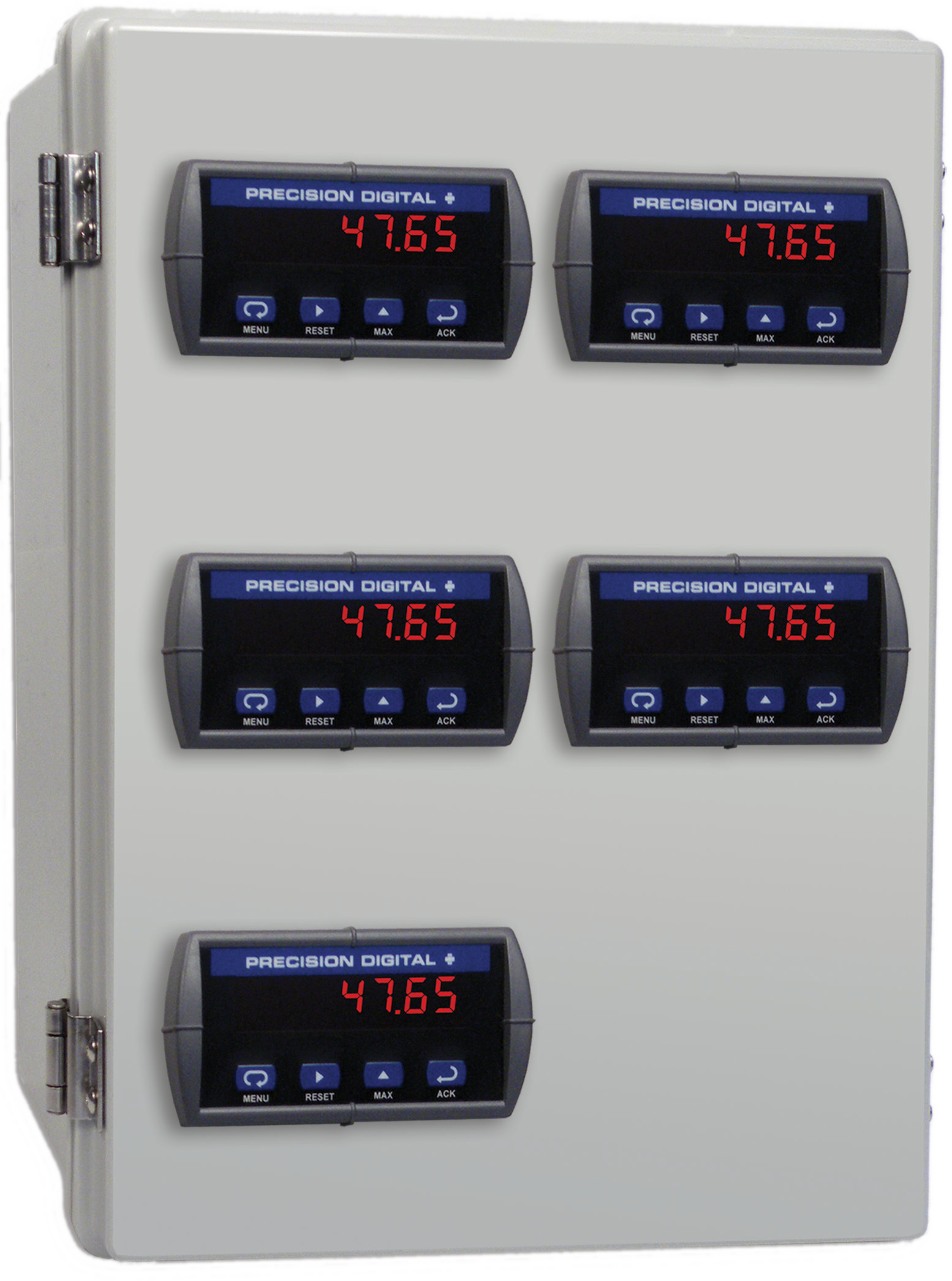
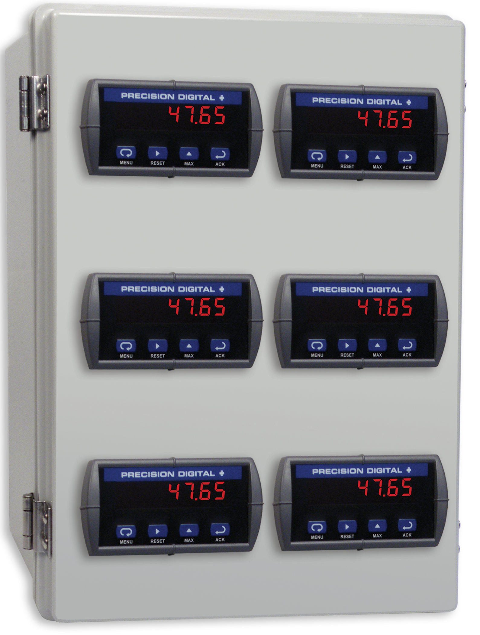
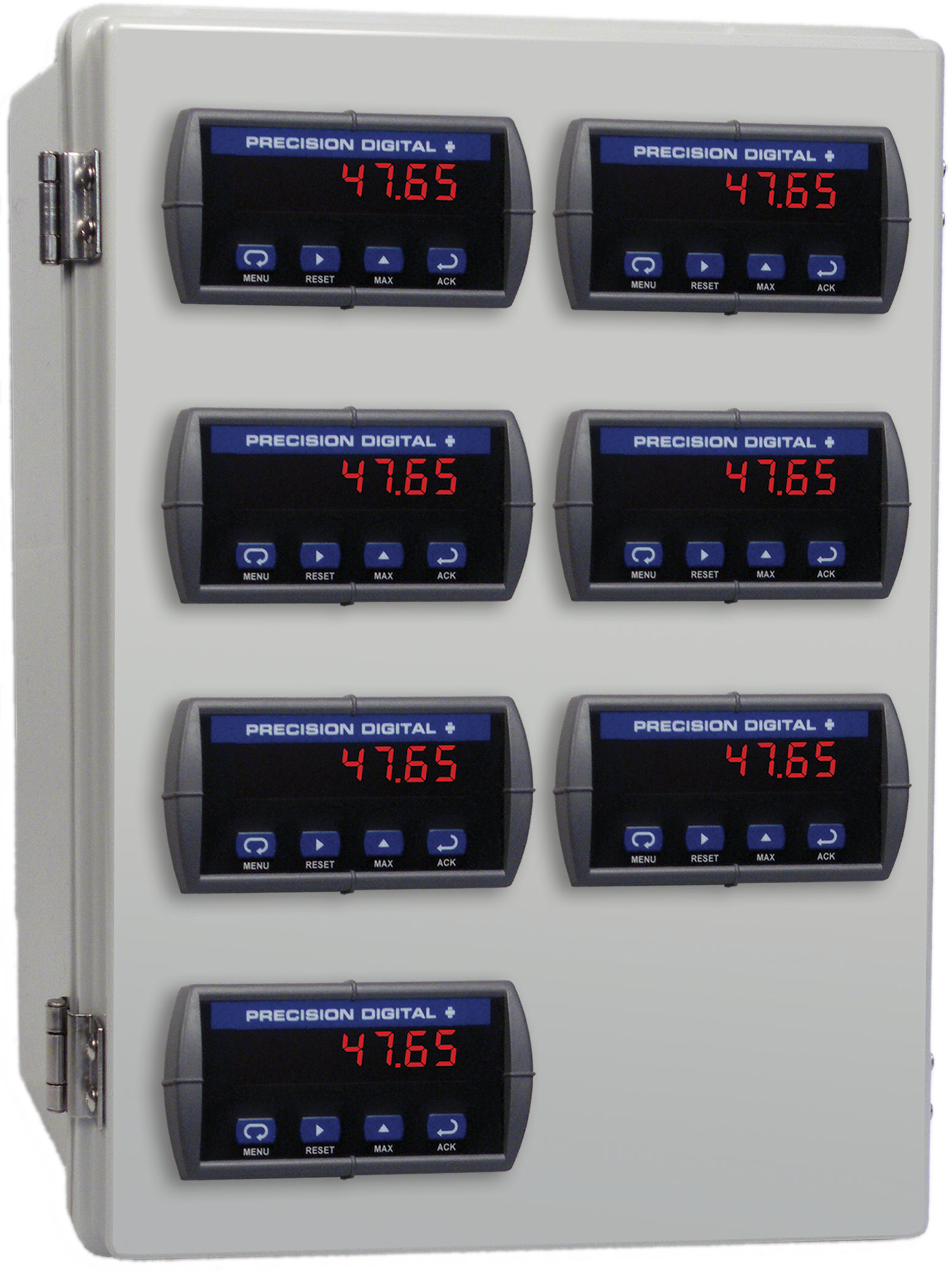
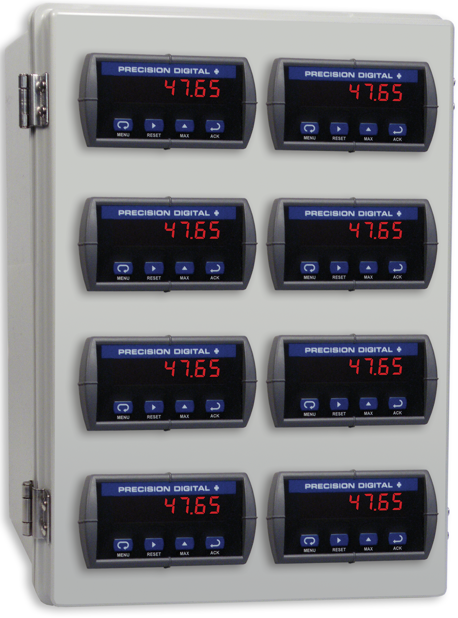
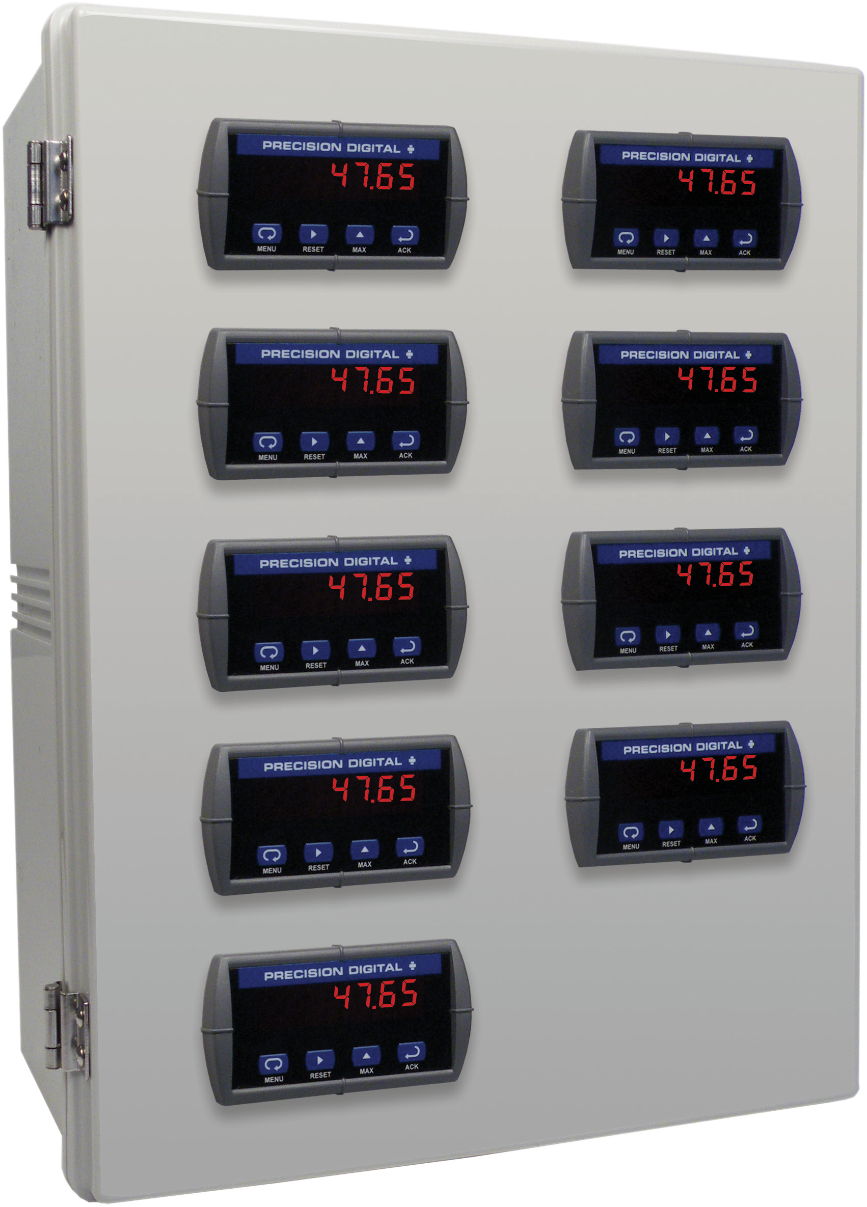
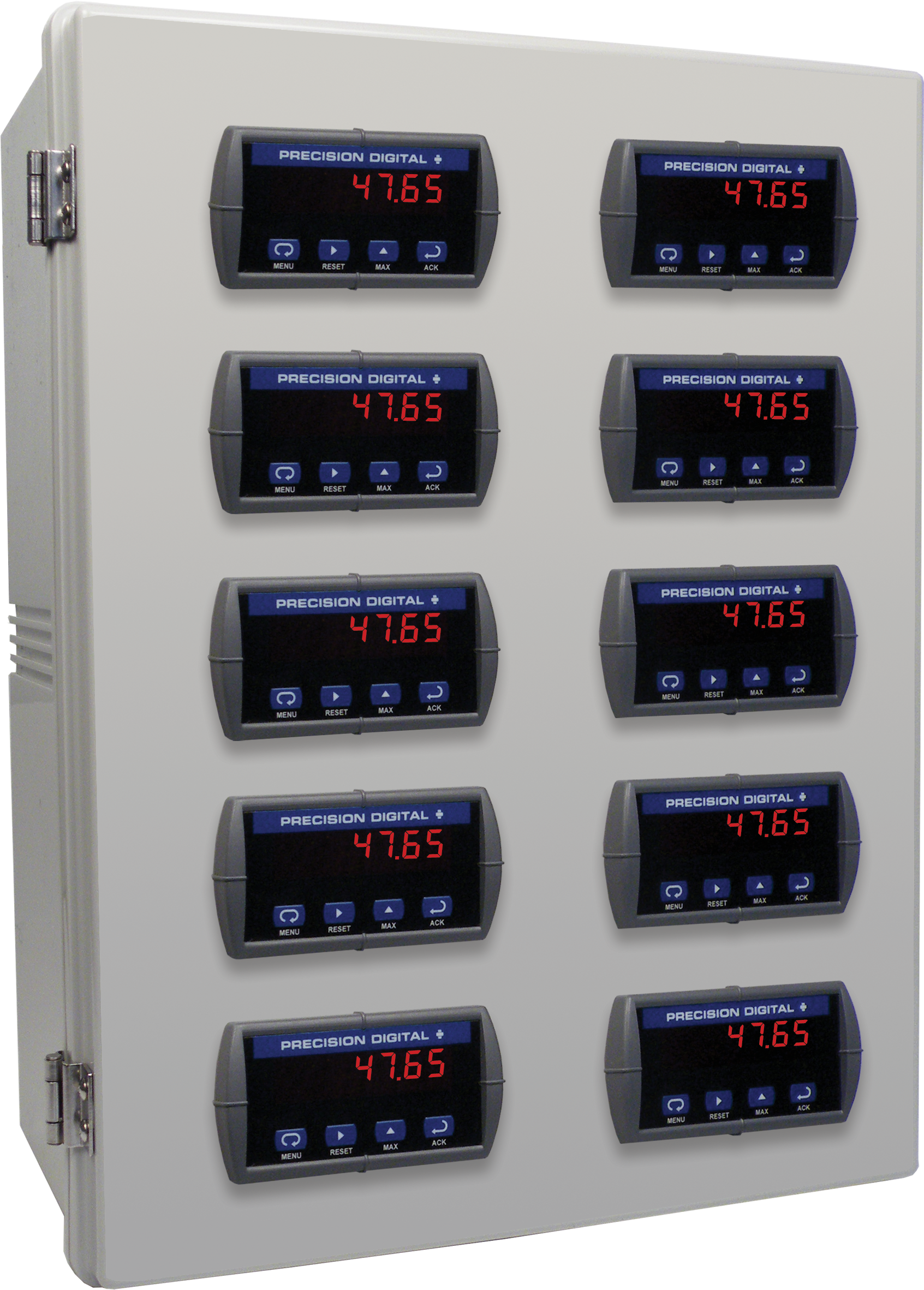
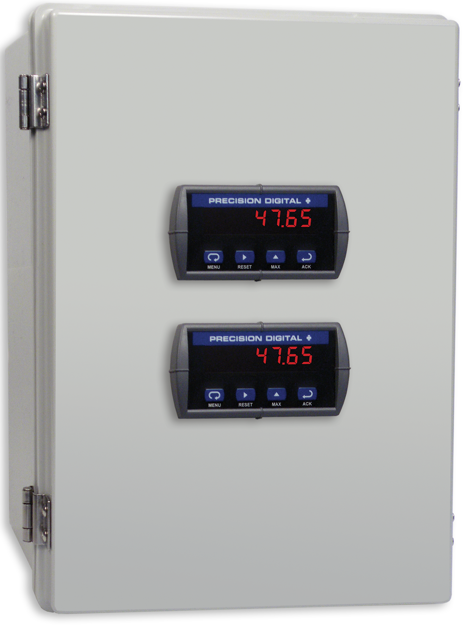
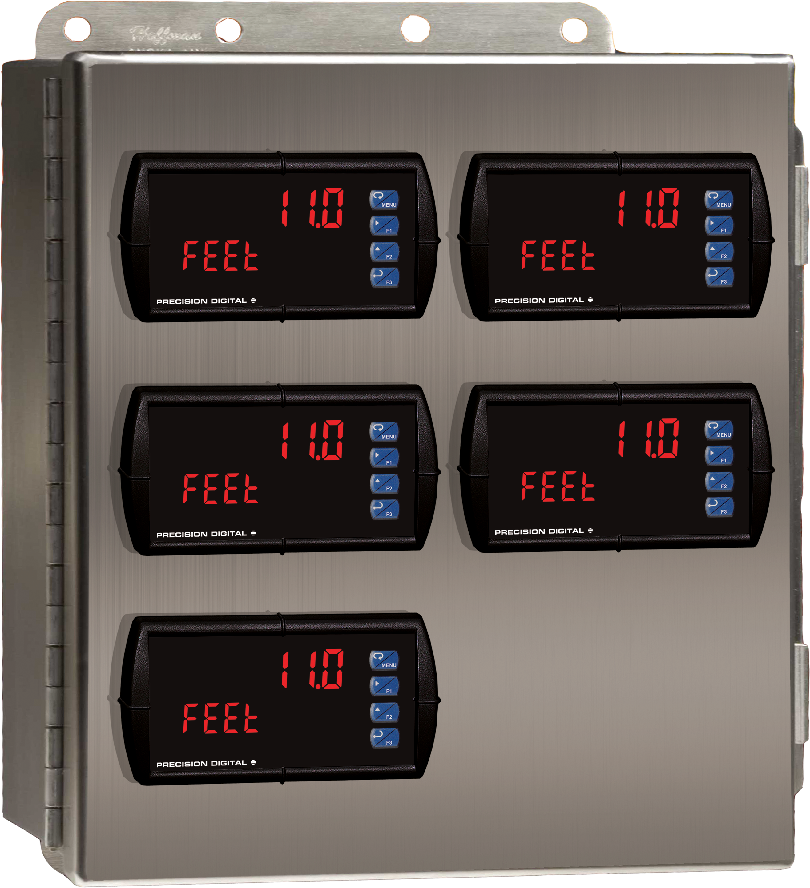
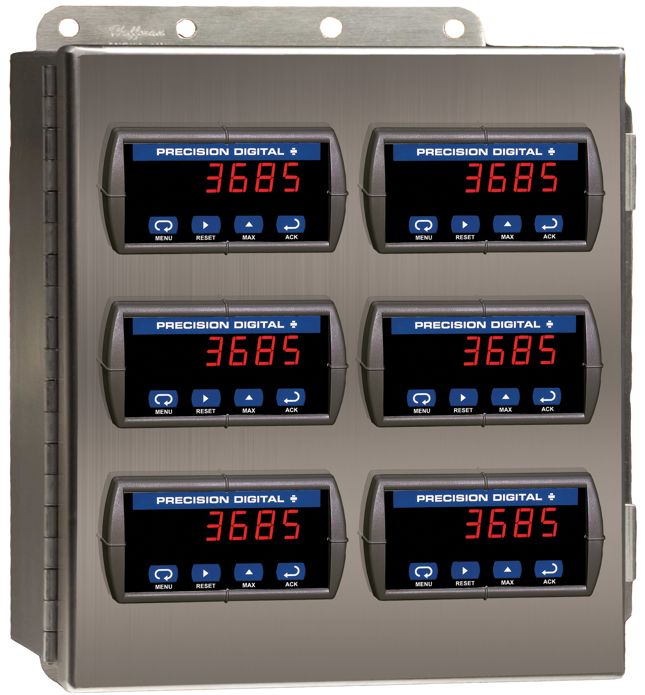
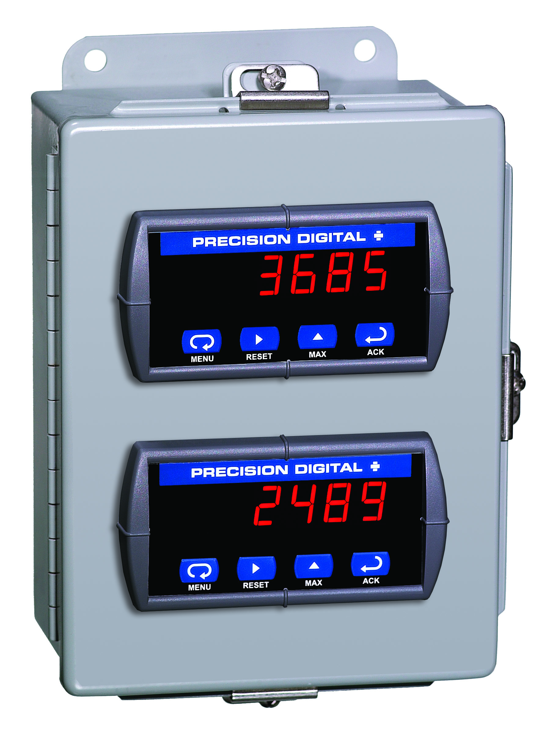
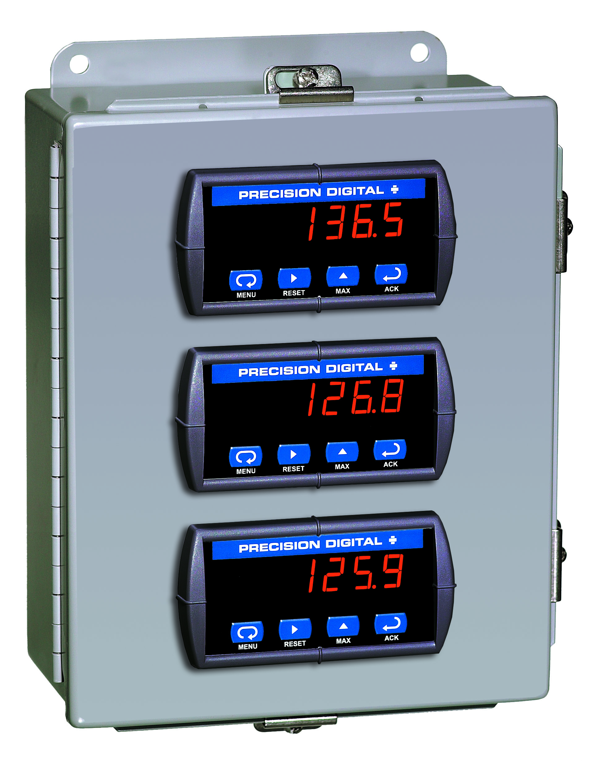
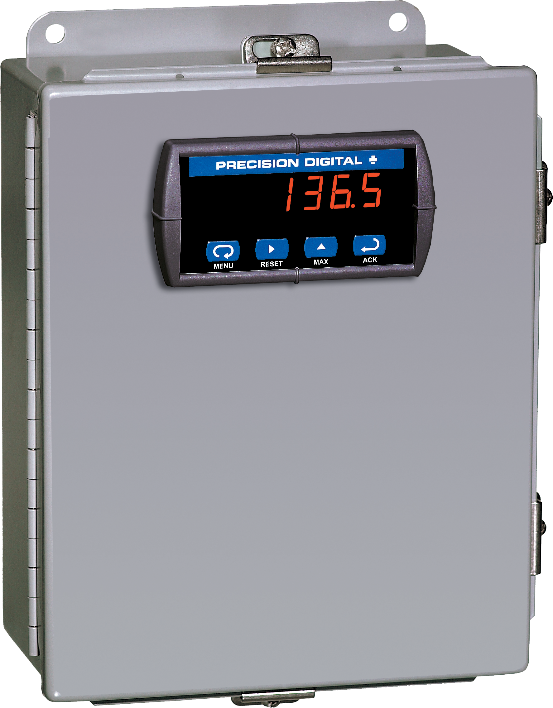
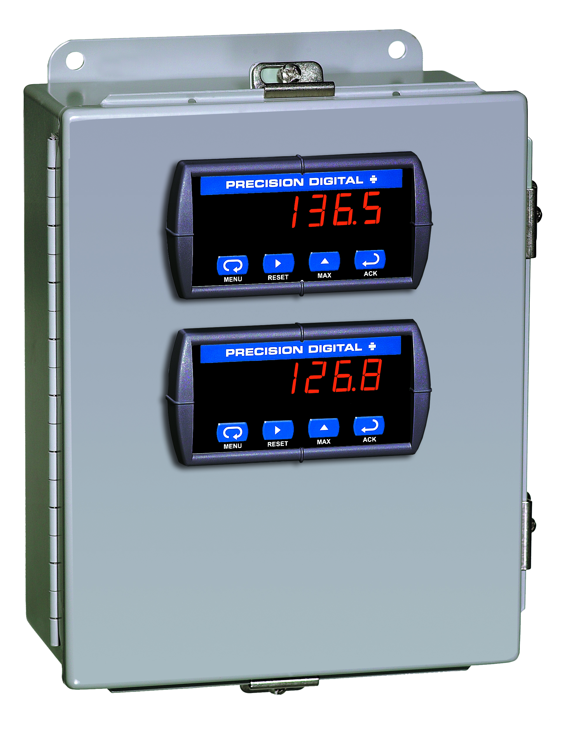
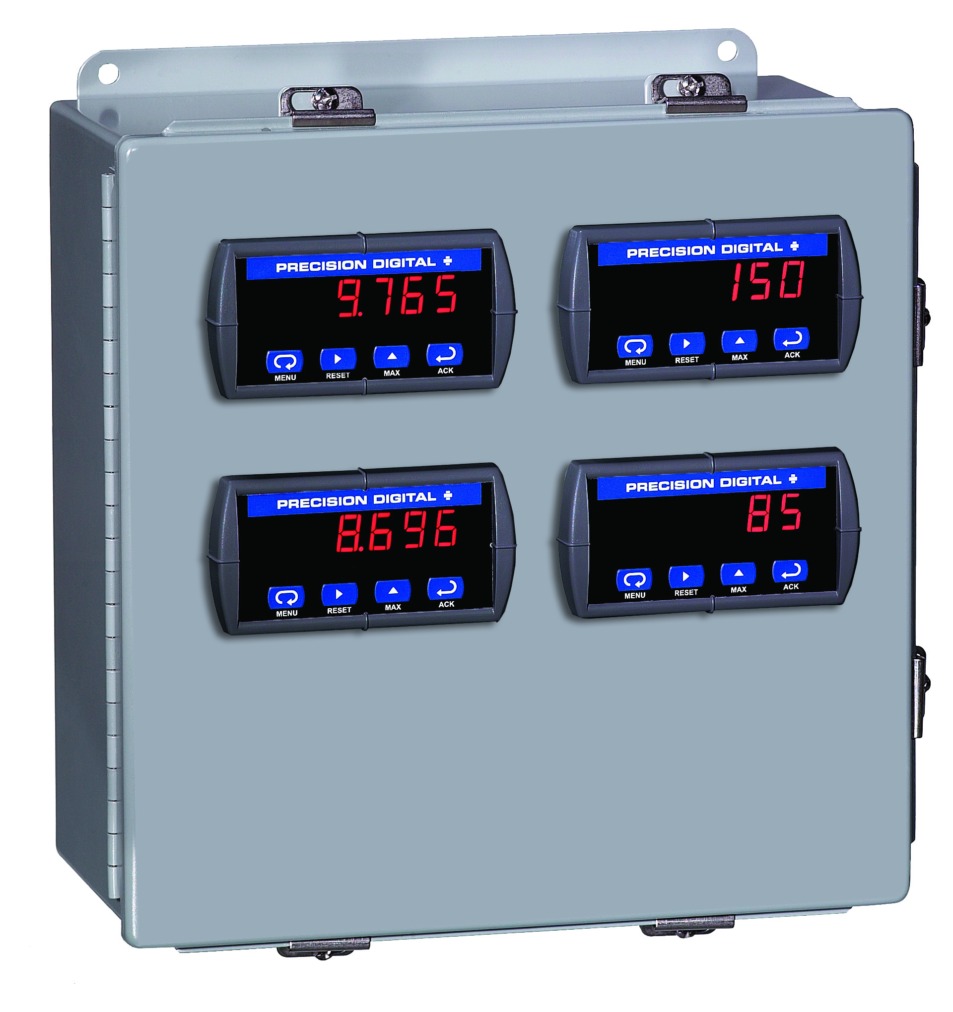
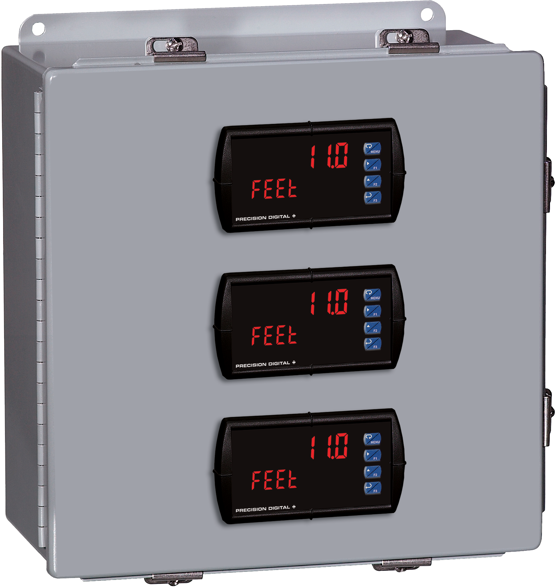
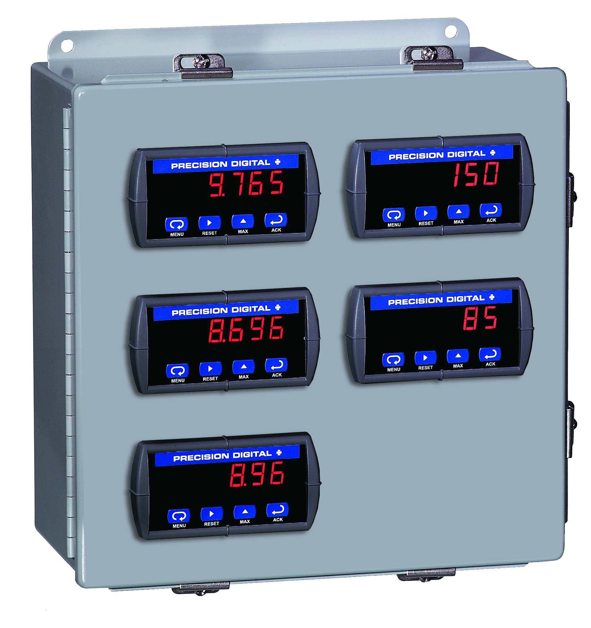
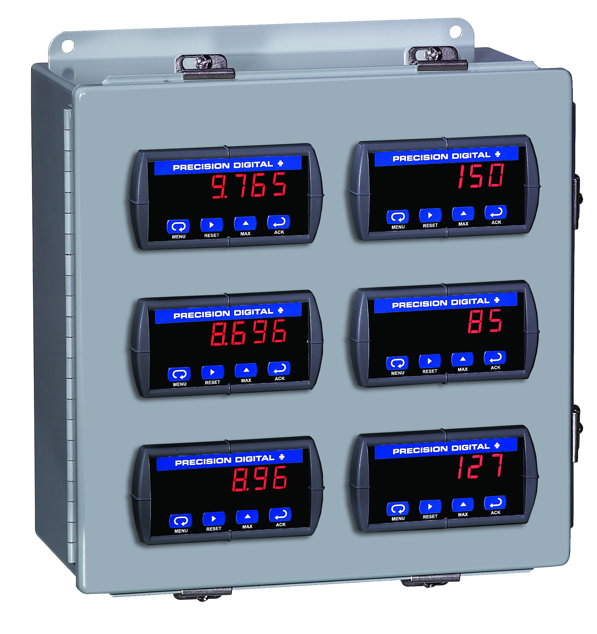
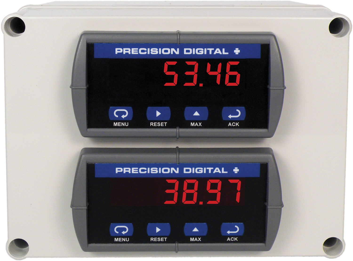
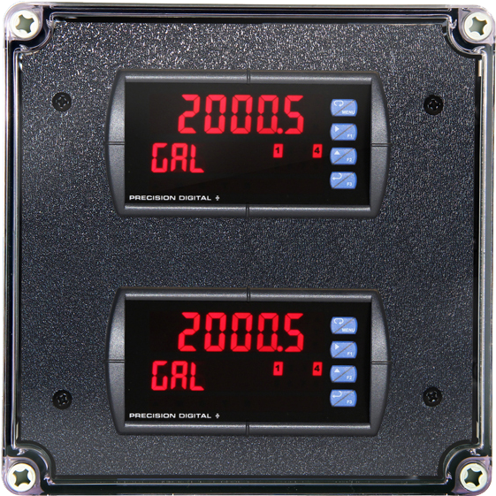
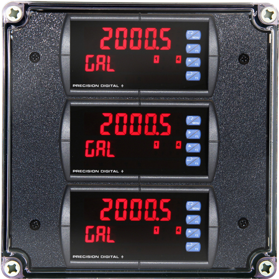
- Wide Assortment of NEMA 4X Enclosures for up to Ten Meters
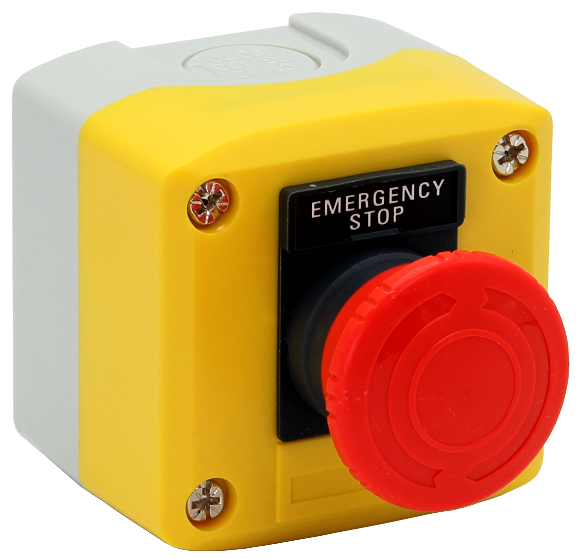
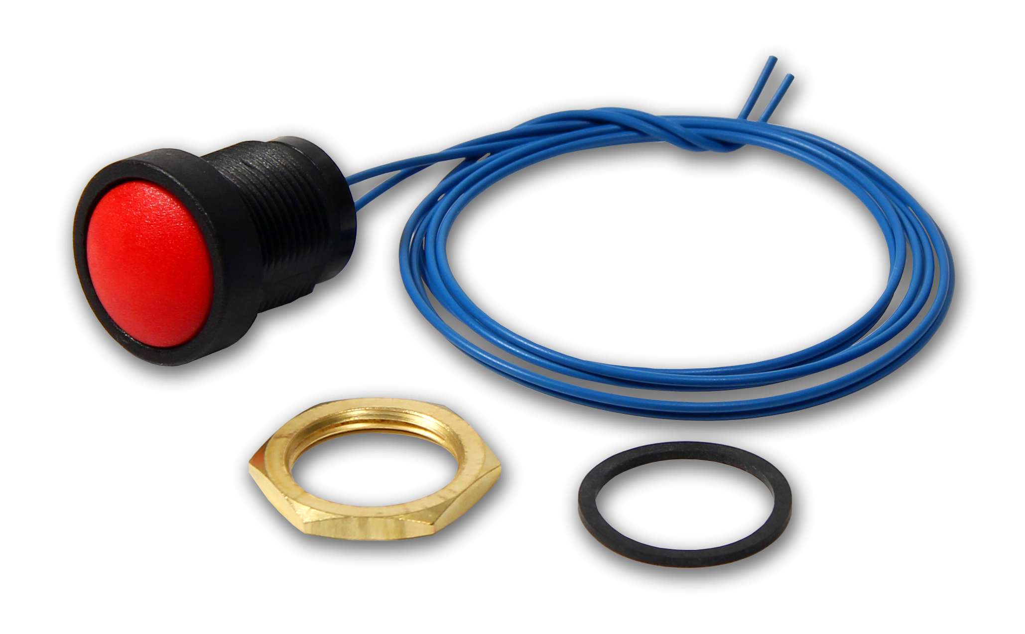
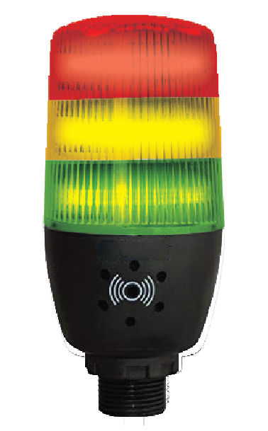
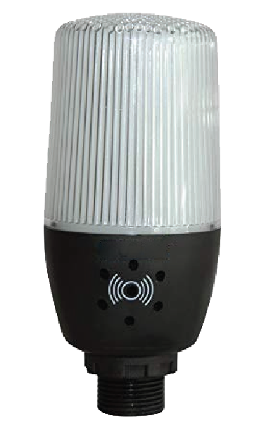
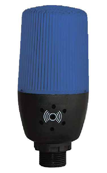
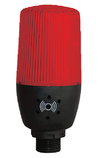
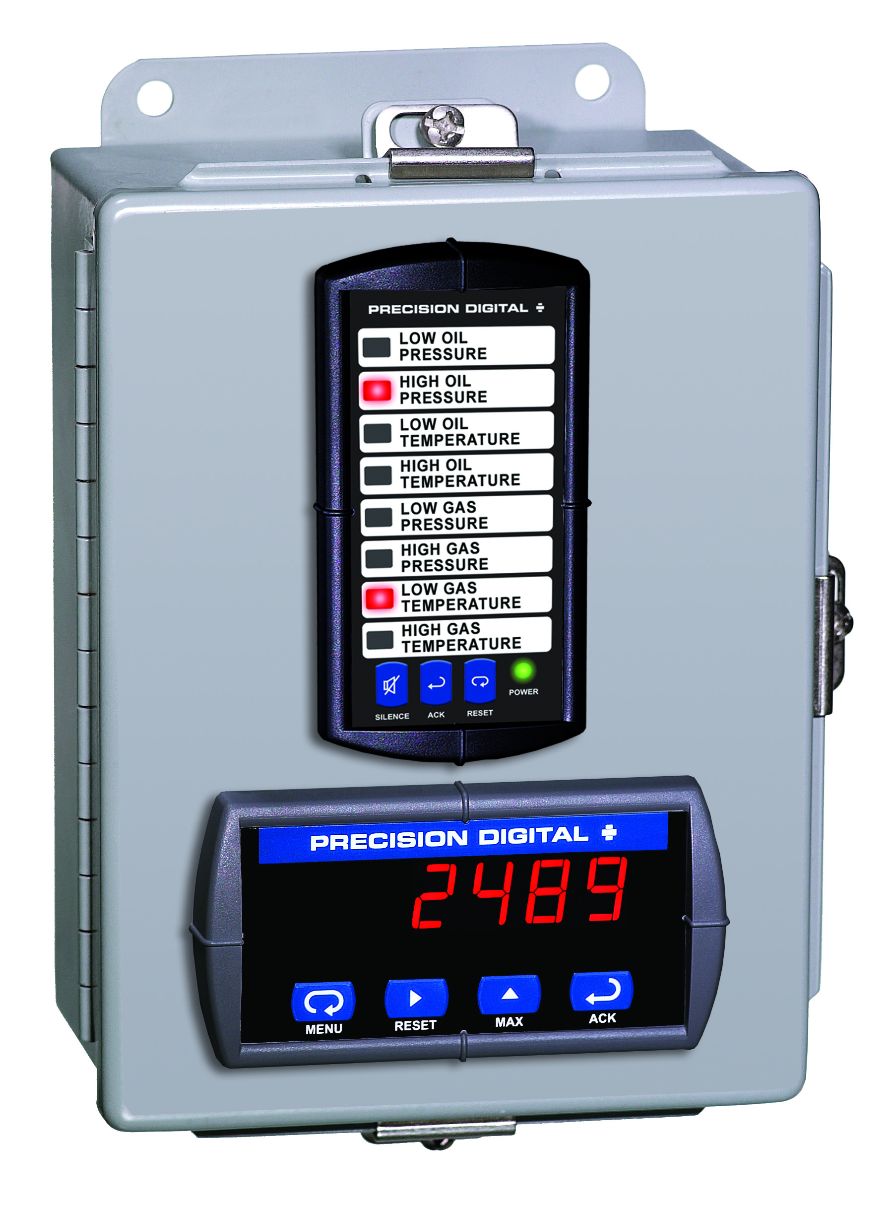
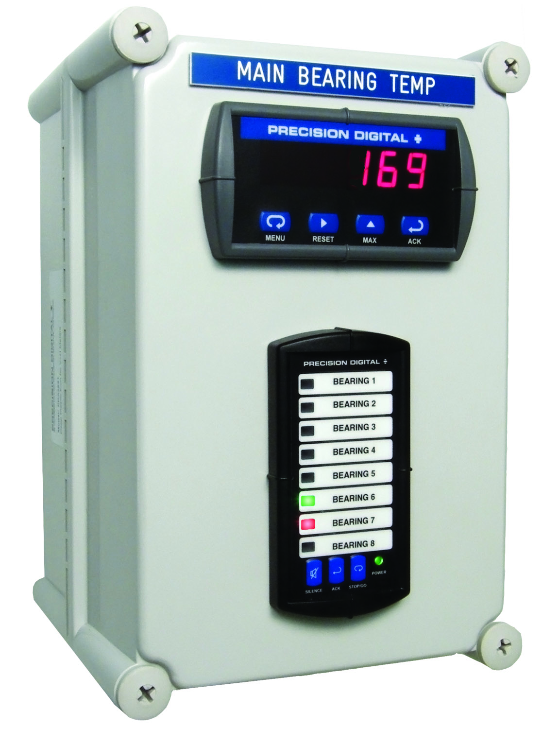
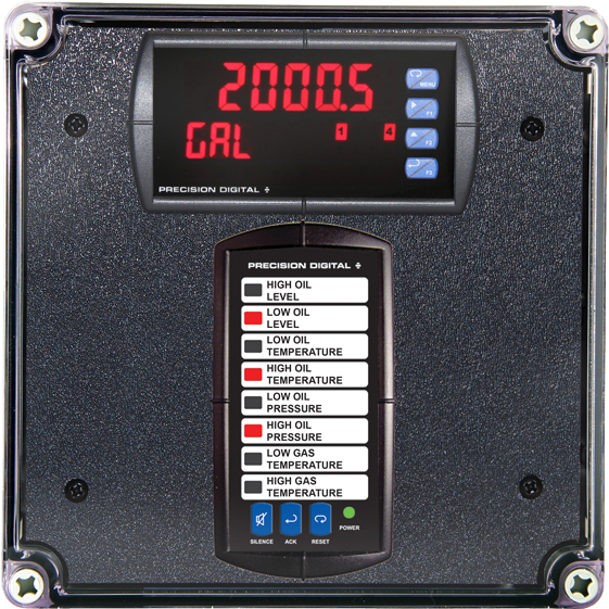
- Light/Horn & Button Accessory for Trident X2
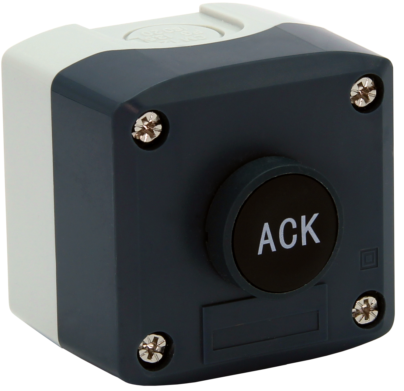
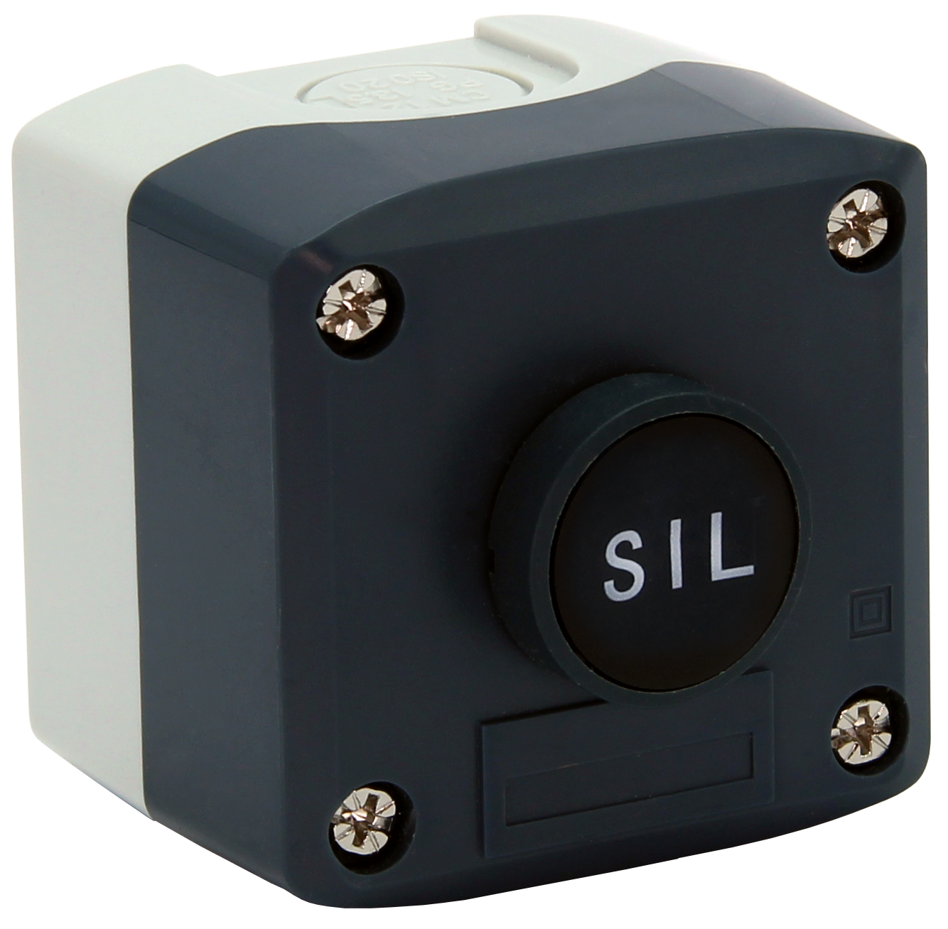
- Control Station Accessory for Remote Operation of Trident X2
- Stainless Steel Sun Hood Accessory Available
- 3-Year Warranty
** NEW IMPROVED WEB STORE! | All users must register for a new account. | Register now > **
BUY ONLINE TO SAVE TIME AND INCREASE ORDER ACCURACY!

Questions? (508) 655-7300
- Accessories
- Annunciators & Scanners
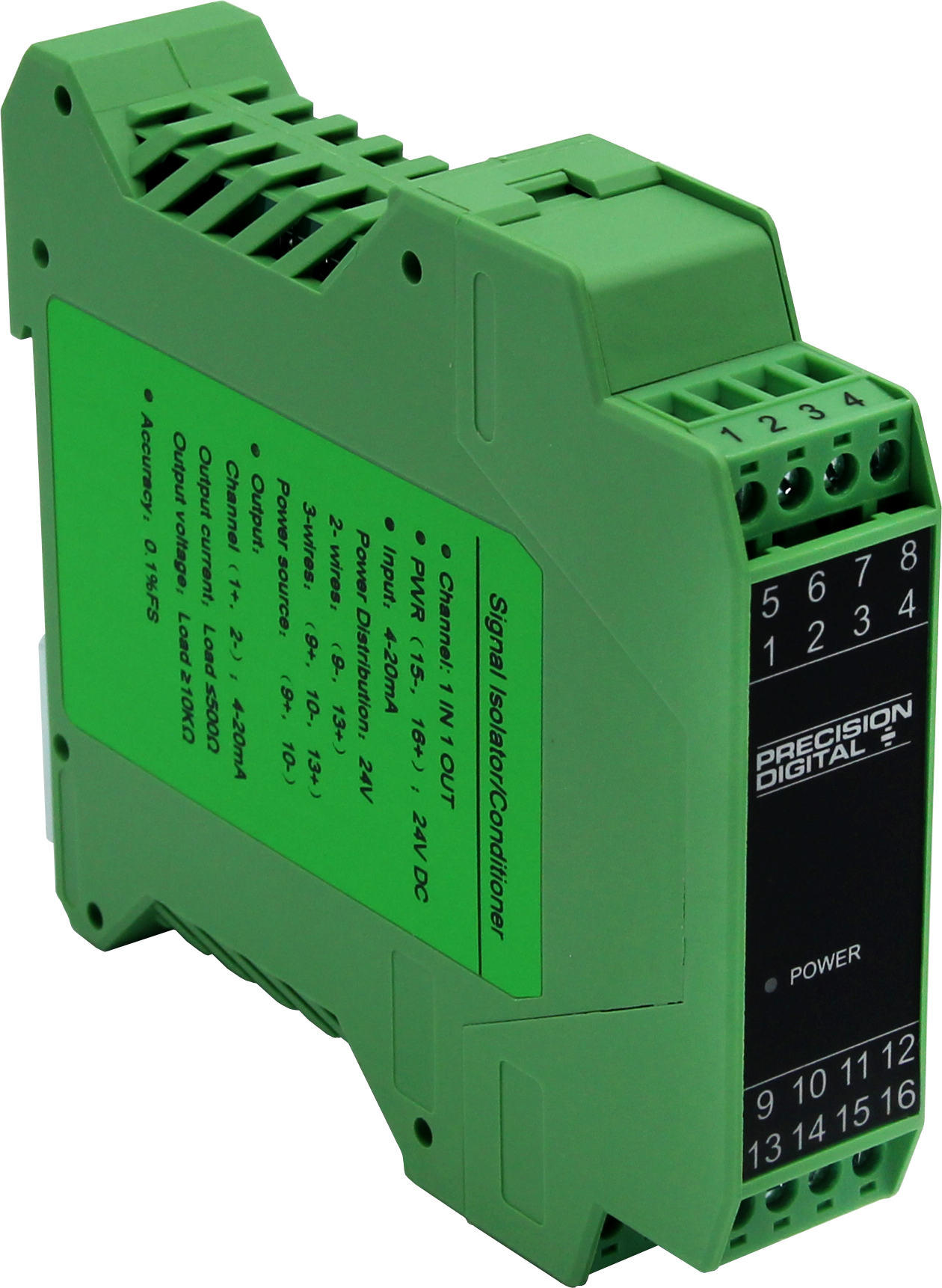
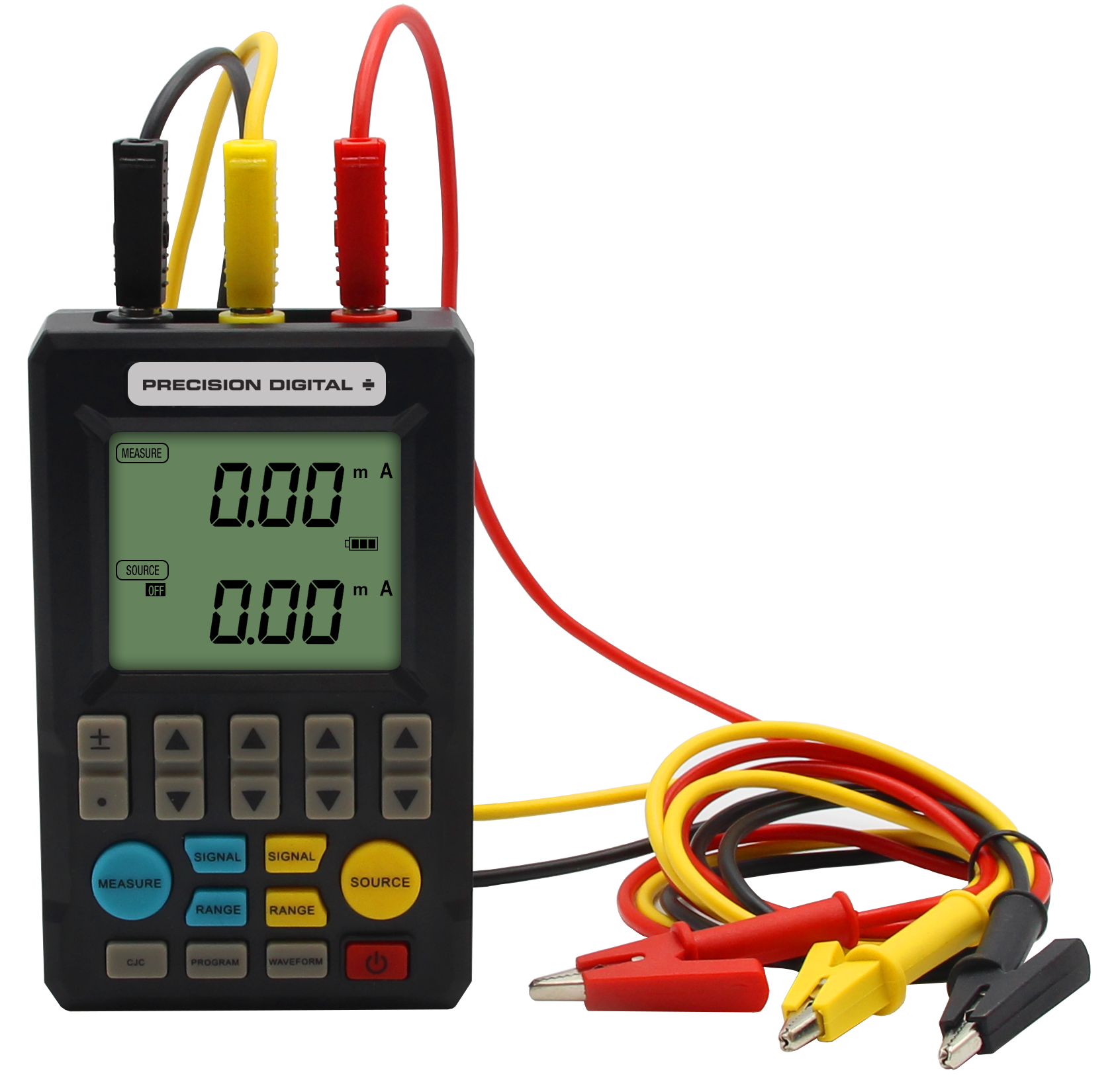
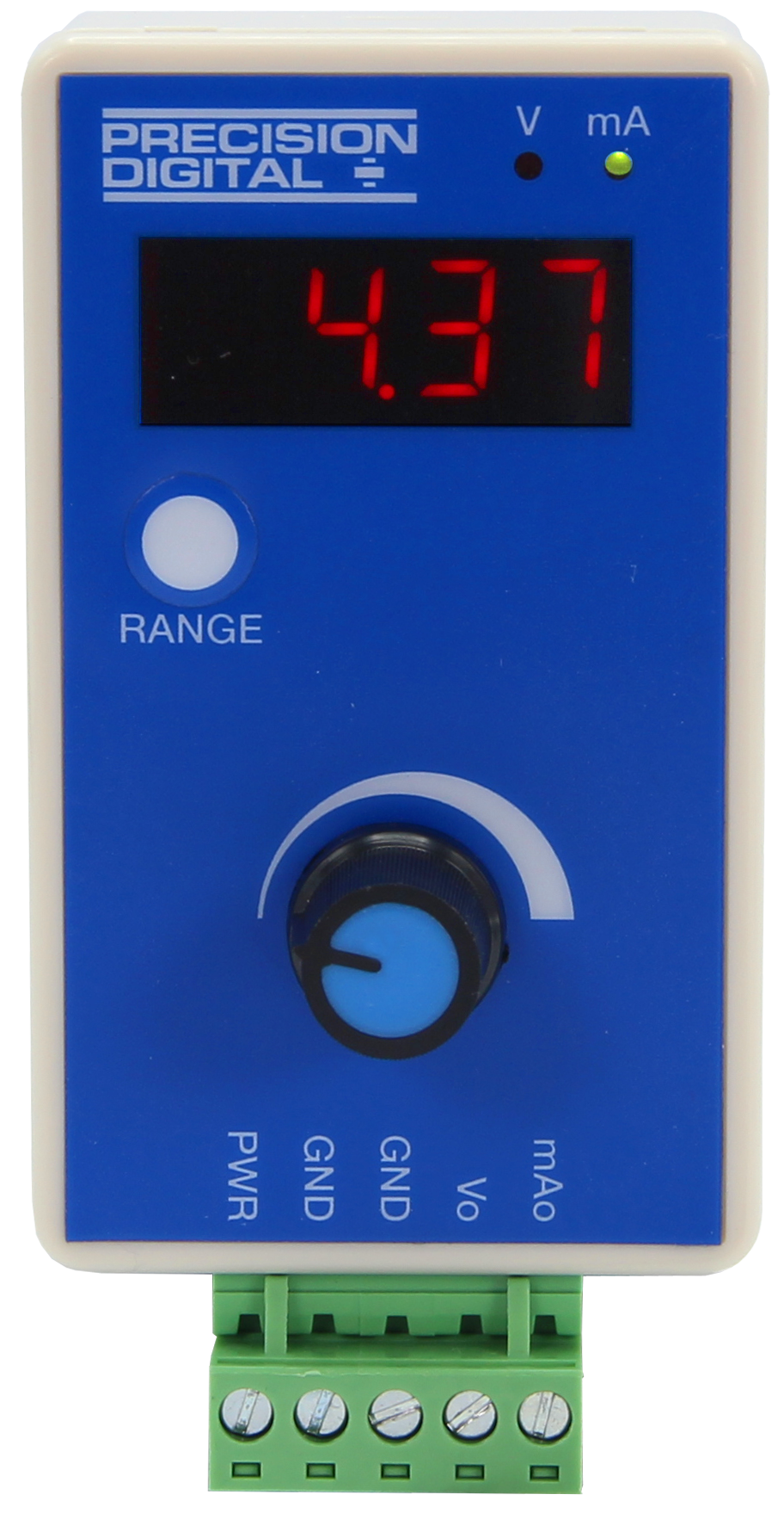
- Calibrators, Signal Isolators, Splitters, & Generators
- Control Stations
- Custom Enclosure Assembly
- Demo Units
- Digital Panel Meters
- Enclosures
- Explosion-Proof
- Field-Mount Indicators
- Industrial Wireless
- Intrinsically Safe
- Large Display
- Light/Horn
- Loop-Powered Meters
- Modbus Displays
- Modifications
- Multi-Channel Controllers
- Process Value Alarm Enclosure Assembly
- Sun Hoods
- Subpanel Wiring Assembly
- Temperature Controllers
- Level
- Level (Feet & Inches)
- Process
- Pressure
- Temperature
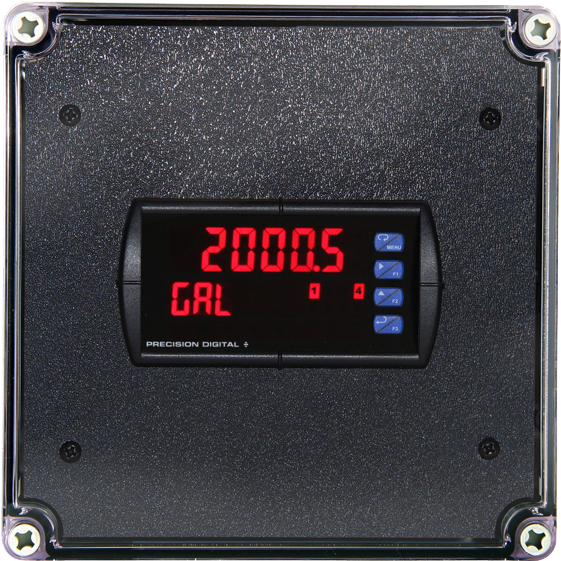
- Flow Rate/Totalizer
- Pump Control
- Chemical Bulk Storage
- Strain Gauge
- Load Cell
- Hazardous Area
- Industrial Wireless
- Batch Control
- PID Control
- Modbus
- Annunciator
- Calibration
- Data Logging
- Signal Conditioning
- Signal Generation
- Signal Isolating
- Signal Splitting
- High Current
- Speed
- Weight

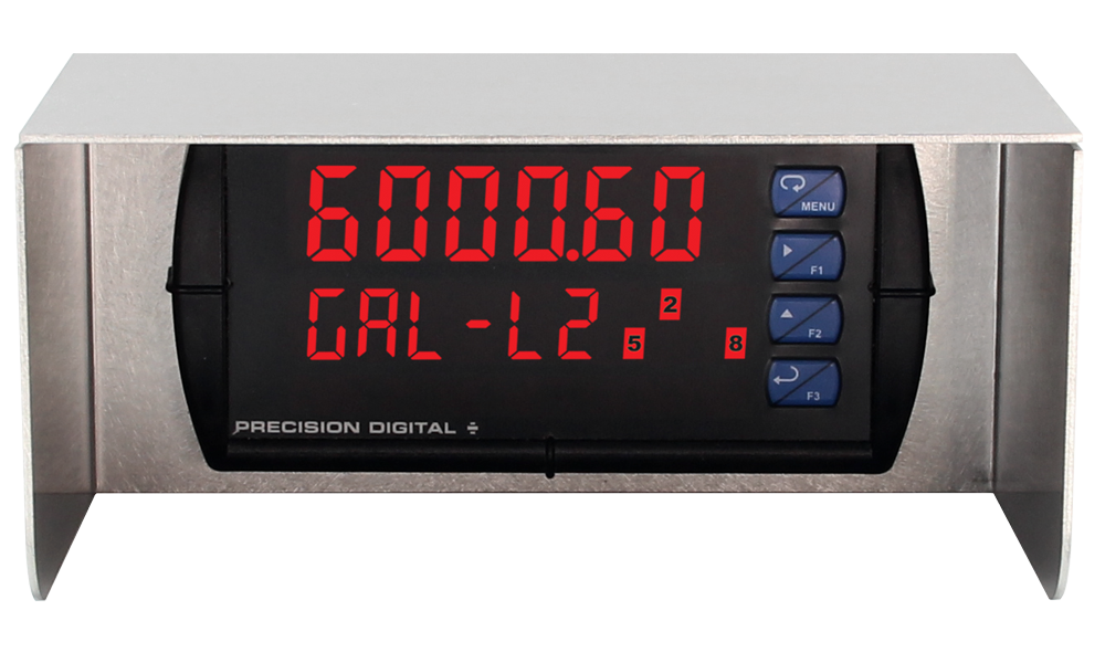
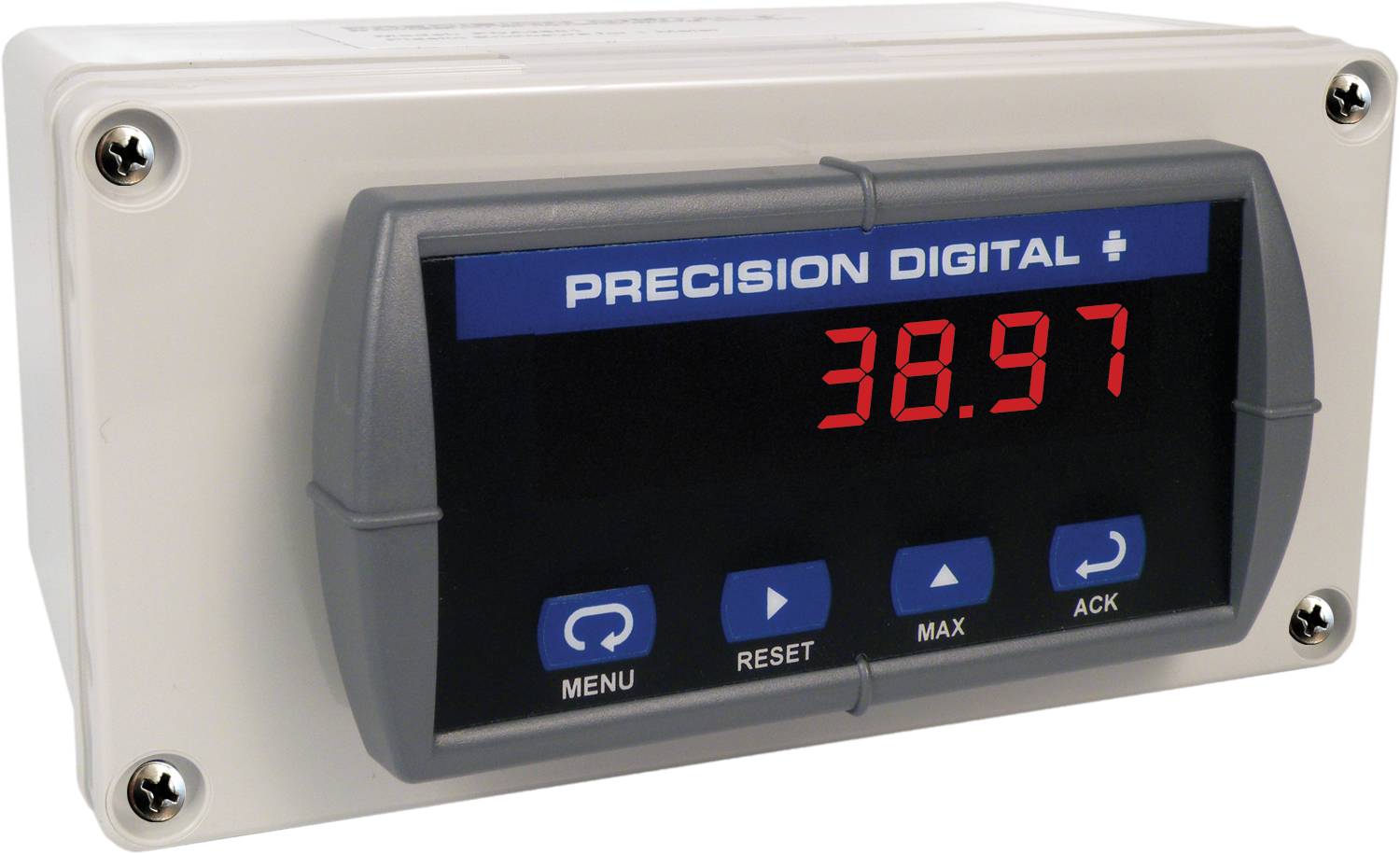
Trident Process & Temperature Digital Panel Meter

PD765 Left


Models in stock
from $303.00
The Trident PD765 is a 1/8 DIN digital panel meter for process and temp inputs with a bright display, NEMA 4X front, and optional relays and Modbus.
Why Should You Buy:
- Big Display
- 1/8 DIN Panel Meter
- Universal Inputs
- 2 Relays & 4-20 mA Output

The PD765 Trident digital panel meter is one of the most versatile digital panel meters on the market and will satisfy a wide variety of process and temperature applications. The Trident can be field programmed to accept process voltage (0-5V, 1-5V, etc) and current (4-20 mA) inputs, 100 Ohm RTDs, and the four most common thermocouples.
One of the Trident’s most useful features is its ability to provide 24 VDC to power the transmitter’s 4-20 mA signal. It is housed in a shallow-depth, 1/8 DIN enclosure that features a NEMA 4X front panel and convenient mounting hardware. There are two power options for the Trident: 85 to 265 VAC or 12-36 VDC and the AC powered version can provide 24 VDC to power the transmitter if needed. Programming and setup can be performed with the four front panel pushbuttons, free MeterView software or using the Copy function.
Two relays and isolated 4-20 mA output options increase the utility of the Trident meter. The relays can be used for alarm or control applications. The 4-20 mA output provides an isolated retransmission of the input signal; especially useful for temperature inputs like thermocouples and RTDs.
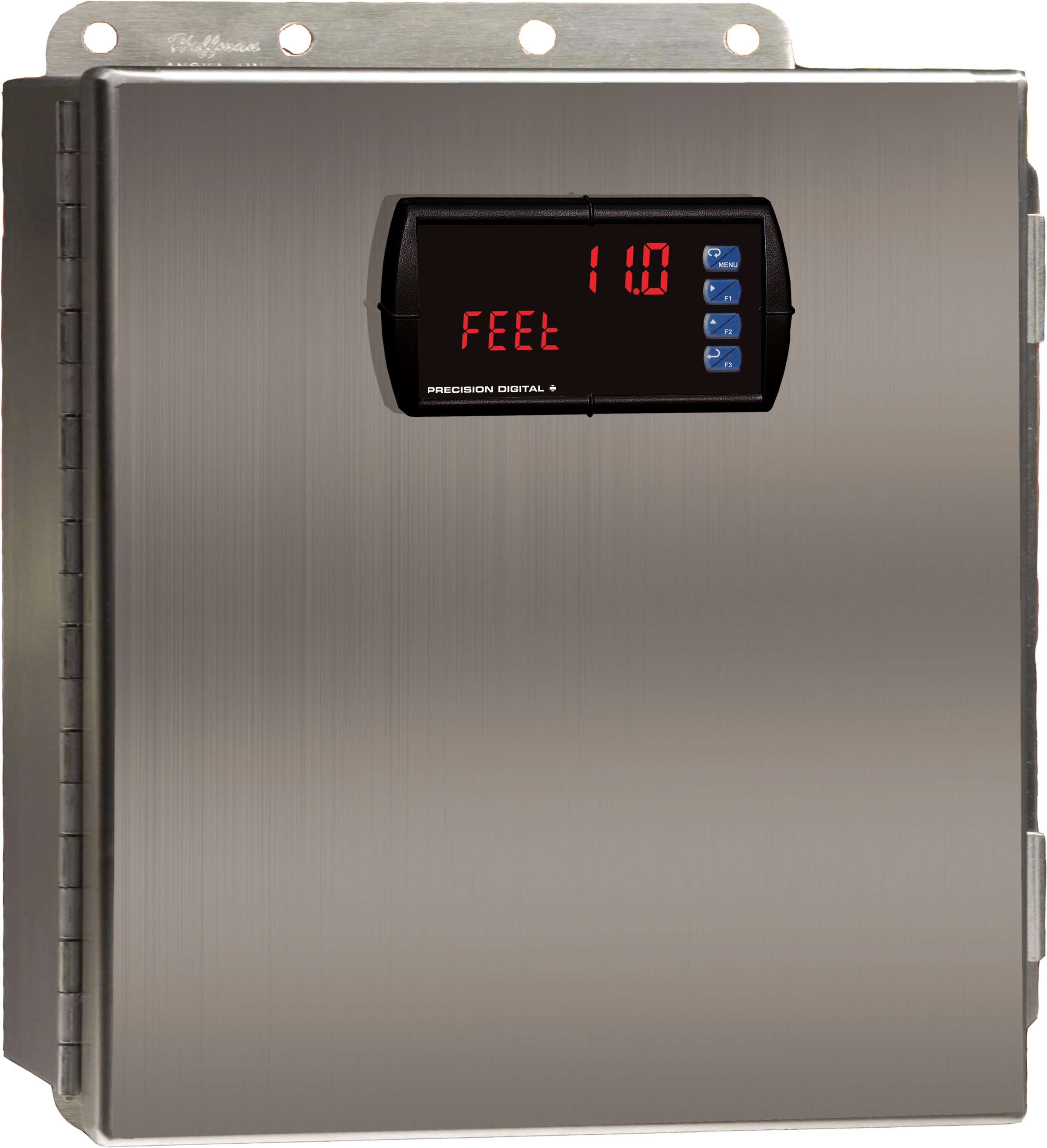
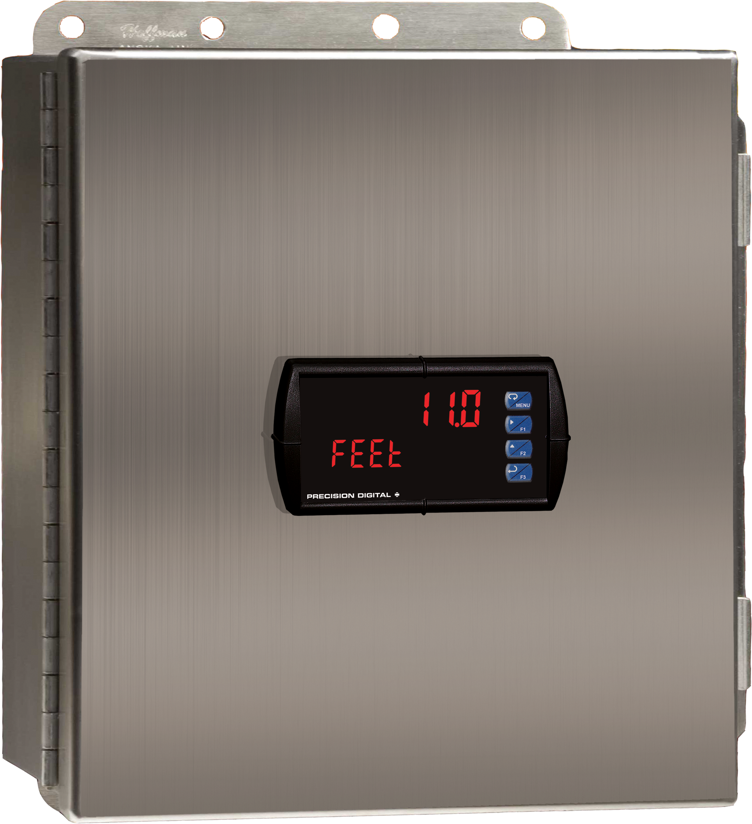
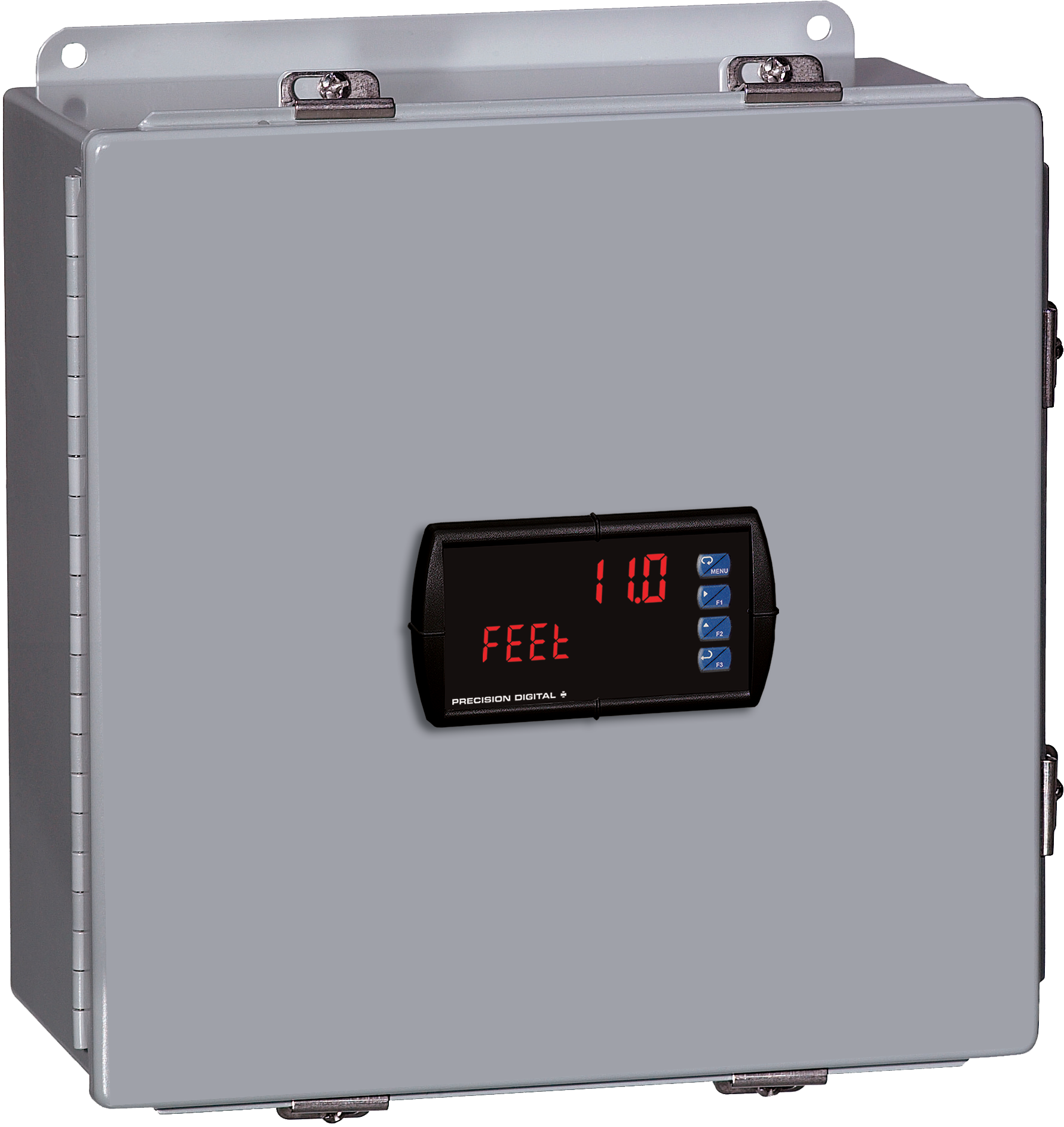
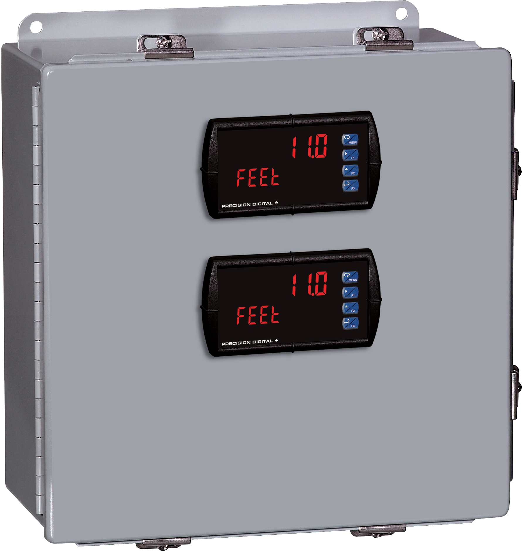
The display height on the standard Trident meter is 0.56" (14.2 mm) and on the Trident X2 the display height is an astounding 1.2" (30.5 mm). The Trident X2 can be read easily from distances of up to 30 feet!
The intensity of the display on both versions of the Trident can be adjusted to compensate for various lighting conditions, including direct sunlight.
Both meters are available with all Trident features, although only the Trident X2 includes four external button contacts.
Inches (mm)


×![Enlarged View]()
Documentation & Resources
Product Information (3)
Modbus Register Tables (2)
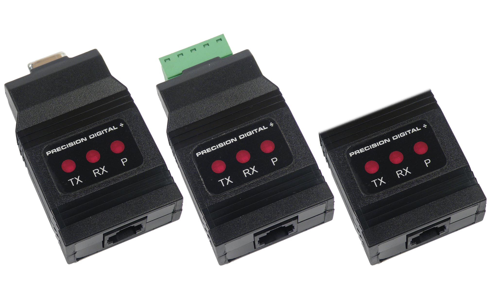
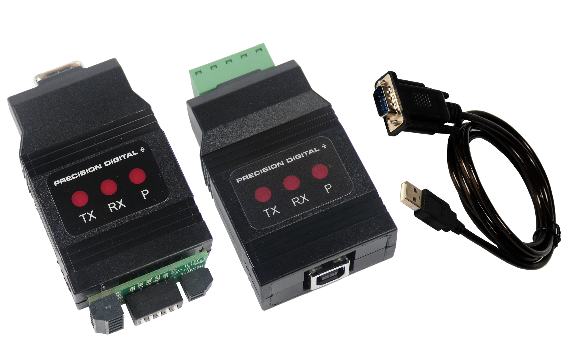
MeterView software allows all PD765 or PD8-765 setup parameters to be programmed from a PC and to save the configuration settings to a file for reporting or programming other meters. For programming purposes, MeterView software connects to the PD765 or PD8-765 meter via a PDA8006 USB serial adapter.
NOTE:
PD765 or PD8-765 meters are not powered from USB connection and require external power to be programmed.
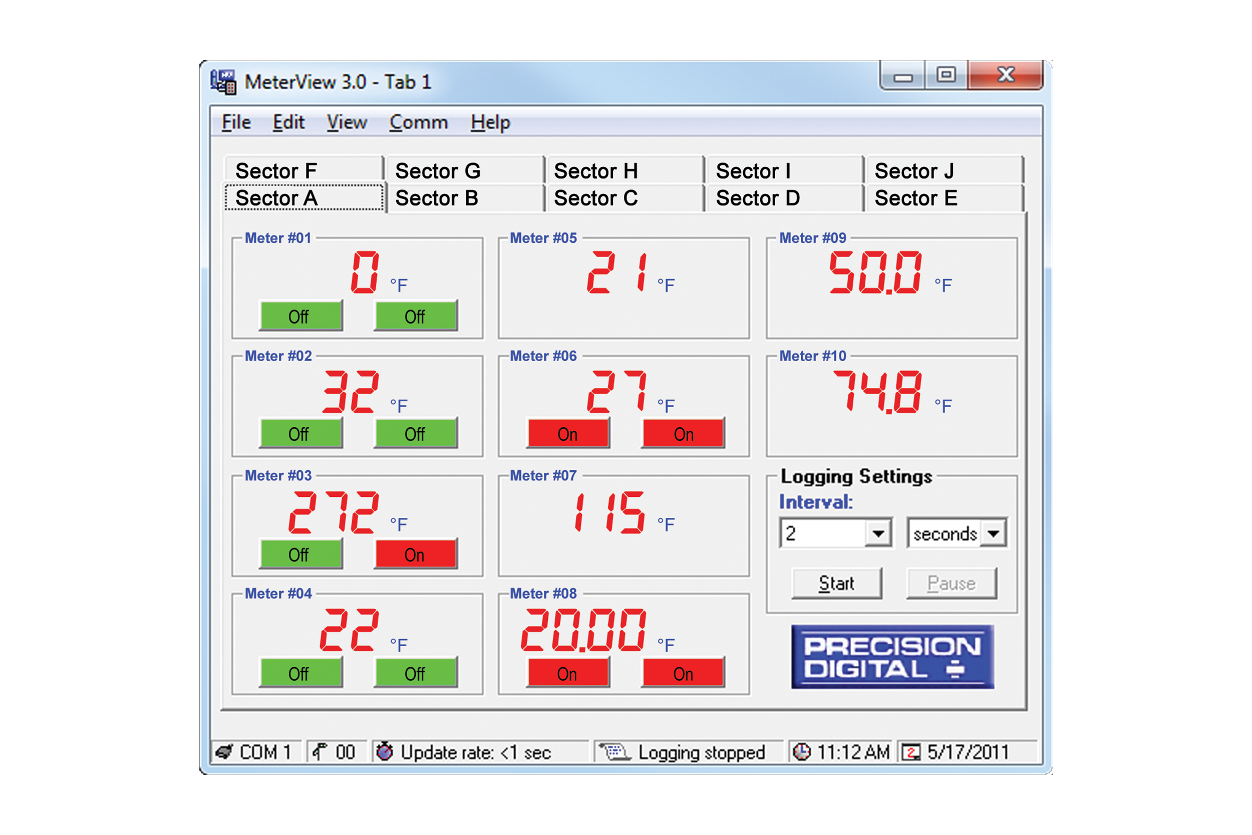
MeterView software can be installed on any Microsoft Windows 10/11 computer. Connect the meter to the computer using PDA8006 USB serial adapter (sold separately). The meter is powered via USB, so there is no need to wire anything before programming it. USB connection is intended for configuration purposes only.

General
System Requirements
Microsoft Windows 10/11
Availability
Communications
RS-232 adapter or RS-485 adapters with an RS-232 to RS-485 or USB to RS-485 converter may be used for communicating with the meters.
USB Adapter for Programming Only
For programming purposes, MeterView software connects to the PD765 or PD8-765 meter via the low-cost PDA8006 USB serial adapter.
Number of Meters
Up to 100 meters simultaneously with addressing capability; minimum scan time for 100 meters: 60 sec
Meter Address
00 to 99
Baud Rate
300 bps to 19,200 bps; selection must match the baud rate selected in the meters.
Screen Update Rate
Dependent on system and meter settings. Rates of up to 10 meters/second are attainable at 19,200 bps.
Configuration
Configure meter settings one meter at a time.
Configuration Report
Save configuration to PDC file format or export to HTML for printing, cloning, or restoring meter.
Logging Interval
2 seconds to 60 hours or manual
Manual Logging
Data saved to file when Log button is pressed.
Data Logging Report
Log data to HTML file format. All enabled meters are logged to a single file.
Alarm Notification
Pop-up message indicates new alarm condition. Alarm alert notification may be disabled.
Event Log
Important events are logged with date and time stamp.
Relay/Alarm Status
Indicate relay/alarm status with customized color and message label. Relay status indication may be disabled.
Units & Tag Number
Show engineering units and tag number information; these settings are not saved to the meter.
Relay Acknowledge
Relays may be acknowledged by clicking on corresponding Relay Status button. Meters must be set up for manual reset and Relay Mode must be enabled in MeterView.
Latest Version
3
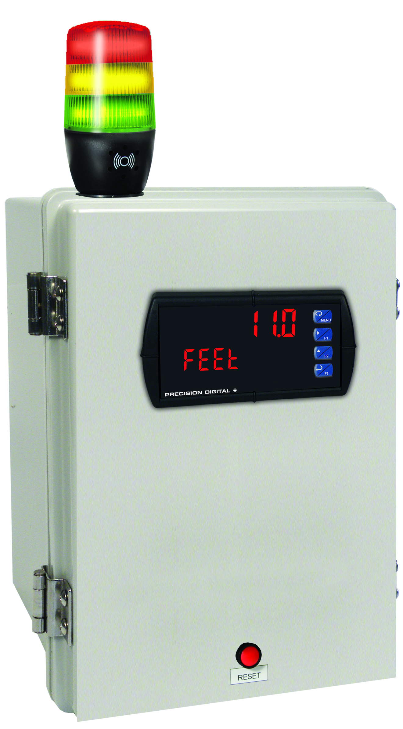
MOD-LH3LCB1-RYG
Modification: Three Color Light/Horn and Reset Button with Holes Drilled for Light/Horn and Reset Button in Enclosure. Enclosure & meter sold separately and assembly required by user.

MOD-LH5CB1
Modification: Five Color Light/Horn and Reset Button with Holes Drilled for Light/Horn and Reset Button in Enclosure. Enclosure & meter sold separately and assembly required by user.
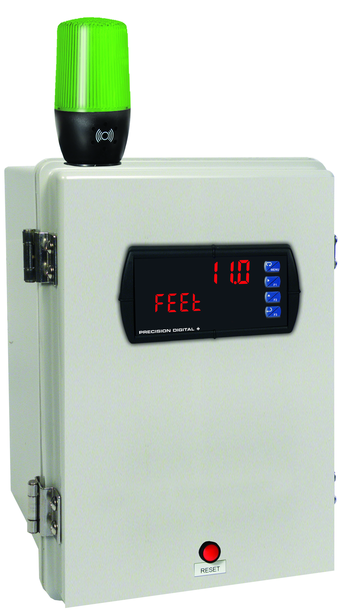
MOD-LHGB1
Modification: Green Light/Horn and Reset Button with Holes Drilled for Light/Horn and Reset Button in Enclosure. Enclosure & meter sold separately and assembly required by user.
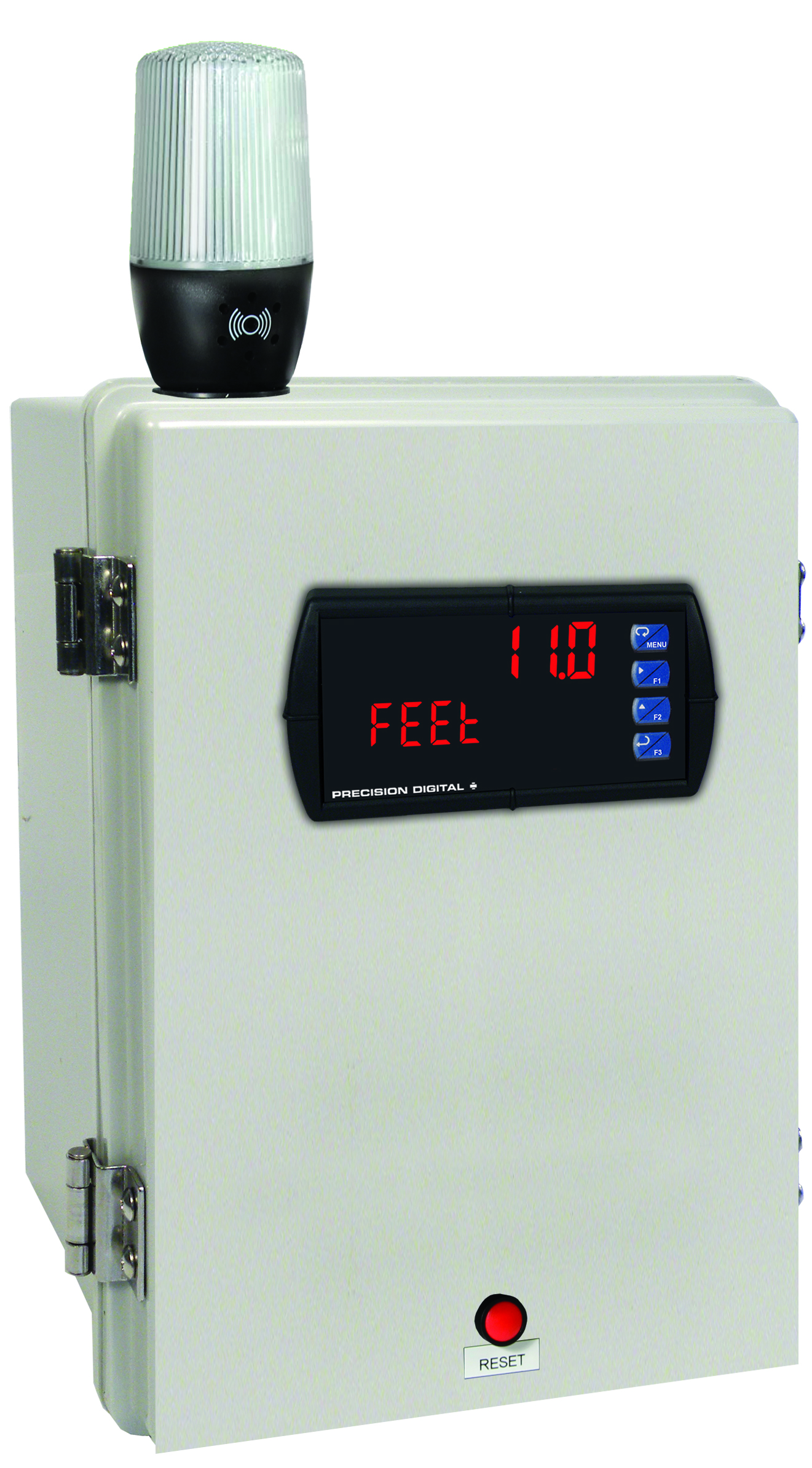
MOD-LHWB1
Modification: White Light/Horn and Reset Button with Holes Drilled for Light/Horn and Reset Button in Enclosure. Enclosure & meter sold separately and assembly required by user.
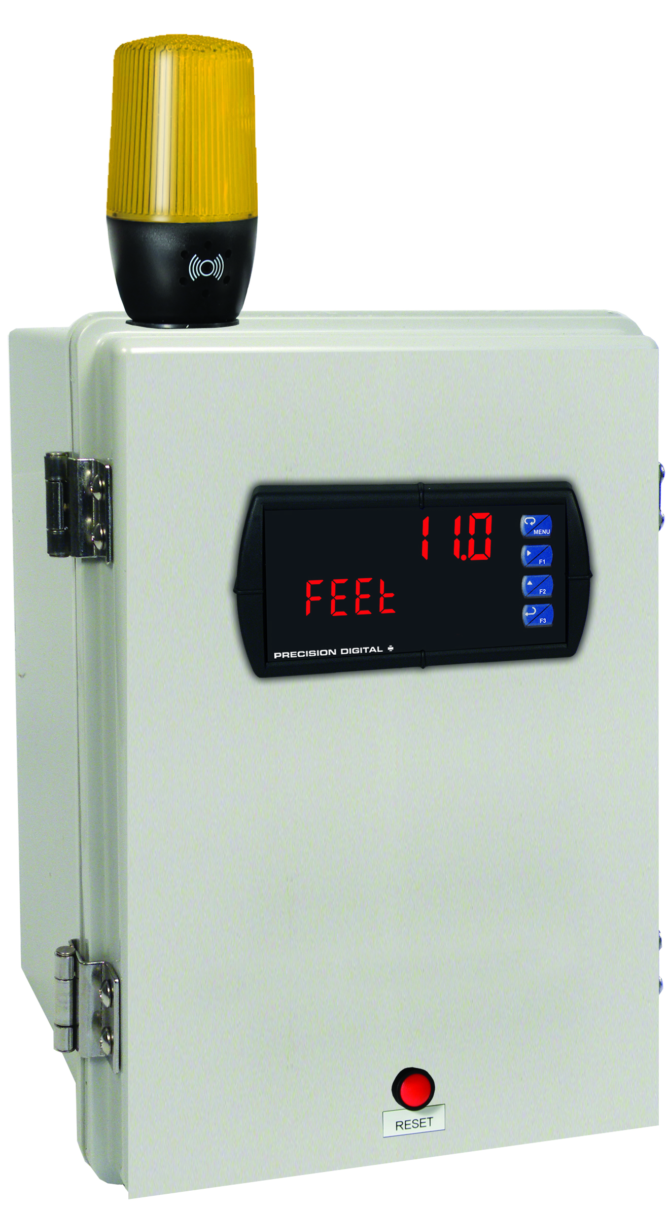
MOD-LHYB1
Modification: Yellow Light/Horn and Reset Button with Holes Drilled for Light/Horn and Reset Button in Enclosure. Enclosure & meter sold separately and assembly required by user.

PDA2322
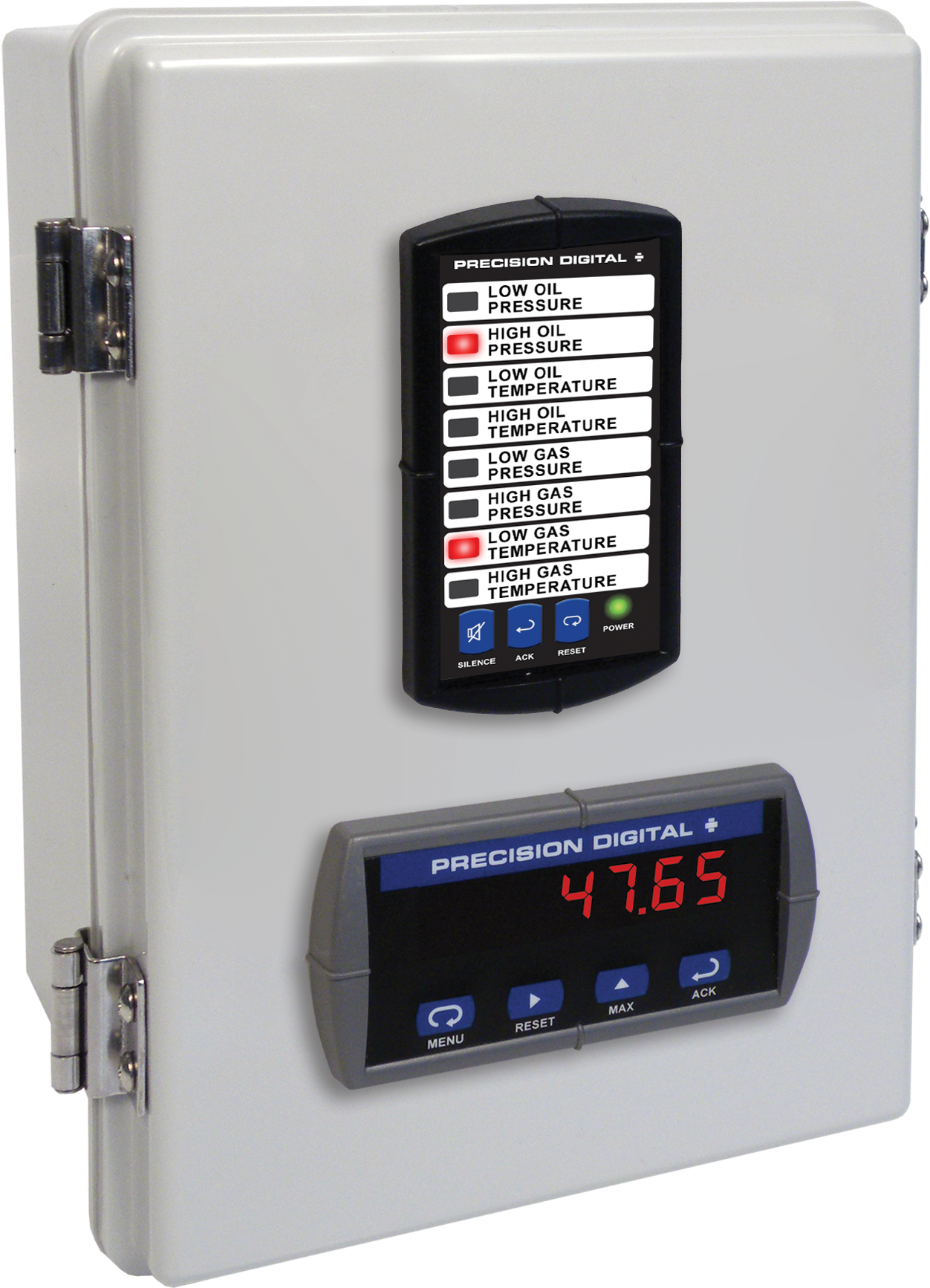
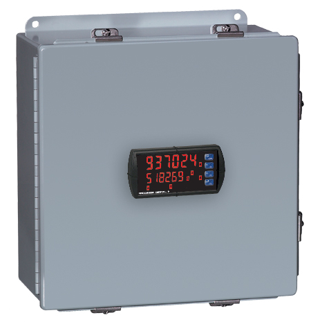
Plastic UL Type 4X Enclosure with (1) Vertical and (1) Horizontal 1/8 DIN Cutouts

PDA2604-1C
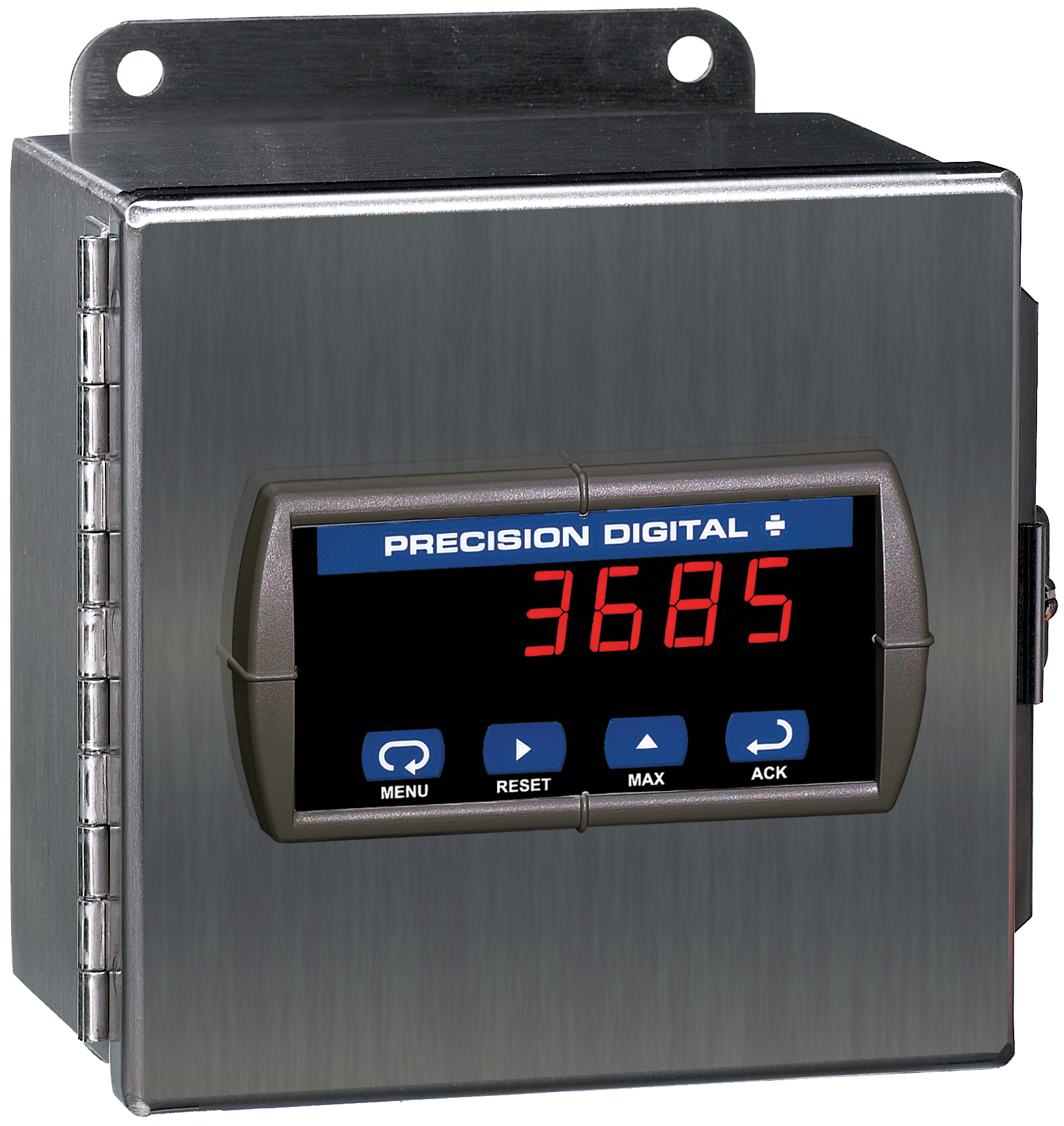
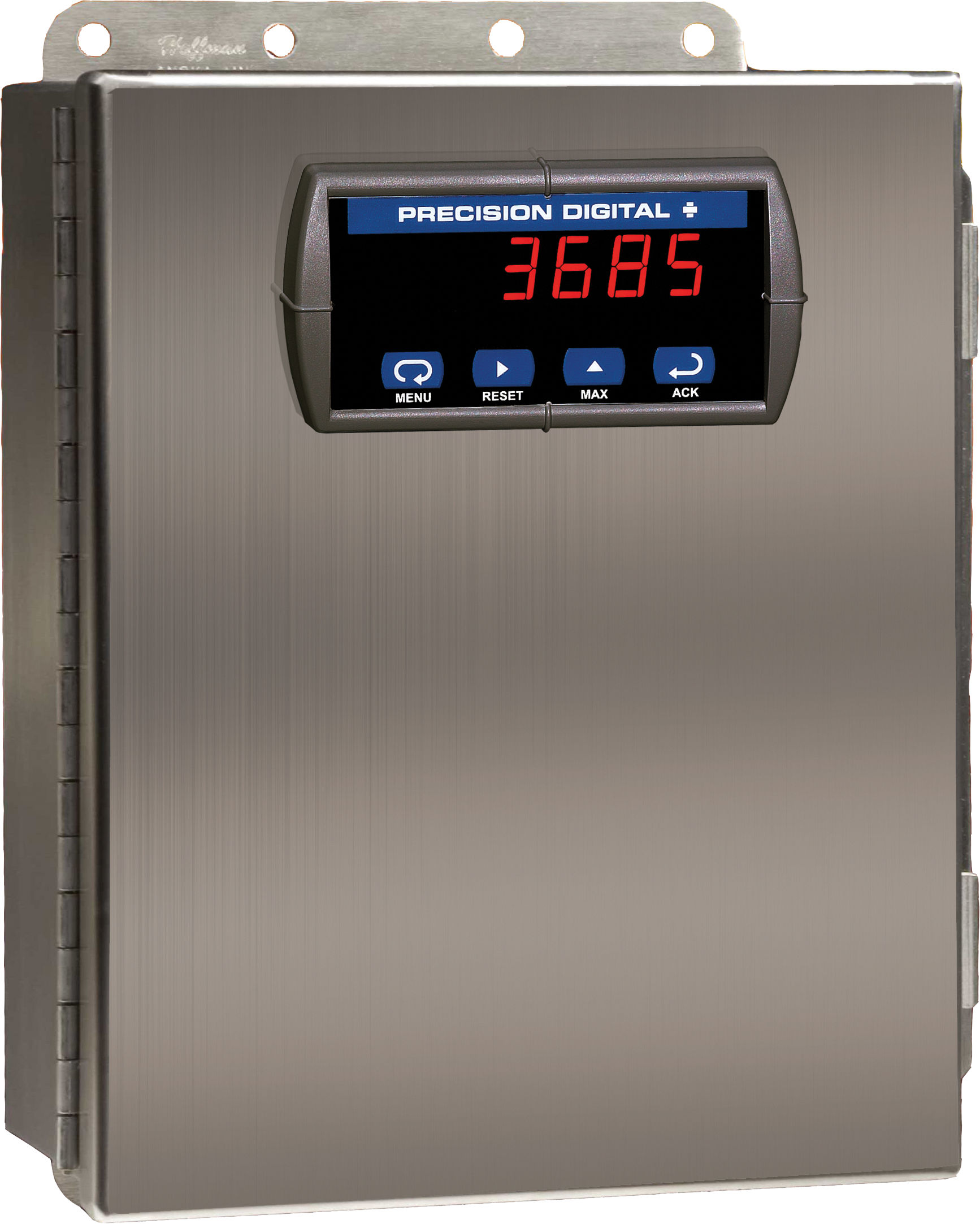
Stainless Steel UL Type 4X Enclosure with (1) Centered Horizontal 1/8 DIN Cutout
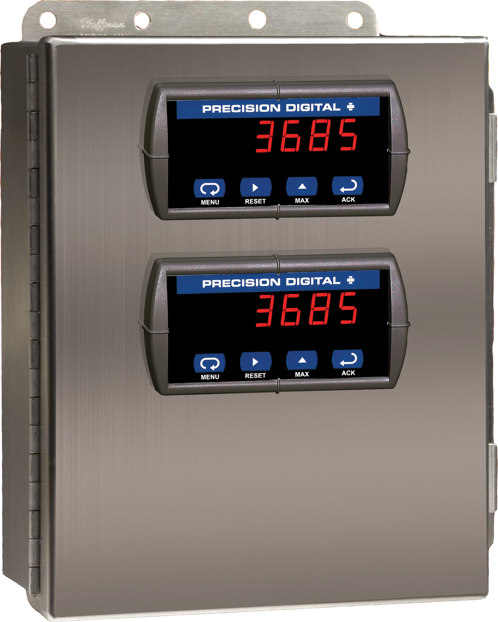
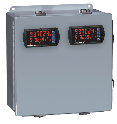
PDA2604-2C
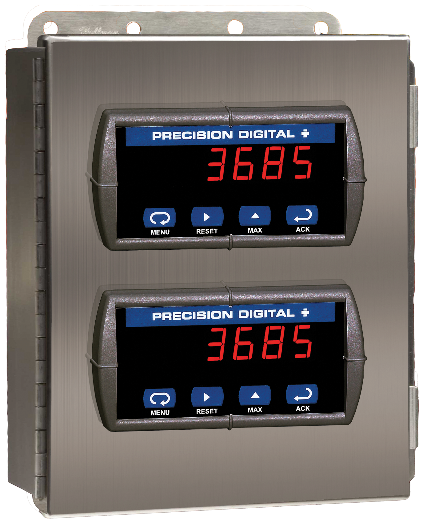
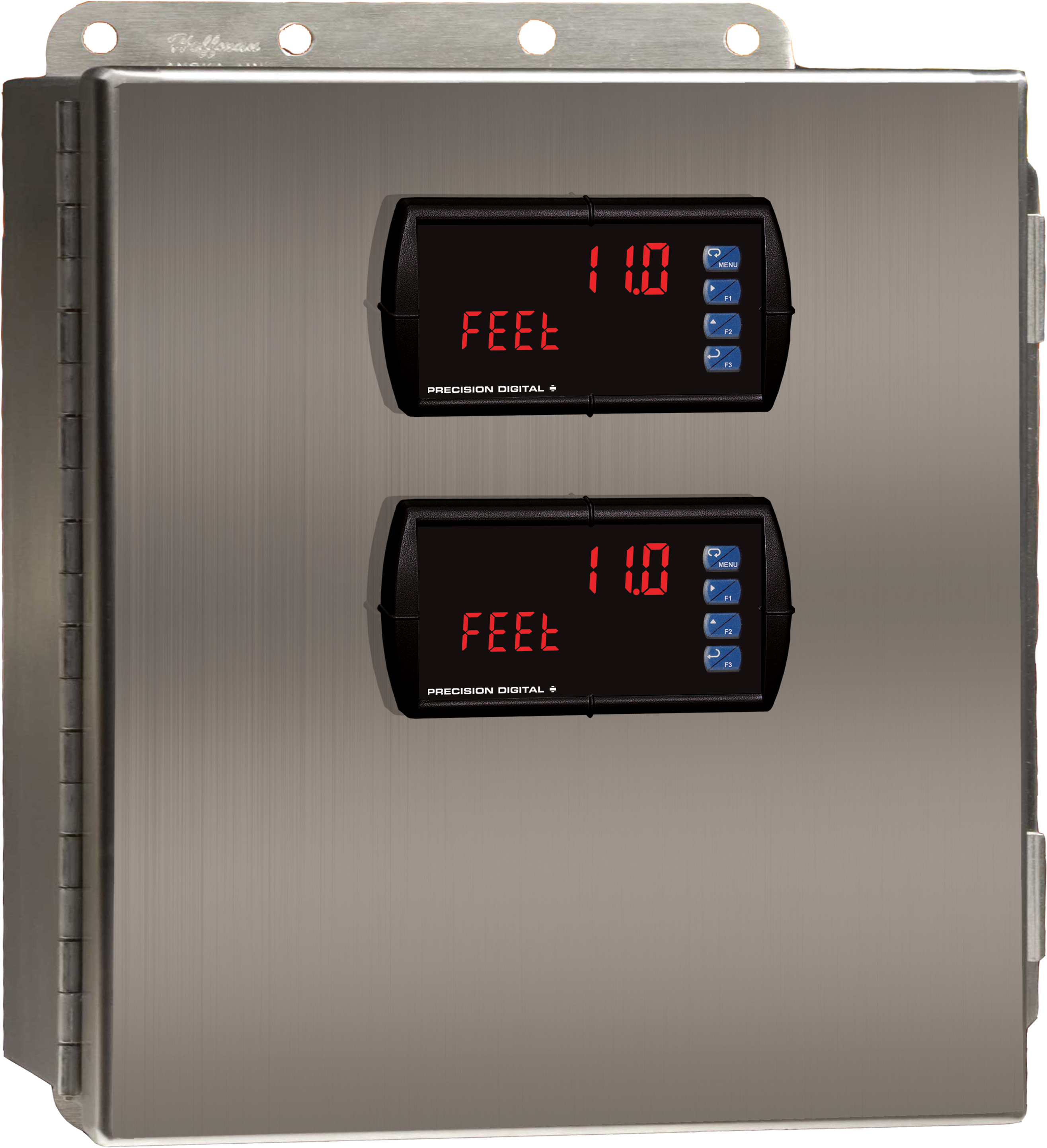
Stainless Steel UL Type 4X Enclosure with (2) Centered Horizontal 1/8 DIN Cutouts
PDA2604-3C
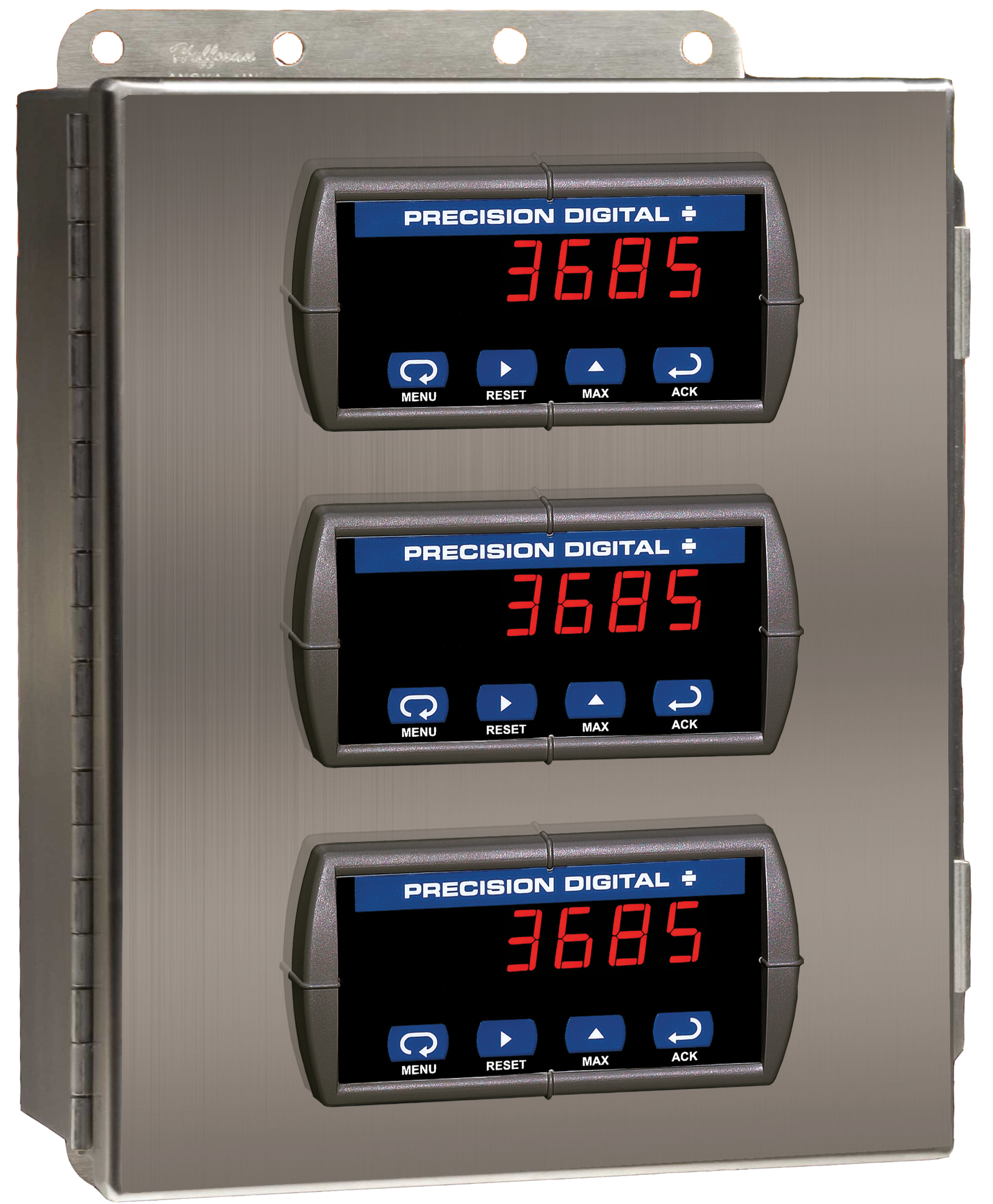
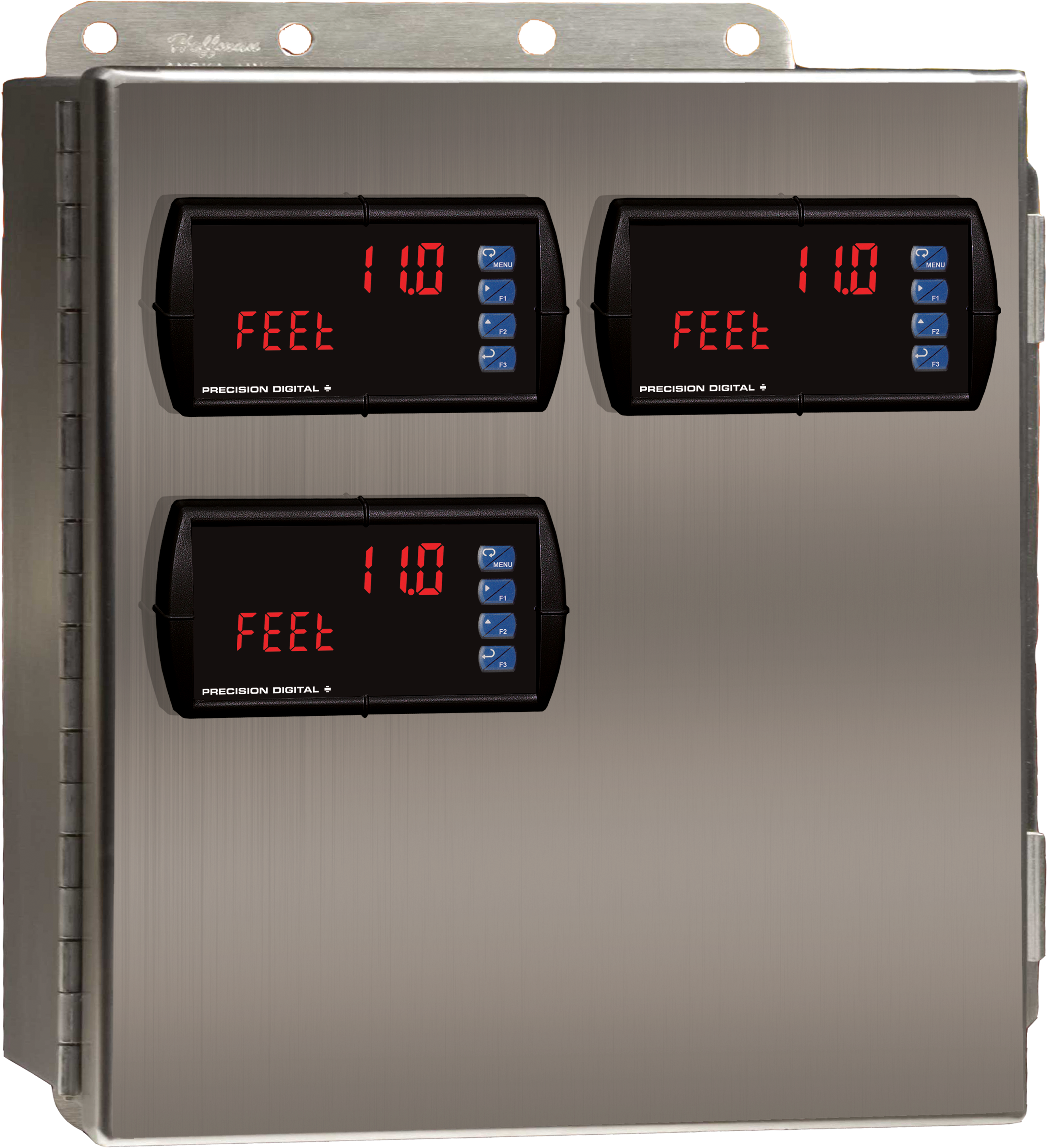
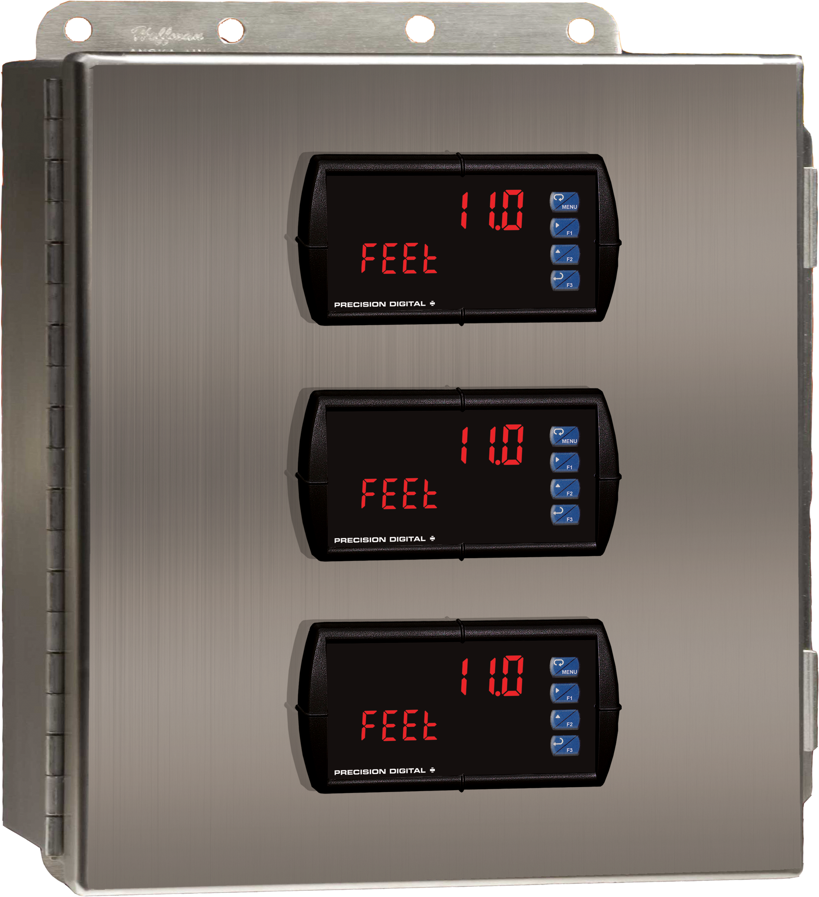
Stainless Steel UL Type 4X Enclosure with (3) Centered Horizontal 1/8 DIN Cutouts

PDA2622
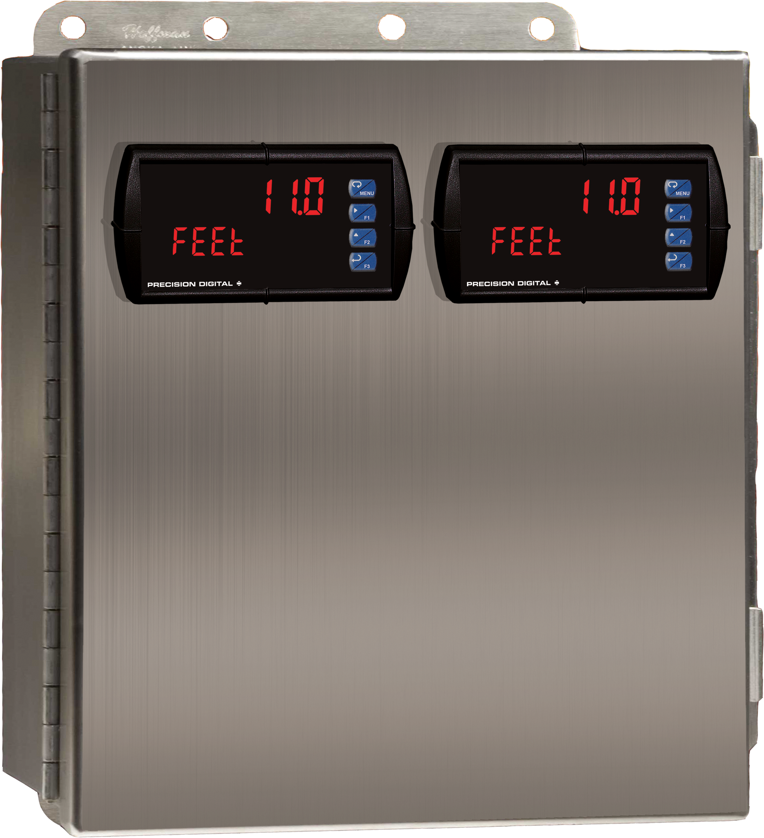
Stainless Steel UL Type 4X Enclosure with (1) Vertical and (1) Horizontal 1/8 DIN Cutouts


PDA2821
Plastic UL Type 4X Enclosure with (1) Vertical and (1) Horizontal 1/8 DIN Cutouts
PDA3414
Plastic UL Type 4X Enclosure with (1) Vertical and (1) Horizontal 1/8 DIN Cutouts