Quick & Easy Scale & Programming Methods
The ProVu can be programmed either via the front panel push buttons or free, PC-based MeterView Pro software. MeterView Pro is resident on the ProVu and is accessed by a provided USB cable, so it is by far the easiest way to program the ProVu. The ProVu can be calibrated either by applying a known signal or scaled by entering a desired value with the front panel buttons or MeterView Pro software. Most customers will use the scaling method because it is simpler and does not require a calibrated signal source. Selecting the input to be current or voltage is done with the front panel buttons or MeterView Pro software. Once programming is completed it can be locked with a password.
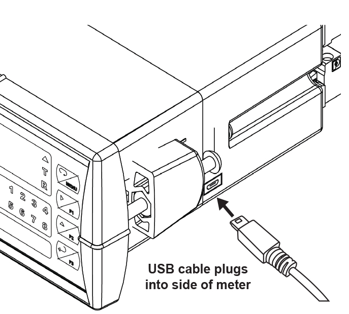
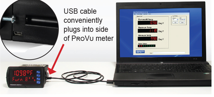
Free PC-Based MeterView Pro USB Programming Software & Cable
The ProVu comes preloaded with free MeterView Pro programming software that connects and installs directly to your PC with a standard USB cable, also provided free with each instrument. This eliminates the need to insert CDs, install drivers, or download software from the internet. When you connect your ProVu to your PC, MeterView Pro is downloaded to your PC, the software automatically selects the model you are programming, and you’re ready to start programming immediately. Further simplifying the programming process, the ProVu can be powered from the USB port, so no need to apply external power while programming your meter. In addition to programming, the software will also allow you to monitor, and datalog a ProVu using your PC. You can also generate and save programming files for later use.

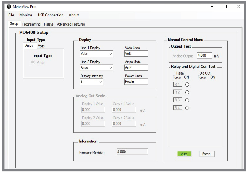
Setup Screen
- Select Voltage or Current Input
- Select Decimal Point
- Set Line 1 Display Parameters
- Set Line 2 Display Parameters
- Set Analog Output Values
- Enable Manual Control
- Test Relays & Digital Outputs
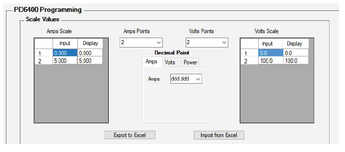
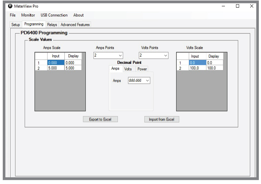
Programming Screen
- Set Scale Values
- Set the Number of Points (up to 32)
- Import from Excel
- Export to Excel
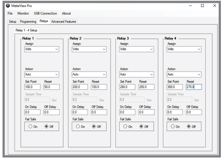
Relays Screen
- Greatly Simplifies Programming a Variety of Relay Features
- Set Relay Action
- Set Sampling Time
- Set Set & Reset Points
- Set On/Off Time Delays
- Set Fail-Safe Operation
- Set Input Break Relay Action
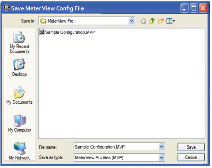
Save/Open Configuration
At the bottom of most MeterView screens are two tabs:
- Get Meter Data: This reads the programming of the meter that is currently connected to the PC.
- Send Meter Data: Clicking this button, sends current MeterView programming to the meter.

The configuration file can be sent, or retrieved, from the directory of your choice. This makes it very easy to program multiple meters with the same programming. It is also a great backup utility as well.
Specifications
System Requirements:
Microsoft® Windows® XP/Vista/7/8/10
Communications:
Onboard USB (firmware version 4.0 or higher),
RS-232 Adapter, or RS-485 Adapter
Meter Address: 1 - 247
Reports:
- Data logging: Save as CSV file format
- Configuration: Save as PDC file format or print configuration
Baud Rate: 300 - 19,200 bps
Configuration: One meter at a time
Protocol:Modbus RTU (requires Helios firmware version 4.0 or higher)
*Note: Windows® 32/64-bit operating systems
Password Protection
The Password menu is used for programming three levels of security to prevent unauthorized changes to the programmed parameter settings:
Pass 1: Allows use of function keys and digital inputs
Pass 2: Allows use of function keys, digital inputs and editing set/reset points
Pass 3: Restricts all programming, function keys, and digital inputs
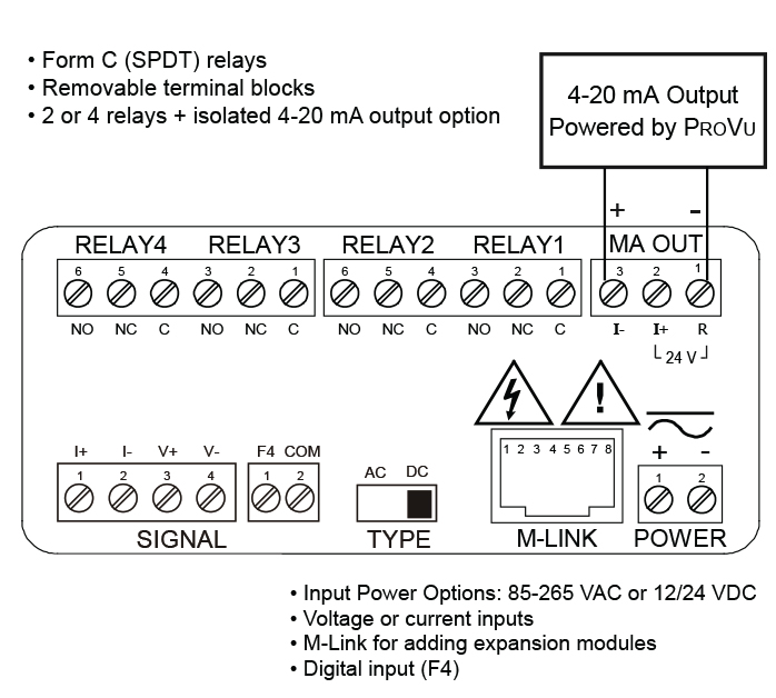
4-20 mA Output & Relays
4-20 mA Analog Output
The isolated analog output can be configured to represent the process variable (PV), maximum (peak) value, minimum (valley) value, the value for any of the eight relay set points, or Modbus input. While the output is nominally 4-20 mA, the signal will accurately accommodate under- and over-ranges from 1 to 23 mA.
The 4-20 mA output can be reversed scaled such that 4 mA represents the high value and 20 mA represents the low value. For instance, a 4-20 mA output signal could be generated as the meter went from 100.0 to 0.0.
For applications where the input was linearized by the ProVu, the 4-20 mA output will represent that linearized value.
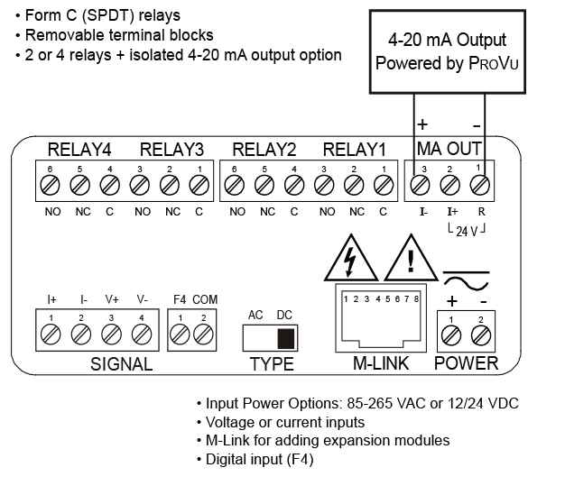
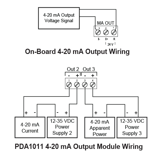
Connections
The ProVu can provide 40 mA at 24 VDC to power the 4-20 mA output signal or an external power supply can be used:
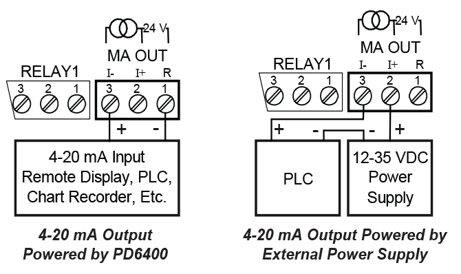
The internal 24 VDC power supply powering the analog output may be used to power other devices, if the analog output is not used. The I+ terminal is the +24 V and the R terminal is the return.
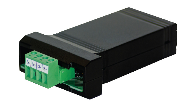
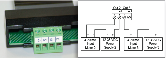
PDA1011 Dual Isolated 4-20 mA Output Module
In addition to the on-board 4-20 mA output option, the PD6400 is also available with an external module that provides two more isolated 4-20 mA outputs. This allows the user to have separate 4-20 mA outputs for current, voltage and apparent power.
The 4-20 mA output can either be programmed using the front panel push buttons or free MeterView Pro software.
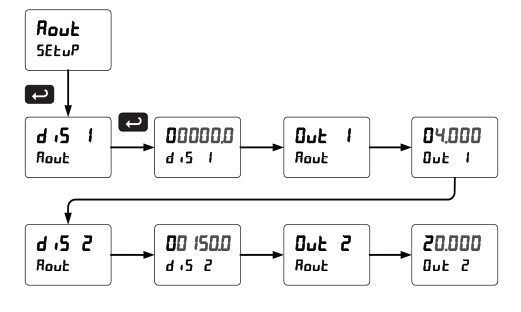
Front Panel Push Button Programming
The 4-20 mA analog output can be scaled to provide a 4-20 mA signal for any display range selected. No equipment is needed to scale the analog output; simply program the display values to the corresponding mA output signal. The Analog Output menu is used to program the 4-20 mA output based on display values.
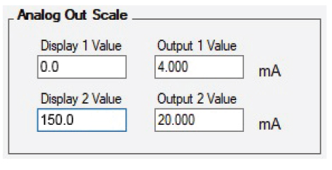
MeterView Pro Software Programming
When a meter is programmed as shown below, the output will be 4.00 mA when the display reads 0 and the output will be 20.00 mA when the display reads 150.0.
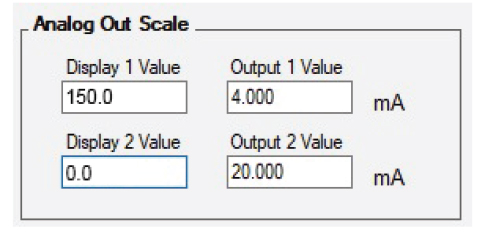
The meter can be set up for reverse scaling as shown below: the output will be 4.00 mA when the display reads 150.0 and the output will be 20.00 mA when the display reads 0.
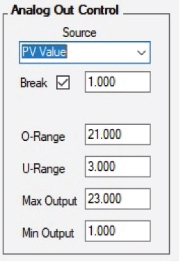
Source: Source for generating the 4-20 mA output (e.g. PV)
Overrange: Analog output value with display in overrange condition
Underrange: Analog output value with display in underrange condition
Break: Analog output value when current input break is detected
Max: Maximum analog output value allowed regardless of input
Min: Minimum analog output value allowed regardless of input
Relays for Alarm & Control Applications
Adding relays to the ProVu meter turns it into a sophisticated alarm device as well as a powerful, yet simple, alternative to a more complicated PLC system for control applications. The ProVu can be equipped with up to four 3 A Form C (SPDT) internal relays and an additional four more 3 A Form A (SPST) external relays. Relays are highly user-configurable as the following screen shot from MeterView Pro indicates:
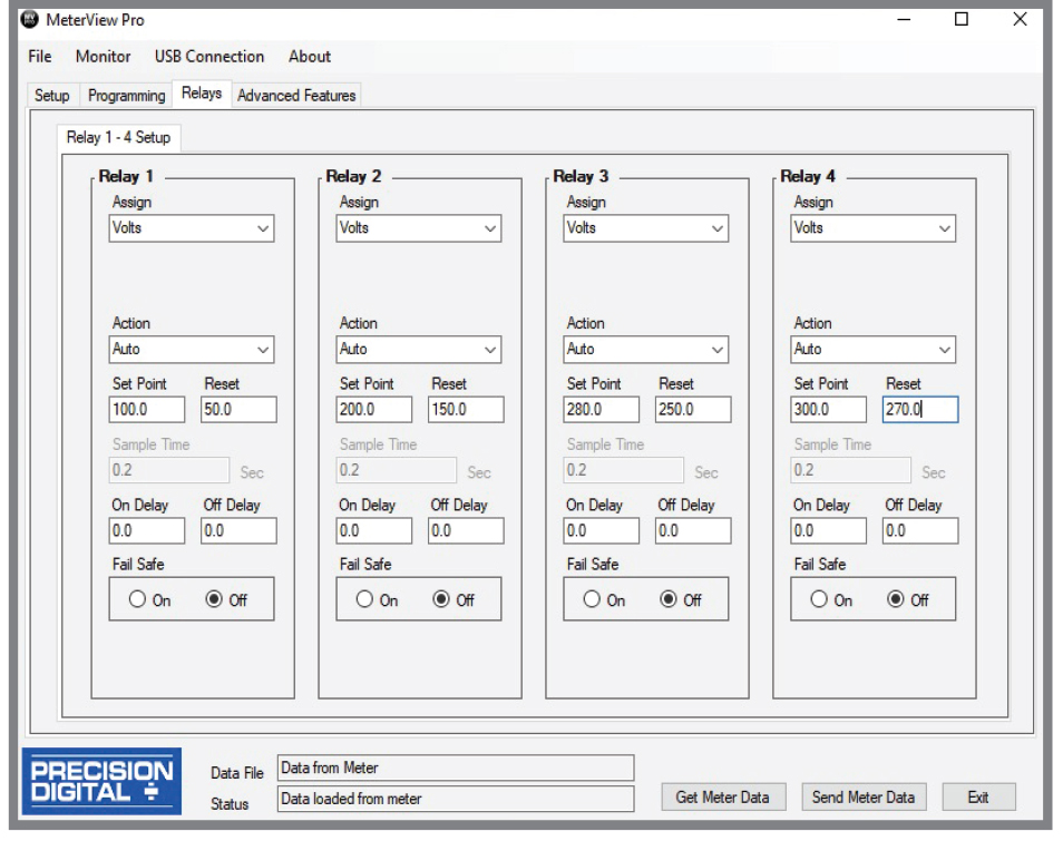
Setting Set and Reset Points (HI / LO Alarms)
All relays are independent of each other and may be programmed as high or low alarms with user desired set and reset points. Setting a set point above a reset point results in a high alarm and setting a set point below a reset point results in a low alarm. Alarms have 0 – 100% deadband and set and reset points may be set anywhere in the range of the meter.
Resetting the Relays (Action in MV Pro)
All relays are independent of each other and may be programmed to reset (Action in MV Pro) in the following ways:
- Automatic: Alarm will reset automatically once the alarm condition has cleared.
- Automatic/Manual: Alarm will reset automatically once the alarm condition has cleared but can also be reset using the F3 front panel button* at any time.
- Latching: Alarm must be reset manually and can be done so at any time. Press the F3 front panel button* at any time to clear the alarm.
- Latching with Reset after Cleared: Alarm must be reset manually and can only be done so after the alarm condition has cleared. Press the F3 front panel button* after the alarm condition has cleared to reset the alarm.
* Or by connecting an external switch to F4 terminal or with an optional digital input.
Time Delay (On and Off)
In many applications it is desirable to wait before turning off or on a relay – such as waiting for a process to settle before taking action. Each relay on the ProVu can be programmed with independent on and off time delays of 0 to 999.9 seconds to achieve this.
Relays Auto Initialization
When power is applied to the meter, the front panel LEDs and alarm relays will reflect the state of the input to the meter.
Signal Loss or Loop Break Relay Operation
When the meter detects a break in the 4-20 mA loop, the relay will go to one of the following selected actions:
- Turn On (Go to alarm condition)
- Turn Off (Go to non-alarm condition)
- Ignore (Processed as a low signal condition)
User Selectable Fail-Safe Operation
All relays are independent of each other and may be programmed for user selectable fail-safe operation. With the fail-safe feature activated, the relays will transfer to the alarm state on power loss to the meter.
Front Panel LEDs
The meter is supplied with four alarm points that include front panel LEDs to indicate alarm conditions. This standard feature is particularly useful for alarm applications that require visual-only indication.
Manual Output Control
Take control of any output with this feature. All relays can be forced ON or OFF, and the 4-20 mA output signal can be set to any value within its range. When the relays and 4-20 mA output are controlled manually, an LED labeled “M” is turned on and the associated Alarm LEDs (1-8) flash every 10 seconds indicating that the meter is in manual control mode.
Sampling Function (PV Triggered Timed Relay)
The sampling function allows the operator to set a relay as a “sampling” relay. When the PV reaches that set point, it will close that relay’s contacts for a preset period of time (0.1 to 5999.9 seconds).
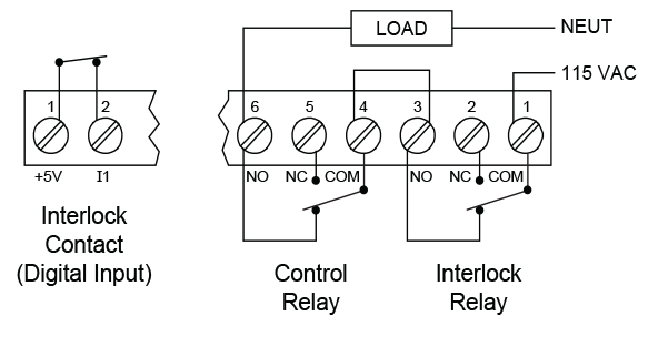
Interlock Relay(s)
This function allows a process to use one or more very low voltage input signals or simple switch contacts to control the state of one or more internal “interlock” relays. A violation (i.e. loss of input, open switch, or open circuit) forces one or more N/O interlock relay contacts to open. One input can be used in series with a number of interlock switches, or up to eight inputs can be required to force-on one (or more) internal interlock relays. Requires PDA1044 Digital I/O module or use of on-board digital input F4. Please see ProVu Series Safety Interlock Feature whitepaper on our website for more information.
Switching Inductive Loads
The use of suppressors (snubbers) is strongly recommended when switching inductive loads to prevent disrupting the microprocessor’s operation. The suppressors also prolong the life of the relay contacts. Precision Digital offers the PDX6901:
Application Examples
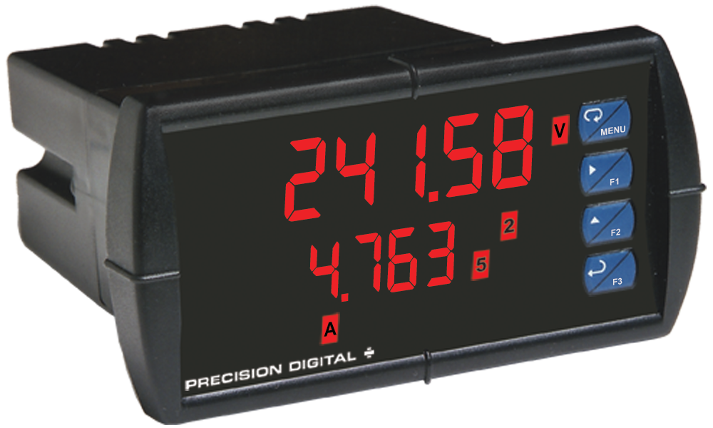
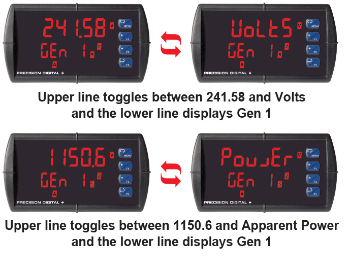
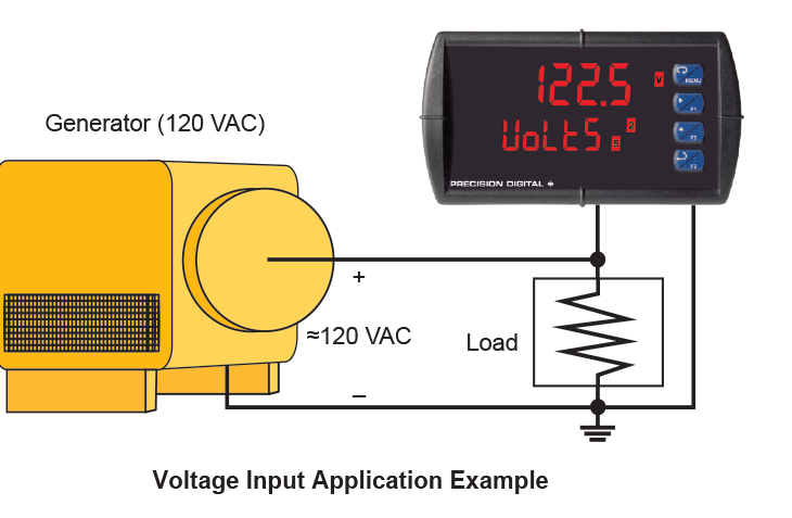
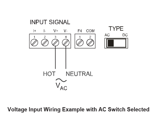
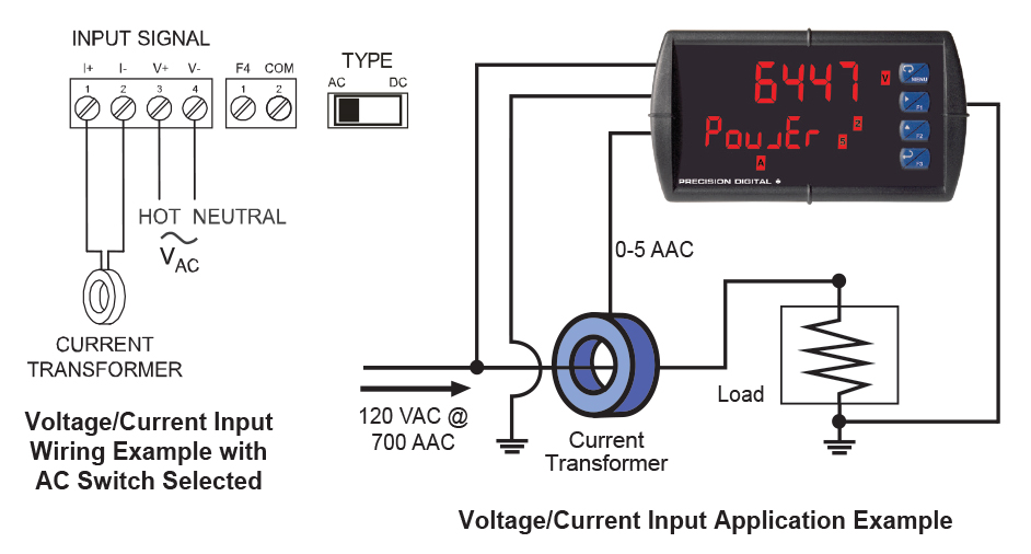
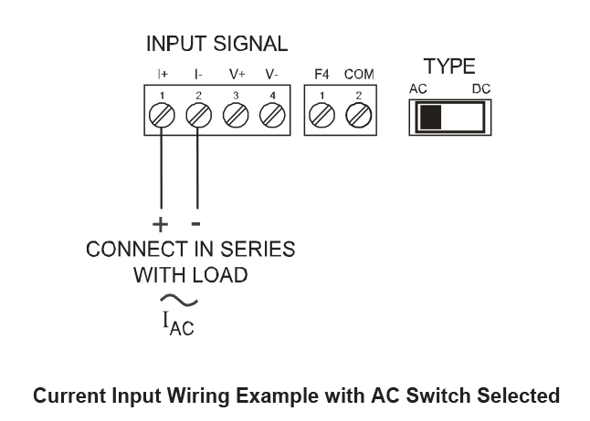
The PD6400 ProVu can be used to display application data for voltage, current, both, or apparent power. Each Channel, Voltage, or Current, can be scaled independently. The following examples show just a few of the PD6400's application capabilities using generators and transformers. Each example is followed by a wiring diagram that shows proper switch position for the meter.
Voltage Measurement for a Generator Driving a Load
Apparent Power Measurement with Three 4-20 mA Outputs
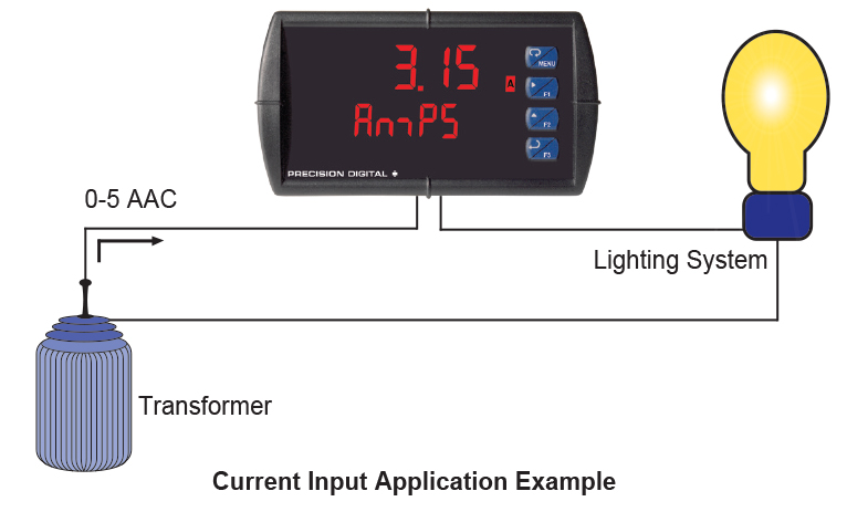
Current Measurement for a Lighting System
Converting High AC Current with the PDA6405 Split Core AC Current Transformer
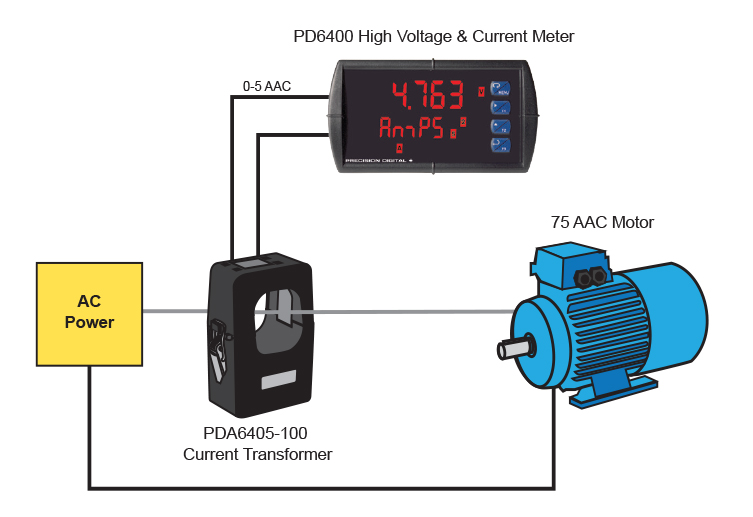
Measuring Current with PDA6405-100 Current Transformer and PD6400 digital panel meter
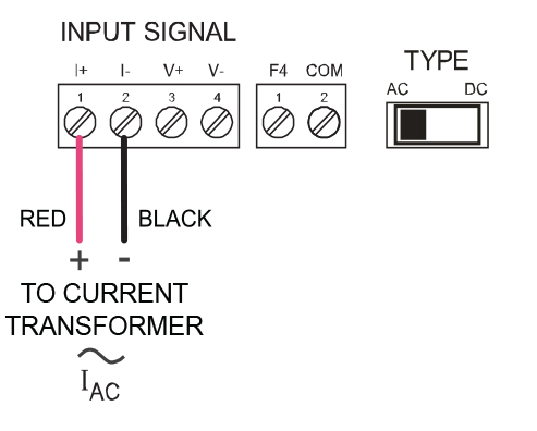
PD6400 Connections from PDA6405 Current Transformer with AC Switch Selected
PDA6405 Split Core AC Current Transformers
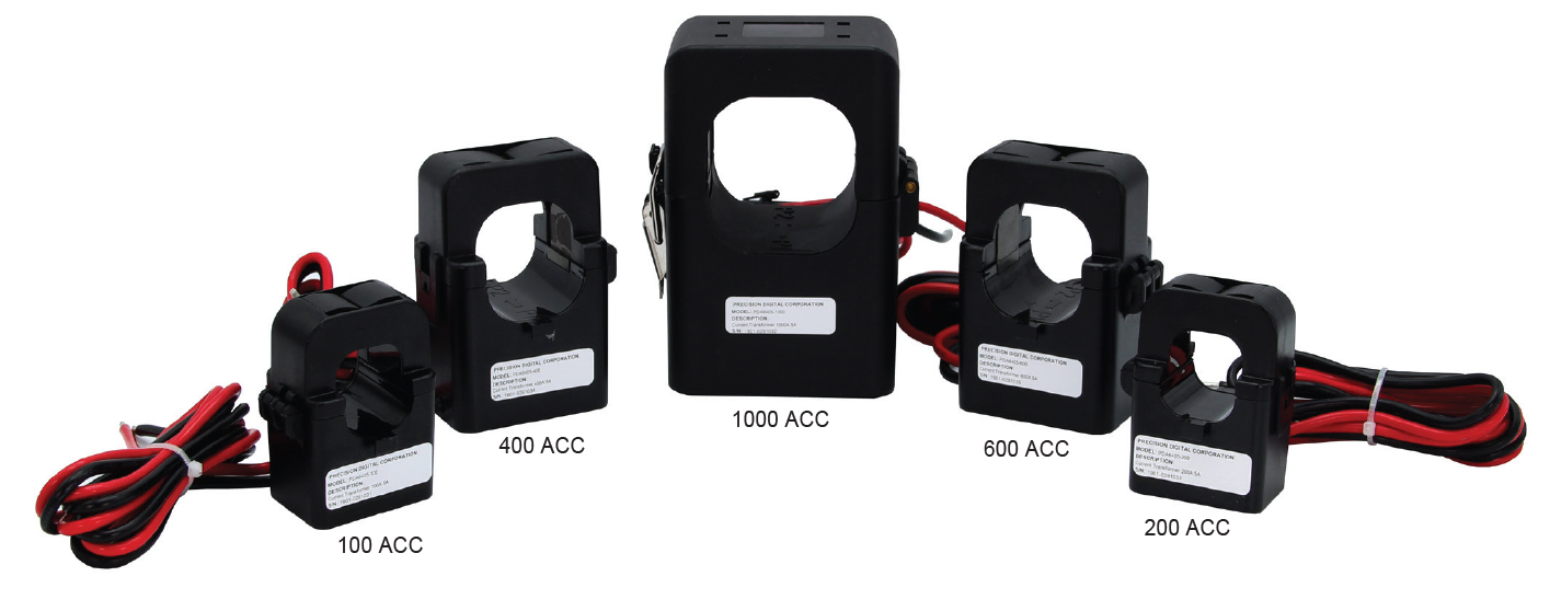
Precision Digital offers a line of split core AC current transformers that convert the high AC current flowing through a cable or wire to a 0-5 AAC output that can be displayed on a PD6400. The PDA6420 works with a PD6400 because it puts out a 4-20 mA signal. They are available in ranges of 100, 200, 400, 600, and 1000 AAC. These nonintrusive devices feature split core convenience for easy installation and are a cost effective solution for monitoring load or proof of operation. The PDA6420 current transformers are ideal for monitoring current loads on pumps, driving fans and blowers, and sensing the status of heating coils and lighting.
Specifications:
Current Range: 100A, 200A, 400A, 600A, and 1000A (based on model)
Output: 0-5 A
Accuracy: +/- 1%
Burden: 2VA
Insulation Voltage: CAT IV 250 or CAT III 600VAC
Maximum Primary Voltage: 5000 VAC (Insulated Conductor)
Phase Angle: Less than 2 degrees at 50% of rated current
Frequency Range: 50/60 Hz
Operating Temperature: -40 to 55°C
Humidity: 0-95% RH non-condensing, Indoor use only
Pollution Degree: 2
Leads: 18AWG 1.0 m cable
UL File Number: UL recognized for US and Canada (E341727)
Digital Communications
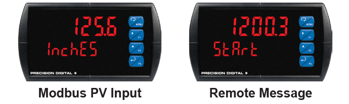
Modbus® RTU Serial Communications
With the purchase of a serial communication adapter, PROVU meters can communicate with any Modbus Master device using the ever-popular Modbus communications protocol that is included in every PROVU. In addition to the typical Modbus capabilities of reading PVs and writing set points, below are some examples of other things that can be done with the meter’s Modbus communications:
- Send a 6-character message to lower display upon an event
- Convert a digital value to a 4-20 mA signal
- Remote user control (i.e. change set points, acknowledge alarms)
- Input a Modbus digital PV (in place of analog input)
- Remote override of any, or all, relays and analog outputs

Serial Communication Devices
Precision Digital provides a variety of serial communication devices to interface the ProVu meter with other devices. For more information visit predig.com/ProVuSerialDevices.
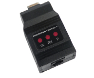
PDA1232 & PDA1485 Communication Modules
Serial communications on the PROVU meter can be added anytime with external PDA1232 (RS-232) or PDA1485 (RS-485) communication adapters. Free Modbus protocol is included for use with the PROVU serial communications modules.
Serial Adapters & Converters*
 PDA1232
ProVu RS-232 Serial Adapter | 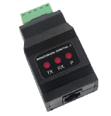 PDA1485
ProVu RS-485 Serial Adapter | 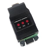 PDA7485-I
RS-232 to RS-422/485 Isolated Converter |
 PDA8232-N
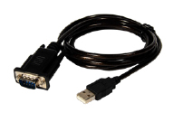
USB to RS-232 Non-Isolated Converter | 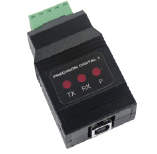 PDA8485-I
USB to RS-422/485 Isolated Converter |  |
*All adapters and connectors supplied with appropriate cables.
Field Expansion Modules
Add functionality to the PD6400 n the field with easy-to install external expansion modules. External expansion modules are available for RS-232 or RS-485 communications, digital I/O, 4 relays and dual 4-20 mA outputs. The menu items for these modules do not appear until the module is connected, simplifying the basic menu. Relay and digital I/O modules are shown below with optional DIN rail mounting kit, P/N PDA1002.
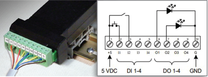
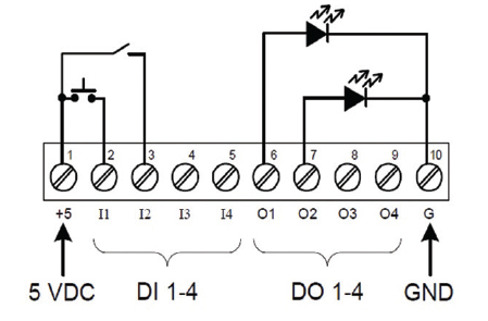
PDA1044 I/O Expansion Module
Four digital inputs and four digital outputs are available per expansion module. The PROVU meter will accept two of these modules. External digital inputs can function similarly to the front panel function keys or on-board digital input F4. They can be configured to trigger certain events (i.e. acknowledge/ reset alarms) or mimic front panel keys. The I/O module can be used to configure the PROVU remotely, in essence giving the user control of the four front panel push buttons.
Digital outputs can be used to remotely monitor PROVU’s alarm relay output states, or the states of a variety of actions and functions executed by the meter.
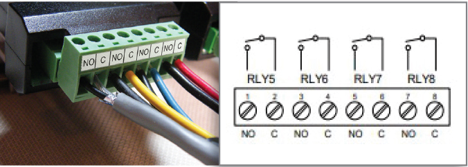
PDA1004 Relay Expansion Module
An external module containing four 3 A Form A (SPST) relays can be added to the PROVU at anytime. Removable screw terminal blocks accept 12 to 22 AWG wire.
PDA1011 Dual Isolated 4-20 mA Output Module
In addition to the on-board 4-20 mA output option, the PD6400 is also available with an external module that provides two more isolated 4-20 mA outputs. This allows the user to have separate 4-20 mA outputs for current, voltage and apparent power. relays can be added to the PROVU at anytime. Removable screw terminal blocks accept 12 to 22 AWG wire.
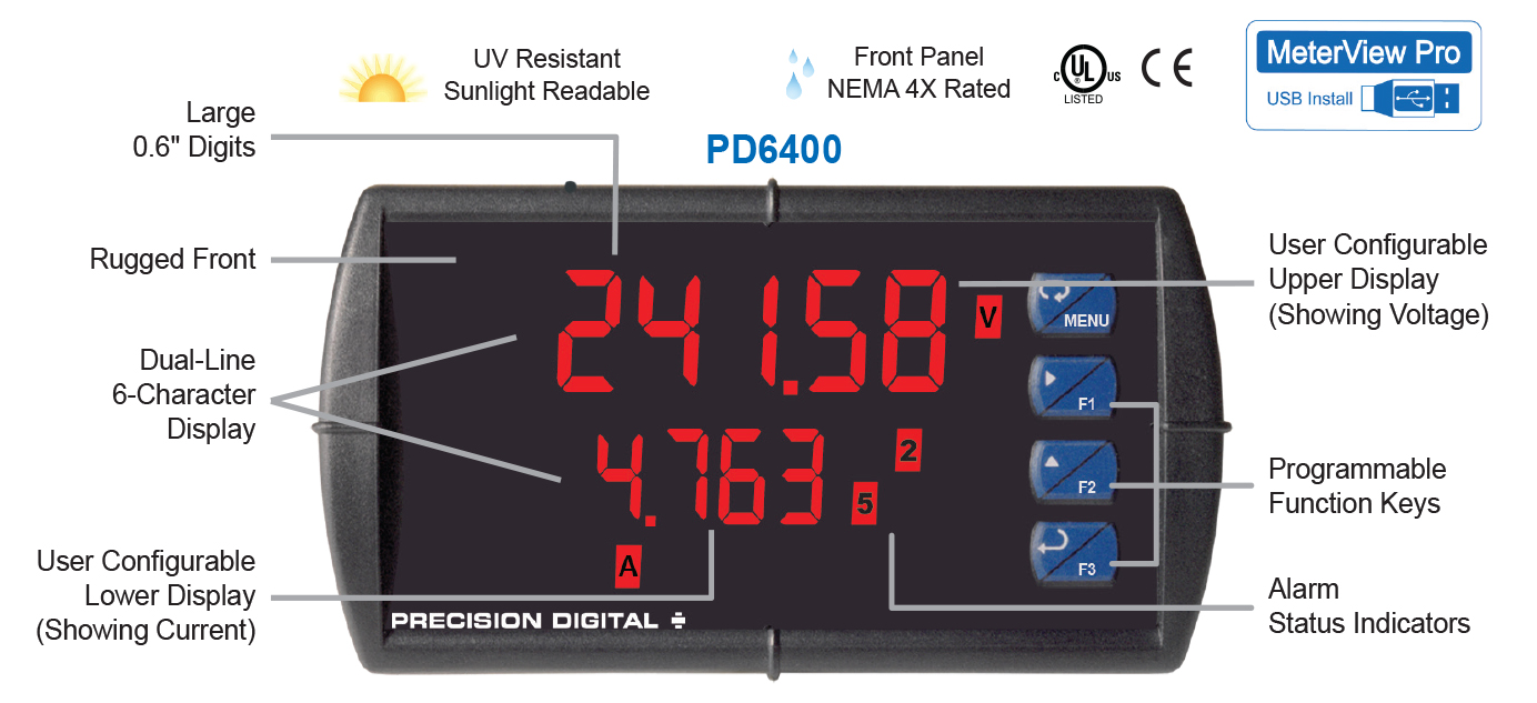
Physical Features
The ProVu is designed for ease-of-use in industrial applications. Considerations include a NEMA 4X front panel, wide operating temperature range, removable screw terminal connectors, snap in place mounting brackets, forgiving panel cutout requirement, and UL Listing for electrical safety. All of these features are backed by a 3-year warranty.
Type 4X / NEMA 4X Front Panel
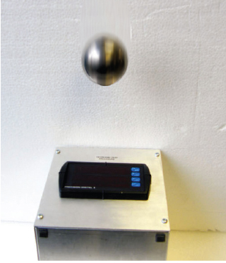 | Not only does the ProVu’s front panel UL Type 4X approval indicate it is waterproof, but it also indicates it is rugged. Part of the UL Type 4X test is to drop a 2 inch solid stainless steel ball from 8 feet on top of the meter’s faceplate. |
Wide Operating Temperature Range
The ProVu can operate from -40 to 65°C (-40 to 150°F) meaning it can be installed in a wide variety of indoor and outdoor industrial applications. And over this range, the ProVu will drift no more than 0.005% of calibrated span/°C max from 0 to 65°C ambient and 0.01% of calibrated span/°C max from -40 to 0°C ambient.
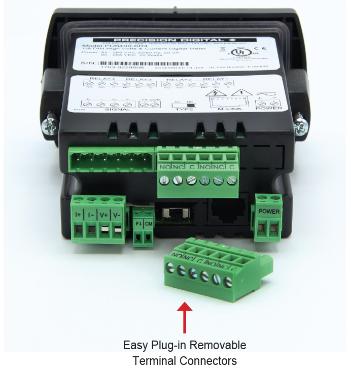
Removable Screw Terminal Connectors
Industrial applications require screw terminal connections for easy field wiring and the ProVu goes one step further in convenience by making them removable also.
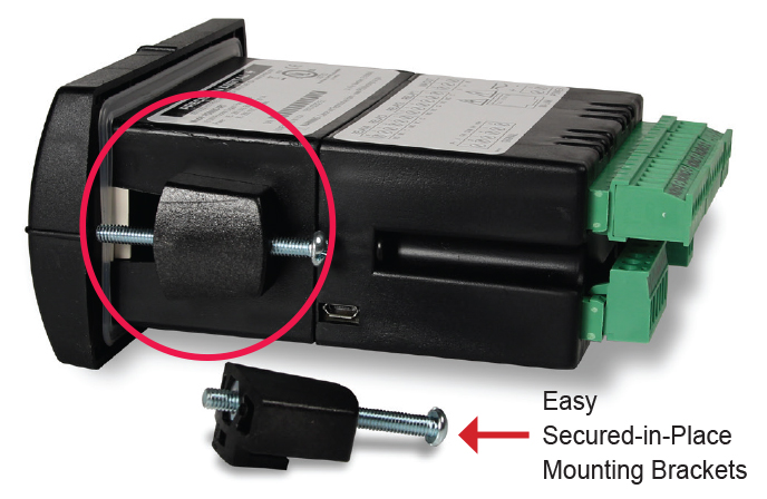
Secured-in-Place Rugged Mounting Brackets
If you’re installing the ProVu outdoors in the hot or cold weather, the last thing you want to do is fumble around with mounting brackets that don’t stay in place. The ProVu’s mounting brackets can be easily secured into place and then screwed down to the panel. These brackets are rugged so they can be tightened to the panel to provide a solid NEMA 4X seal.
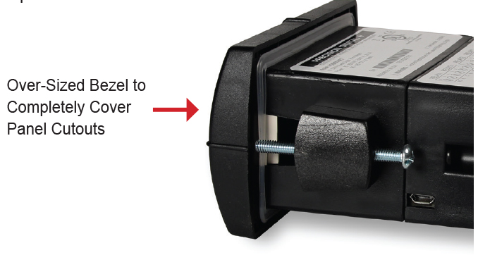
Forgiving Panel Cutout Requirement
The ProVu’s bezel has been oversized to allow for not perfectly executed panel cutouts where NEMA 4X seal is not required.
UL Listing for Electrical Safety
UL & C-UL Listed: USA & Canada
UL 508 Industrial Control Equipment
UL File Number: E160849
Front Panel: UL Type 4X, NEMA 4X, IP65; panel gasket provided
Low Voltage Directive: EN 61010-1:2010 Safety requirements for measurement, control, and laboratory use
USB Port for Easy Connection to MeterView Pro Free Software
Operational Features
Function Keys, F4 Terminal, Digital Inputs
There are three ways the user can interact with the ProVu to perform a variety of useful functions:
1. Three Front Panel Function Buttons
The default settings for the function keys are:

2. F4 On-Board Digital Input
The PD6400 includes a digital input as standard. This digital input can operate with the interlock relays feature, force relays on from a signal from a PLC or relay on other equipment, and much more. This is ideal for installations where the meter is inaccessible behind a cover, or where an additional function key is needed for customized operation.
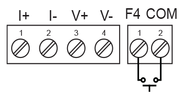
The F4 terminal is particularly useful for wiring up a remote switch to reset the relays as shown here:
3. Optional 4 Digital Input/Output Module PDA1044
With these three methods, the ProVu can be programmed to trigger certain events (i.e acknowledge relays, reset max and/or min, disable/enable output relays, or hold current relay states), provide direct menu access points and more.
Remote Operation Using PDA2364-MRUE Control Station
The PD6400's four internal programming and operations buttons can be remotely controlled by using the PDA2364-MRUE 4-button control station accessory as shown in the diagram below.
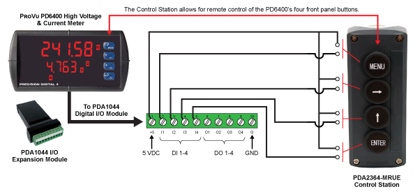
Remote Operation of Front Panel Buttons
The user can operate the front panel buttons from a remote location by using digital inputs programmed in the following manner:

Max / Min Display
Max/Min (or Peak/Valley) is standard on the ProVu PD6400. Either display can be configured to show either maximum or minimum excursion since last reset. The displays can also be configured to toggle between Max and Min values. Both values can be simply reset from the front panel.
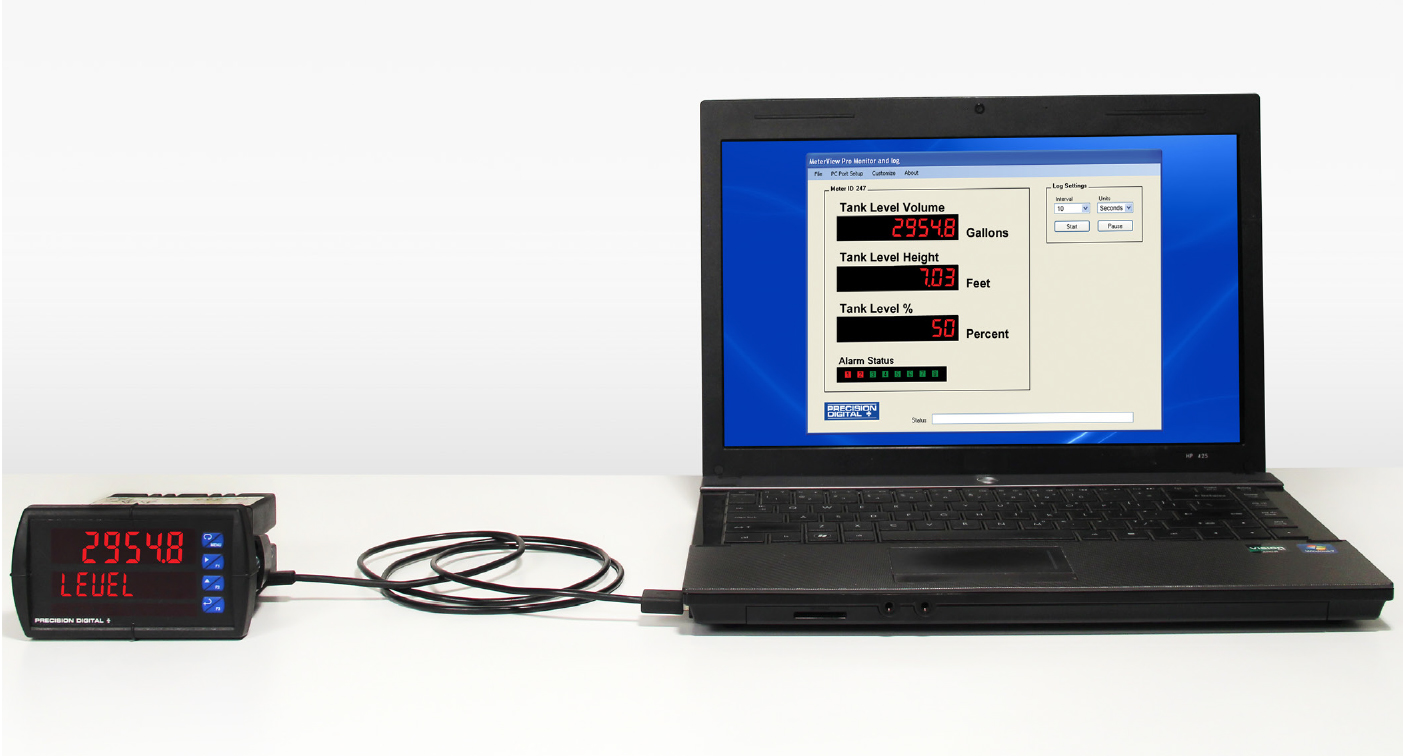
MeterView Pro Monitoring & Datalogging Software
Not only does free MeterView Pro software greatly simplify setup and programming of the ProVu, it can also be used to monitor and datalog your process.
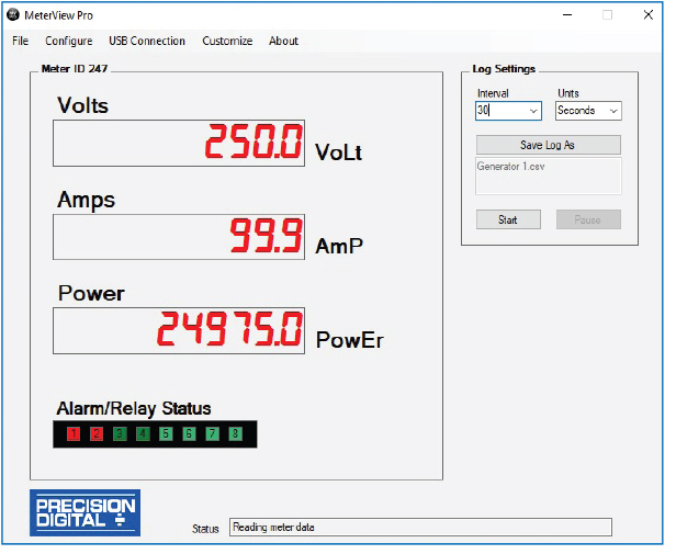
- Custom Tags: i.e. Power
- Custom Units: i.e. Amps, Volts
- Alarm Status Indicators
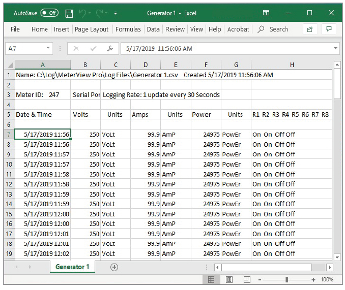
Datalog Report
Collected data logger information can be sent to a CSV file for importing into a spreadsheet program. Below is an example of one such file. Of course, once within the spreadsheet, much can be done to customize the data.
Relay Control
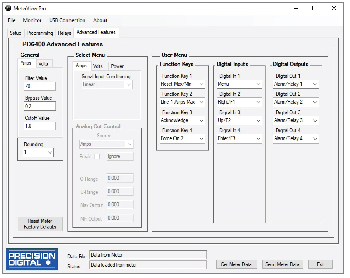
Relays can be controlled from MeterView Pro for testing purposes. This is commonly done to determine whether the relays are functioning properly. In the Setup window, under Relay and Digital Out Test you have the option of selecting the relays you want in an ON state or OFF state and also whether you want to leave the relays in manual control or to return them to automatic operation.

Function Key, Digital Inputs, & Digital Outputs Descriptions
The following table describes the actions that ProVu function keys and digital inputs can be programmed to perform. The table also describes how the digital outputs can be used to remotely monitor the ProVu’s alarm relay states, or the states of a variety of actions and functions executed by the meter.
| Display | Description | Item |
 | Reset the stored maximum display value | FK, DI, DO |
 | Reset the stored minimum display value | FK, DI, DO |
 | Reset the stored maximum & minimum display values | FK, DI, DO |
 | Capture tare and zero the display | FK, DI, DO |
 | Reset captured tare and resume normal operation | FK, DI, DO |
 | Directly access the relay menu | FK, DI |
 | Directly access the set point menu for relay 1 (*through 8) | FK, DI |
 | Disable all relays until a button assigned to enable relays (Rly E) is pressed | FK, DI |
 | Enable all relays to function as they have been programmed | FK, DI |
 | Hold current relay states and analog output as they are until a button assigned to enable relays (Rly E) is pressed | FK, DI |
 | Hold the current display value, relay states, and analog output momentarily while the function key or digital input is active. The process value will continue to be calculated in the background. | FK, DI |
 | Display maximum display value on line 1 | FK, DI |
 | Display minimum display value on line 1 | FK, DI |
 | Display maximum & minimum display values on line 1 | FK, DI |
 | Display maximum display value on line 2 | FK, DI |
 | Display minimum display value on line 2 | FK, DI |
 | Display maximum & minimum display values on line 2 | FK, DI |
 | Force relay 1 (*through 4) into the on state. This is used in conjunction with a digital input expansion module to achieve interlock functionality. | FK, DI |
 | Directly access the control menu | FK, DI |
 | Disable the selected function key or digital I/O | FK, DI |
 | Acknowledge all active relays that are in a manual operation mode such as auto-manual or latching | FK, DI, DO |
 | Directly access the reset menu | FK, DI |
 | Mimic the menu button functionality (digital inputs only) | DI |
 | Mimic the right arrow/F1 button functionality (digital inputs only) | DI |
 | Mimic the up arrow/F2 button functionality (digital inputs only) | DI |
 | Mimic the enter/F3 button functionality (digital inputs only) | DI |
 | Provide indication when alarm 1 (*through 8) has been triggered (digital outputs only) | DO |
FK: Function Keys DI: Digital Inputs DO: Digital Outputs

NEMA 4 & 4X Field Enclosures
Precision Digital offers a variety of rugged enclosures that provide a high degree of protection against harsh operating environments. Thermoplastic and stainless steel NEMA 4X, and painted steel NEMA 4 enclosures for up to 10 ProVu meters are available. In addition, Precision Digital offers a Light / Horn that can be mounted to most of these enclosures to provide visual and audible indication of alarms.


Plastic Enclosures (Externally Mounted)
PDA2300 Series (Covers with Hinge & Hasp)
TThis is Precision Digital’s most economical line of enclosures for the ProVu. The meter mounts through a hinged cover with a SS hasp allowing for easy access to meter wiring. Enclosures are available for 1 through 10 ProVus.
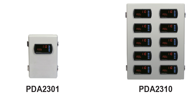
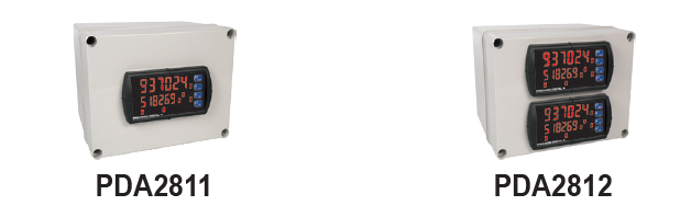
PDA2800 Series (Covers with Screws)
This is Precision Digital’s smallest line of enclosures for the ProVu. The meter mounts through the cover that screws to the base of the enclosure. Available for 1 and 2 ProVus.
Plastic Enclosures (Internally Mounted)
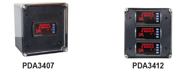
PDA3400 Series (Covers with screws)
This is Precision Digital’s only line of enclosures for the ProVu where the meter is fully housed inside the enclosure. Enclosures are available for 1, 2 and 3 ProVus.
Stainless Steel Enclosures (Externally Mounted)
PDA2600 Series (Covers with Hinge & Hasp)
This is Precision Digital’s stainless steel line of enclosures for the ProVu. The meter mounts through a hinged cover with a SS hasp allowing for easy access to meter wiring. Enclosures are available for 1 through 6 ProVus.
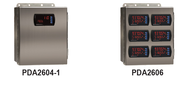
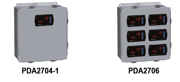
Steel Enclosures (Externally Mounted)
PDA2700 Series (Covers with Hinge & Hasp)
This is Precision Digital’s painted steel line of enclosures for the ProVu. The meter mounts through a hinged cover with a hasp allowing for easy access to meter wiring. Enclosures are available for 1 through 6 ProVus.
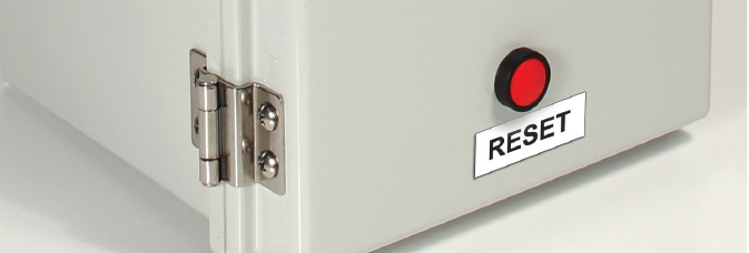
Light / Horn & Reset Button Mounted to Enclosure
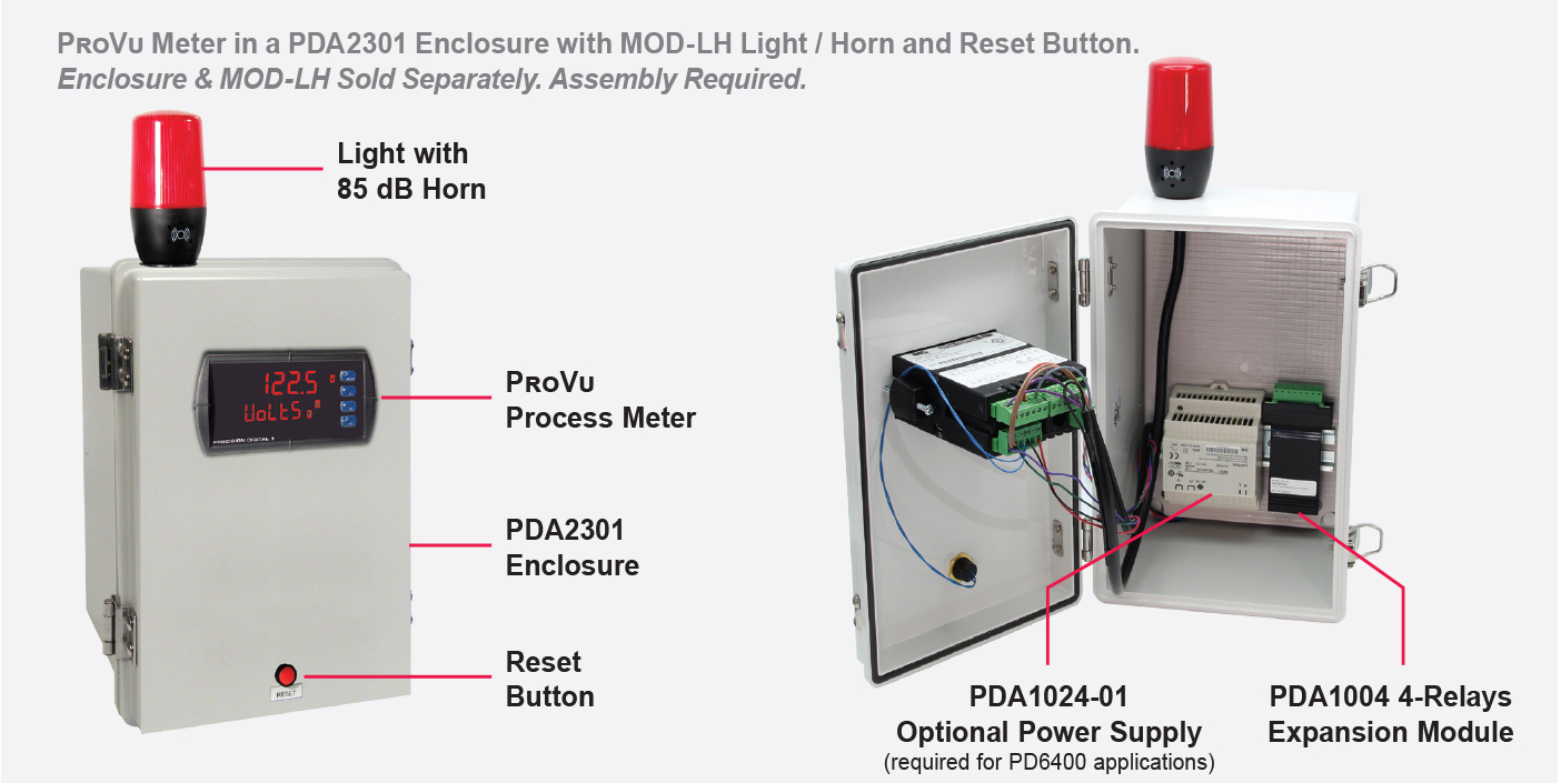
Overview
Precision Digital offers a wide variety of NEMA 4 and NEMA 4X enclosures that can be equipped with MOD-LH Light / Horn and Reset Button. When MOD-LH is ordered, the accompanying enclosure on the order comes with the holes pre-drilled for the Light / Horn and the Reset Button and the user performs the mounting and wiring. Meter and enclosure are sold separately. The Light / Horn and the Reset Button can also be ordered as separate items and the user performs all hole-drilling, mounting and wiring as desired. The light and horn can be controlled independently of each other via separate relays on the ProVu meter; and since the meter's relays can be reset in a variety of ways, there are several ways the Light / Horn option can operate. For instance, the horn can be programmed to silence at any time via the Reset Button or F3 front panel button on the ProVu, and light to reset automatically when the alarm clears as the following table illustrates:
| Relay # | Connected to | Typical reset method
(user selectable) |
| 1 | Flashing Light(1) | Auto reset |
| 2 | Horn | Silence with Reset Button at any time |
| 3 | User Device | As user desires |
| 4 | User Device | As user desires |
1. Light can be wired to flash or stay steady on
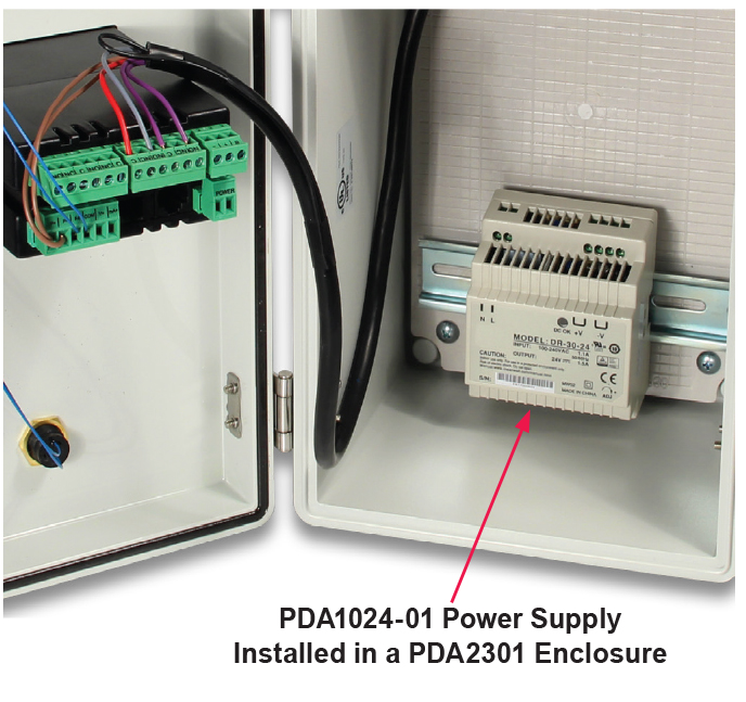
Note: For Light/Horn applications using the PD6400, an external power supply such as Precision Digital’s PDA1024-01 must be used to power the Light / Horn.
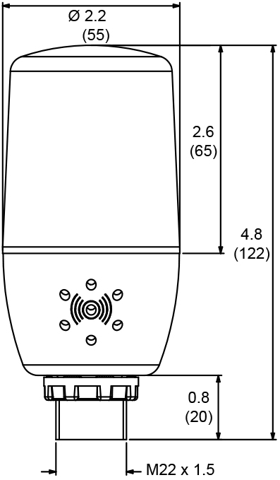
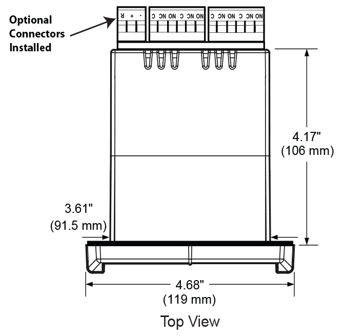
Dimensions Units: Inches (mm)

PDA1024-01 24 VDC DIN Rail Power Supply
For Light/Horn applications using the PD6400, an external power supply such as Precision Digital’s PDA1024-01 must be used to power the Light / Horn.
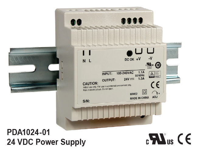
| Input Voltage | 85 ~ 264VAC 120 ~ 370VDC |
| Output Voltage | 21.6 ~ 26.4 VDC; ±10% 1.5A rated current |
| Input Frequency | 47 ~ 63Hz |
| AC Current | 0.88A/115VAC 0.48A/230VAC |
| Connections | Two terminals provided for +V and -V to simplify wiring of multiple devices |
| Operating Temperature | -20° to 60°C |
| Safety Standards | UL60950-1, TUV EN60950-1 Approved, Design refer to EN50178 |
| EMC | Compliance to EN55011, EN55022 (CISPR22) Class B, EN61000-3-2, -3 EN61000-4-2, 3, 4, 5, 6, 8, 11, ENV50204, EN55024, EN61000-6-1, EN61204-3 Light industry, Criteria A |
| Dimensions | 3.07" x 3.66" x 2.20" (78 mm x 93 mm x 56 mm) (W xHxD) |
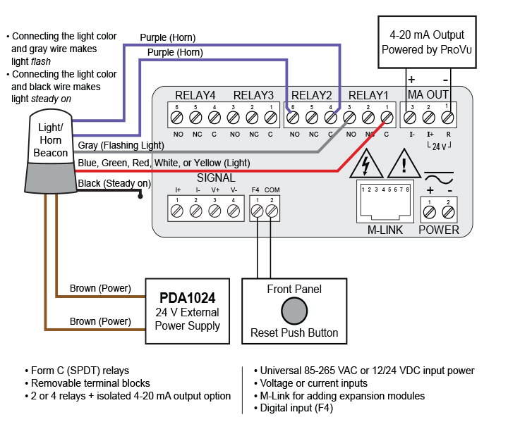
Wiring Connections for MOD-LH Models
The following diagrams are for MOD-LH models with a single color light. See MOD-LH manual for wiring connections for MOD-LH5CB1 and MOD-LH3CB1-RYG models.
Using External Power Supply (PDA1024-01)
Dimensions Units: Inches (mm)
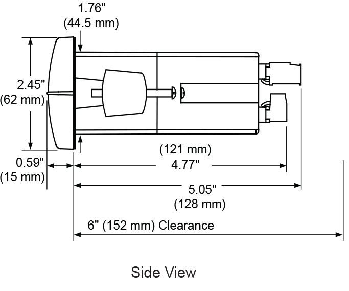
Notes:
1. Panel cutout required: 1.772" x 3.622" (45 mm x 92 mm)
2. Panel thickness: 0.040 - 0.250" (1.0 mm - 6.4 mm)
3. Mounting brackets lock in place for easy mounting
4. Clearance: Allow 6" (152 mm) behind the panel
Connections