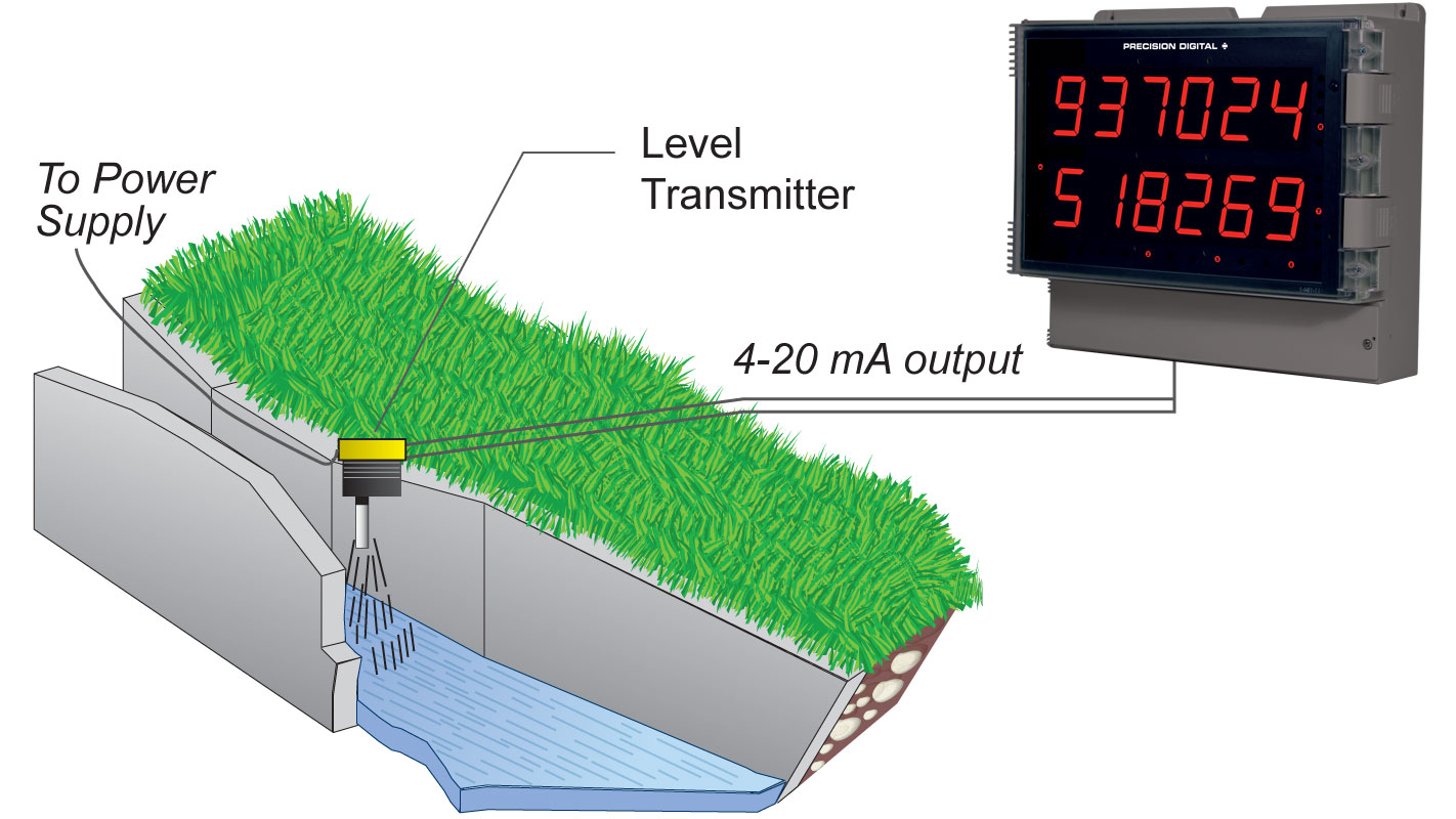
General
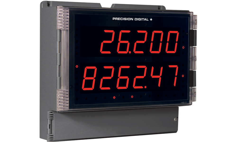
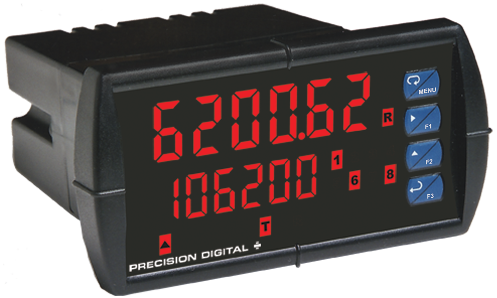
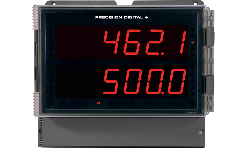
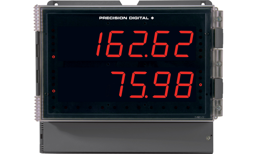
Display: Two lines with 1.8" (46 mm) high digits, red LEDs; 6 digits per line (-99999 to 999999), with lead zero blanking
Display Intensity: Eight user selectable intensity levels
Display Update Rate: 5/second (200 ms)
Overrange: Display flashes 999999
Underrange: Display flashes -99999
Display Assignment: The upper and lower displays may be assigned to rate, total, grand total, alternate (rate/total, rate/grand total, rate/units, total/units, and grand total/units), max/min, units (lower display only), set points, or Modbus input. Additional displays are available if parameter total is off, abd parameter d-SCAL is on: gross, alternating gross/net, PV1, PV2, and PCT (refer to PD6000 instruction manual).
Programming Methods: Four SafeTouch through-glass buttons when cover is installed. Four internal pushbuttons when cover is removed.
F4 Digital Input Contacts: 3.3 VDC on contact. Connect normally open contacts across F4 to COM.
F4 Digital Input Logic Levels: Logic High: 3 to 5 VDC; Logic Low: 0 to 1.25 VDC
Noise Filter: Programmable from 2 to 199 (0 will disable filter)
Filter Bypass: Programmable from 0.1 to 99.9% of calibrated span
Recalibration: All ranges are calibrated at the factory. Recalibration is recommended at least every 12 months.
Max/Min Display: Max (Peak) / min (Valley) readings reached by the process are stored until reset by the user or until power to the meter is cycled.
Password: Three programmable passwords restrict modification of programmed settings and two prevent resetting the totals.
Non-Volatile Memory: All programmed settings are stored in non-volatile memory for a minimum of ten years if power is lost.
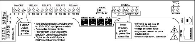
Power Options: 85-265 VAC 50/60 Hz, 90-265 VDC, 20 W max or 12-24 VDC ± 10%, 15 W max. Powered over USB for configuration only.
Isolated Transmitter Power Supply: Terminals P+ & P-: 24 VDC ± 10%. 12-24 VDC powered models selectable for 24, 10, or 5 VDC supply (internal P+/P- switch). 85-265 VAC models rated @ 200 mA max, 12-24 VDC powered models rated @ 100 mA max, @ 50 mA max for 5 or 10 VDC supply.
Fuse: Required external fuse: UL Recognized, 5 A max, slow blow; up to 6 meters may share one 5 A fuse.
Normal Rejection Mode: Greater than 60 dB at 50/60 Hz
Isolation: 4 kV input/output-to-power line. 500 V input-to-output or output-to-P+ supply.
Overvoltage Category: Installation Overvoltage Category II: Local level with smaller transient overvoltages than Installation Overvoltage Category III.
Environmental:T6 Class operating temperature range Ta = -40 to 60°C
T5 Class operating temperature range Ta = -40 to 65°C
Max Power Dissipation: Maximum power dissipation limited to 15.1 W.
Connections: Removable screw terminal blocks accept 12 to 22 AWG wire, RJ45 for external relays, digital I/O, and serial communication adapters.
Enclosure: UL Type 4X, IP65 rated. Polycarbonate & glass blended plastic case, color: gray. Includes four PG11 through-hole conduit openings, with two factory installed PG11, IP68, black nylon threaded hole plugs with backing nuts.
Wall Mounting: Four (4) mounting holes provided for mounting meter to wall.
Pipe Mounting: Optional pipe mounting kit (PDA6260) allows for pipe mounting. Sold separately.
See PD2-6200 manual for instructions.Dimensions: 10.63" x 12.59" x 4.77" (270 mm x 319.7 mm x 121.2 mm) (H x W x D)
Weight: 6.10 lbs (2.76 kg)
UL File Number: UL & C-UL Listed. E160849; 508 Industrial Control Equipment.
Warranty: 3 years parts & labor
USB Connection: Compatibility: USB 2.0 Standard, Compliant Connector Type: Micro-B receptacle
Cable: USB A Male to Micro-B Cable
Driver: Windows 98/SE, ME, 2000, Server 2003/2008, XP 32/64-Bit, Vista 32/64-Bit, Windows 7 32/64-Bit, Windows 10 32/64-Bit
Power: USB Port
Analog Inputs
Inputs: Field selectable: 0-20, 4-20 mA, ±10 VDC (0-5, 1-5, 0-10 V), Modbus PV (Slave)
Accuracy: ±0.03% of calibrated span ±1 count, square root & programmable exponent accuracy range: 10-100% of calibrated span
Temperature Drift: 0.005% of calibrated span/°C max from 0 to 65°C ambient, 0.01% of calibrated span/°C max from -40 to 0°C ambient
Math Function: Linear, square root, programmable exponent, or round horizontal tank volume calculation.
Multi-Point Linearization: 2 to 32 points
Programmable Exponent: 1.0001 to 2.9999
Low-Flow Cutoff: 0-999999 (0 disables cutoff function)
Decimal Point: Up to five decimal places or none: d.ddddd, dd.dddd, ddd.ddd, dddd.dd, ddddd.d, or dddddd.
Calibration Range:| Input Range | Minimum Span Input 1 & 2 |
| 4-20 mA | 0.15 mA |
| ±10 V | 0.10 V |
An Error message will appear if input 1 and input 2 signals are too close together.Input Impedance: Voltage ranges: greater than 1 MΩ. Current ranges: 50 - 100 Ω (depending on resettable fuse impedance).
Input Overload: Current input protected by resettable fuse, 30 VDC max. Fuse resets automatically after fault is removed.
HART Transparency: Analog input will not interfere with existing HART communications on the wired 4-20 mA signal
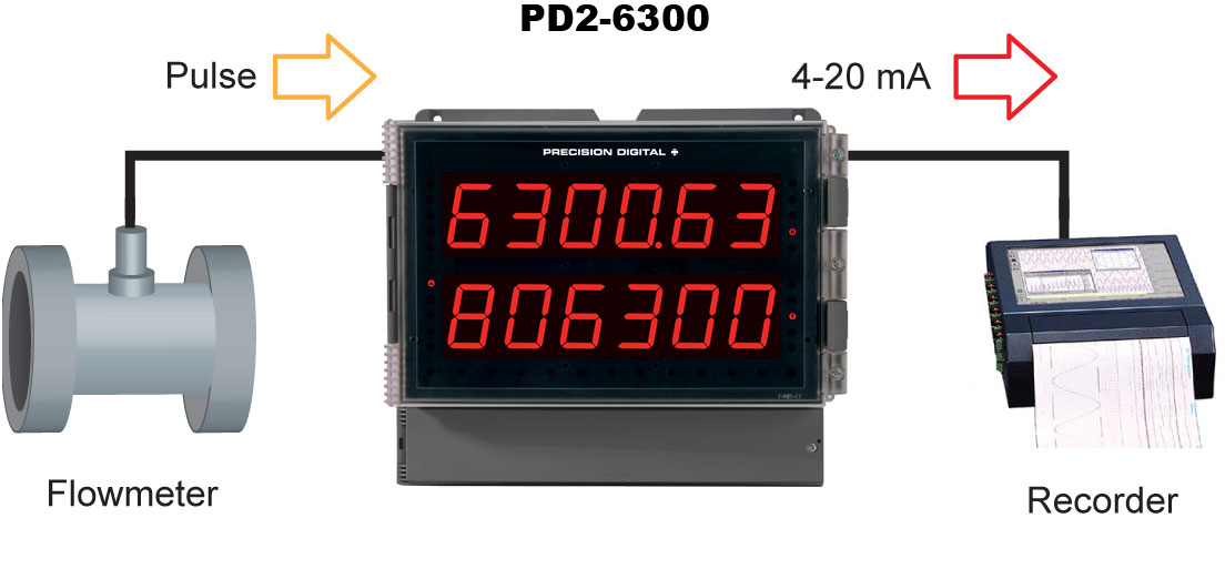
Rate/Totalizer
Rate Display Indication: 0 to 999999, lead zero blanking. "R" LED illuminates while displaying rate. Total Display & Total Overflow: 0 to 999,999; automatic lead zero blanking. "T" LED is illuminated while displaying total and "GT" for grand total. Up to 999,999,999 with total-overflow feature. "oF" is displayed to the left of total overflow and ▲ LED is illuminated.
Total Decimal Point: Up to five decimal places or none: d.ddddd, dd.dddd, ddd.ddd, dddd.dd, ddddd.d, or dddddd. Total decimal point is independent of rate decimal point.
Totalizer: Calculates total based on rate and field programmable multiplier to display total in engineering units. Time base must be selected according to the time units in which the rate is displayed. Selectable up/down count. Total Conversion Factor: 0.00001 to 59,999
Totalizer Rollover: Totalizer rolls over when display exceeds 999,999,999. Relay status reflects the display value.
Total Overflow Override: Program total reset for automatic with 0.1 second delay and set point 1 for 999,999
Totalizer Presets: Up to eight, user selectable under Setup menu. Any set point can be assigned to total and may be programmed anywhere in the range of the meter for total alarm indication.
Programmable Total Reset Delay: 0.1 to 999.9 seconds; applied to the first relay assigned to total or grand total. If the meter is programmed to reset total to zero automatically when the preset is reached, then a delay will occur before the total is reset.
Total Reset: Via front panel button, external contact closure on digital inputs, automatically via user selectable preset value and time delay, or through serial communications.
Total Reset Password: Total and grand total passwords may be enteredto prevent resetting the total or grand total from the front panel.
Non-Resettable Total: The grand total can be programmed as a nonresettable total by entering the password "050873".
Caution: Once the Grand Total has been programmed as "non-resettable" the feature cannot be disabled.Relays
Rating: 2 or 4 SPDT (Form C) internal and/or 4 SPST (Form A) external; rated 3 A @ 30 VDC and 125/250 VAC resistive load; 1/14 HP (≈ 50 W) @125/250 VAC for inductive loads
Noise Suppression: Noise suppression is recommended for each relay contact switching inductive loads.
Relay Assignment: Relays may be assigned to rate, total, or grand total.
Deadband: 0-100% of span, user programmable
High or Low Alarm: User may program any alarm for high or low trip point. Unused alarm LEDs and relays may be disabled (turned off).
Relay Operation: automatic (non-latching), latching (requires manual acknowledge), sampling (based on time), pump alternation control (2 to 8 relays), off (disable unused relays), and manual on/off control mode.
Relay Reset: User selectable via front panel buttons, digital inputs, or PC
1. Automatic reset only (non-latching), when input passes the reset point or total is reset to zero.
2. Automatic + manual reset at any time (non-latching).
3. Manual reset only, at any time (latching).
4. Manual reset only after alarm condition has cleared (latching).
Note: Front panel button or digital input may be assigned to acknowledge relays programmed for manual reset. Time Delay: 0 to 999.9 seconds, on & off relay time delays. Programmable and independent for each relay.
Fail-Safe Operation: Programmable and independent for each relay.
Note: Relay coil is energized in non-alarm condition. In case of power failure, relay will go to alarm state.Auto Initialization: When power is applied to the meter, relays will reflect the state of the input to the meter.
Isolated 4-20 mA Transmitter Output
Output Source: Rate/process, total, grand total, max, min, set points 1-8, manual control setting, or Modbus input
Scaling Range: 1.000 to 23.000 mA for any display range
Calibration: Factory calibrated: 4.000 to 20.000 = 4-20 mA output
Analog Output Programming: 23.000 mA maximum for all parameters: Overrange, underrange, max, min, and break
Accuracy: ±0.1% FS ±0.004 mA
Temperature Drift: 0.4 µA/°C max from 0 to 65°C ambient, 0.8 µA/°C max from -40 to 0°C ambient
Note: Analog output drift is separate from input drift.Isolated Transmitter Power Supply: Terminals I+ & R: 24 VDC ± 10%. Isolated from the input at >500 V. May be used to power the 4-20 mA output or other devices. All models rated @ 40 mA max.
External Loop Power Supply: 35 VDC maximum
Output Loop Resistance:| Power supply | Minimum | Maximum |
| 24 VDC | 10Ω | 700Ω |
| 35 VDC (external) | 100Ω | 1200Ω |
Serial Communications
Compatability: EIA-485
Connectors: Removable screw terminal connector
Max Distance: 3,937' (1,200 m) max
Status Indication: Separate LEDs for Power (P), Transmit (TX), and Receive (RX)
Protocol: Modbus
® RTU
Meter Address/Slave ID: 1 - 247
Baud Rate: 300 - 19,200 bps
Transmit Time Delay: Programmable between 0 and 199 ms or transmitter always on for RS-422 communication
Data: 8 bit (1 start bit, 1 or 2 stop bits)
Parity: Even, odd, or none with 1 or 2 stop bits
Byte-to-Byte Timeout: 0.01 - 2.54 second
Turn Around Delay: Less than 2 ms (fixed)
Digital Inputs and Outputs
Channels: 4 digital inputs & 4 digital outputs per module
System: One expansion module may be added for a total of 8 inputs & 8 outputs
Note: The jumper located between the RJ45 connectors must be removed on the expansion module. Digital Input Logic: High: 3 to 5 VDC;
Low: 0 to 1.25 VDC
Digital Output Logic: High: 3.1 to 3.3 VDC;
Low: 0 to 0.4 VD
Source Current: 10 mA maximum output current
Sink Current: 1.5 mA minimum input current
+5 V Terminal: To be used as pull-up for digital inputs only. Connect normally open pushbuttons across +5 V & DI 1-4.
Warning: DO NOT use +5 V terminal (pin 1) to power external devices.
Function Assignment: The on-board digital inputs (1-4) are designed to mimic the behavior of the front panel buttons (Menu, F1, F2, & F3). If you wish to change their behavior, re-assign F1-F3 to the desired function, then change the corresponding digital input to match.
4-Relay Expansion Module
Relays: Four Form A (SPST) rated 3 A @ 30 VDC and 125/250 VAC resistive load; 1/14 HP (approx. 50 watts) @ 125/250 VAC for inductive loads.