Features
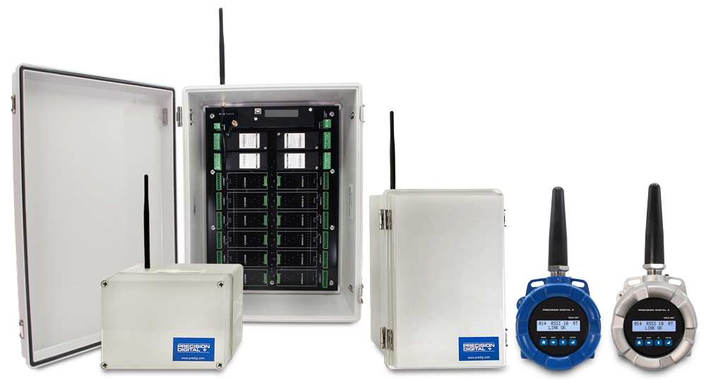
- Signal Wire Replacement System Consisting of Wireless Base Station and Field Units
- Wireless Point to Multi-Point Signal Wire Replacement for up to 32 4-20 mA Signals
- Range: 1 Mile Line-of-Sight Outdoor, 500 Feet Indoor; Repeaters Available to Extend Range
- Wireless Transmission Between Base Station and any Field Unit of
◦ 4-20 mA (Separate Signals to and from Base Station))
◦ Discrete (4 digital I/O Signals to and from Base Station))
◦ RS-485 Modbus - Inputs: (Wired to Field Units) 4-20 mA or 0-10 V (1), Discrete/Digital (up to 4), Modbus
- Outputs: (Wired to Field Units) 4-20 mA (1), Discrete/Digital (up to 4), Relays (2, opt), Modbus
- Base Station I/O Modules for 4-20 mA Inputs, 4-20 mA Outputs, Relay Outputs, Digital I/O
- Base Stations with slots for 2, 6, or 16 Field Installable I/O Modules and Modbus
- Loss of Signal (LoS) Digital Output
- PDA10 Signal Strength Survey Tool to "Try Before You Buy"
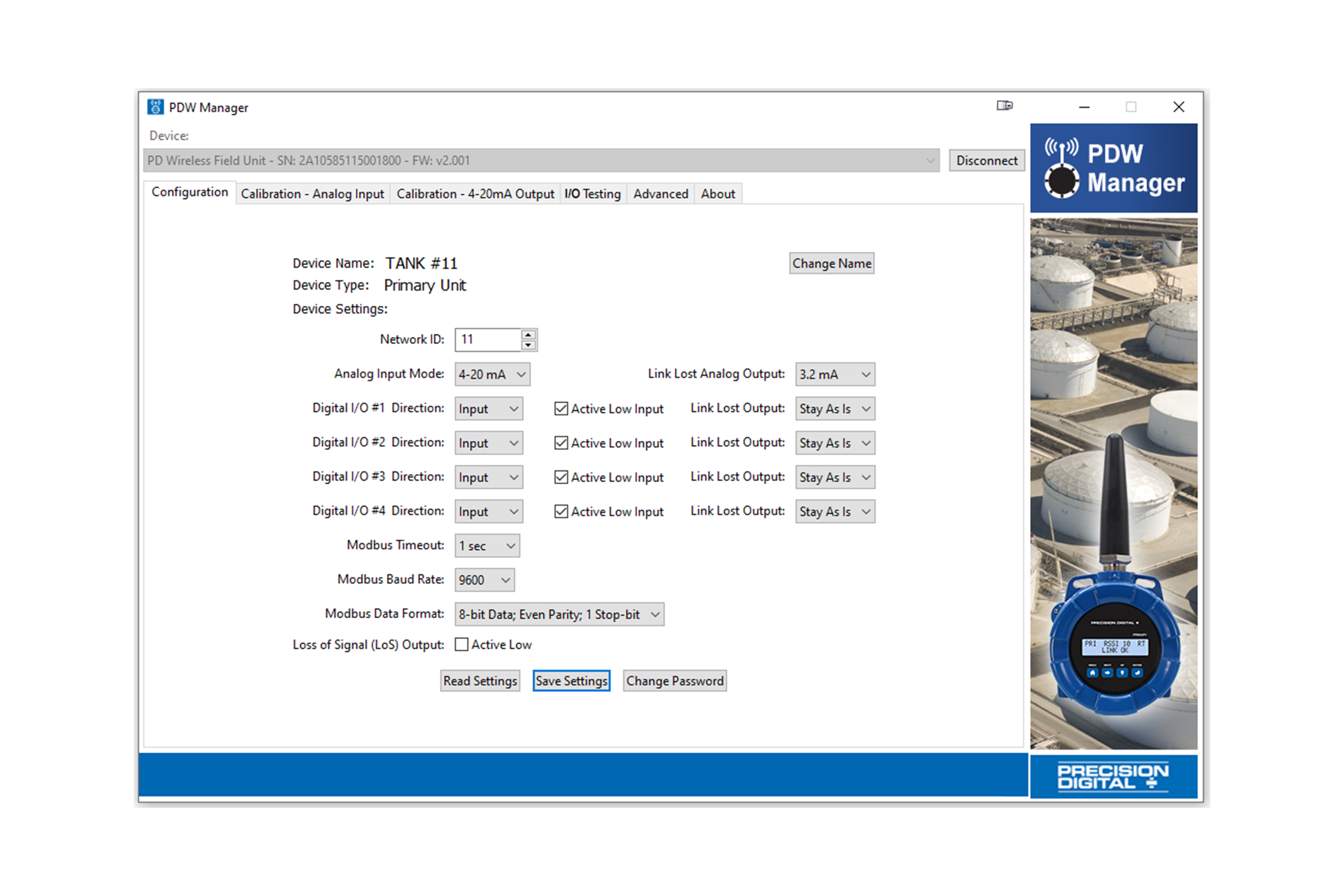
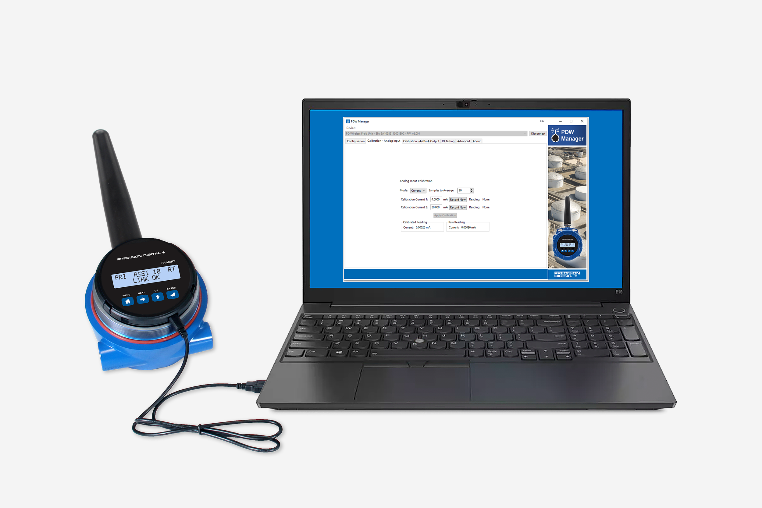
- Simple to Configure Using PDW Manager Programming Software and On-Board USB
- Device Communication Secured by Enabling 128-bit AES Encryption
- Password Protection
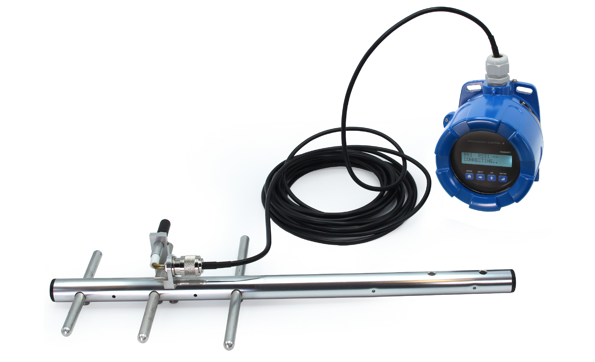
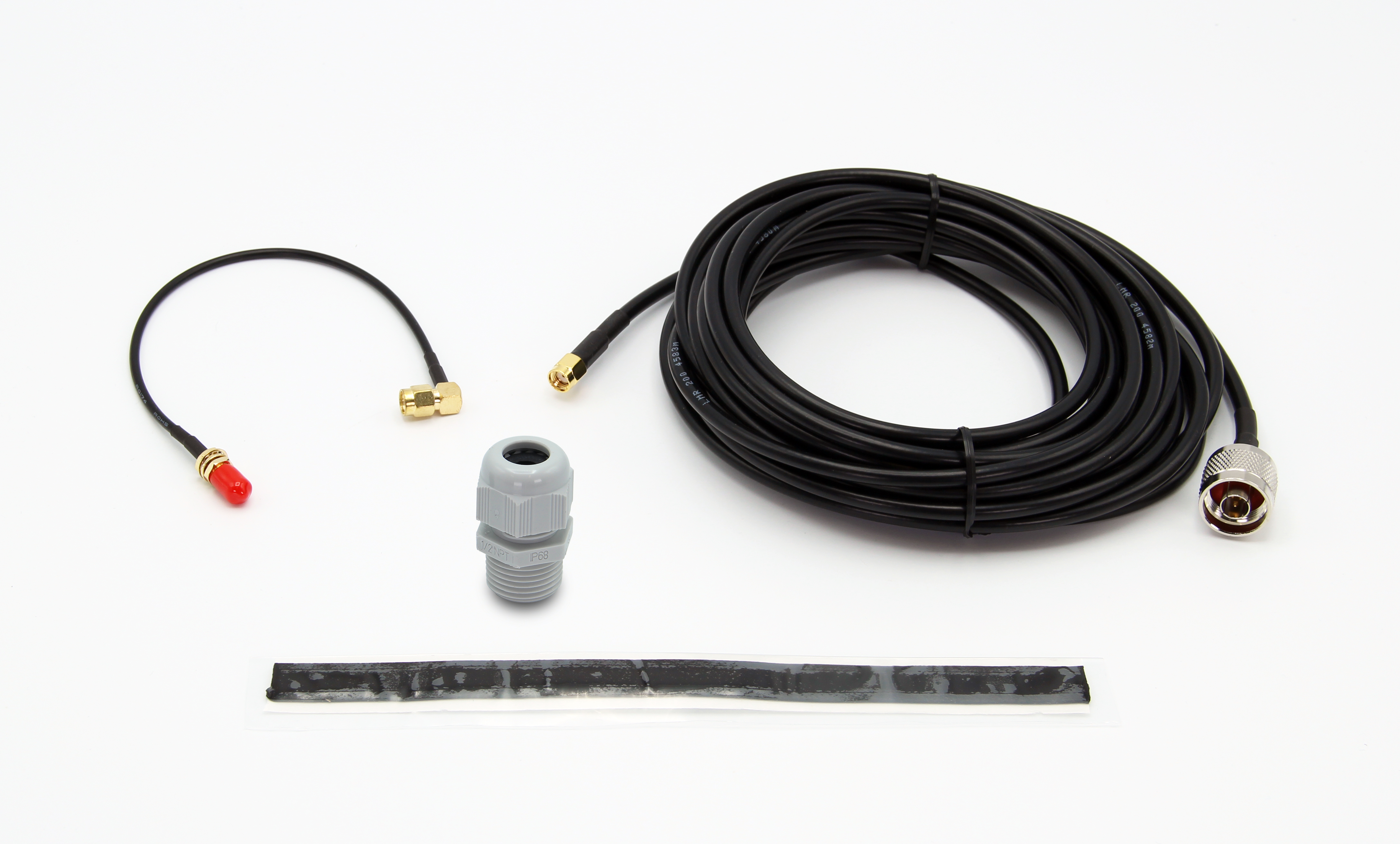
- Remote Yagi Directional Antennas Available
- Base Stations Housed in Plastic NEMA 4X Field Enclosures
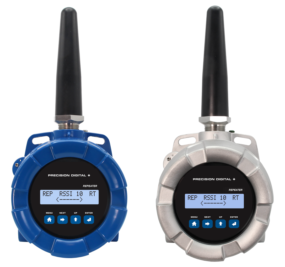
- Field Units Available in IP68, NEMA 4X Aluminum & Stainless Steel Enclosures
- Field Unit Operating Temperature Range: -55 to 75°C (-67 to 167°F)
- PCBs are Conformal Coated for Dust & Humidity Protection
- Power: 9-30 VDC, Base Station & Field Units
- 3-Year Warranty
Overview
Base Station

Field Unit

Signal Wire Replacement for Point to Multi-Point Industrial Wireless Applications
In its most basic form, the PDW90 consists of field units (up to 32) that accept 4-20 mA signals and transmits them wirelessly to a base station. The primary advantage of this system is how simple and economical it is to get multiple signals (not just 4-20 mA, also discrete (digital) and Modbus) from where you have them to where you need them – all without having to run wires!
The wireless communication between the field units and the base station is bi-directional. That means you can send 4-20 mA, discrete and Modbus signals from the field units to the base station and also send completely different 4-20 mA, discrete and Modbus signals from the base station to the field units. For instance, the field unit could send a 4-20 mA signal to the base station corresponding to the level in a tank and the base station could send a 4-20 mA sig-nal to the field unit to control a valve.
Field units are also equipped with four digital I/O that can each be independently programmed as an input or an output. A Loss of Signal warning is also available by connecting devices to the G and LS screw terminals.
To indicate alarm situations in the field, the field unit can be equipped with an optional, field installable, two relays module. These relays are rated Form A (SPST) 5A and are controlled by the digital outputs on the base station.
The base stations are available in configurations for 2, 6, or 16 I/O slots for a variety of field installable I/O modules. The available I/O modules are:
- Dual Analog Input
- Dual Analog Output
- Dual Relay Output
- Four Digital I/O
The specified range between the base station and field units is 1 mile line-of-sight outdoor and 500 feet indoor and repeaters are available to extend the range. A low-cost wireless survey tool, Model PDA10, is available to test the signal strength of your application before you buy. And if the PDW90 system does not work in your application, you can return it for full credit!

Key Features

PDW Manager PC Programming Software
PDW Manager PC Software is required to program the PDW90 wireless base station; there are no programming buttons on the unit. PDW field units have programming buttons that can be used for basic setup, but PDW Manager software is required for advanced feature programming. Field units and base stations connect to a PC via a USB connection with the provided cable. PDW Manager is available for download at

Plastic NEMA 4X Base Stations Available in Three Sizes
The PDW90 base stations are available in three different sized plastic NEMA 4X enclosures based on how many inputs and outputs are needed. The cover on the two larger enclosures is hinged and secured with stainless steel clasps. The cover on the smaller enclosure is secured with screws. The largest base station can house up to 16 I/O modules. The middle size base station can hold up to 6 modules and the smallest base station can hold 2 modules.

Easy-To-Install I/O Modules
These modules designed specifically for the PDW90 base stations are easy to install and add functionality to the wireless system. The electronics in the modules are completely enclosed for protection. There are four types of modules available: dual analog inputs, dual analog outputs, four digital I/O, and dual relay outputs. Each module also comes with a removable connector plug for easy wiring.

Field Unit Relays Option Module
The PDW90 field units are available with a relays option module that includes two Form A (SPST) relays. The module is easily installed by the user into the base of the enclosure with the four screws provided. The removable connector plugs make wiring easy.

Field Units Available in Aluminum or Stainless Steel
The PDW90 field units are available in an IP68, NEMA 4X aluminum or stainless steel enclosure. The enclosures feature a built-in flange for wall or pipe mounting, built-in loop for a stainless steel tag, locking screw, and hole for a tamper-proof wire & seal. The enclosure also includes two 3/4" threaded conduit openings for wiring. The field units can operate in temperatures of -55 to 75°C (-67 to 167°F).

CapTouch Through-Glass Buttons
The PDW90 field units are equipped with four capacitive sensors that operate as through-glass buttons so that they can be operated without removing the cover (and exposing the electronics) in an unclean area.
CapTouch buttons are designed to work under any lighting condition and are not affected by random changes in light or shadows. To protect against false triggering a long button press of about 2 seconds is required to wake up the buttons when they have not been in use for more than 20 seconds.
Applications
Wireless Tank Level Monitoring of Two Tanks with Field Alarms

Note: Power requirements / connections not shown in diagram. Consult manuals for details. Cover of PDW90 removed to show I/O modules.
- In the two tanks, the level transmitter’s 4-20 mA signal is connected to the PDW90 field unit’s analog input.
- The PDW90 field unit then wirelessly transmits the level signal to the base station located in the control room, where the base station’s 4-20 mA output duplicates the signal.
- The base station’s analog outputs are connected to two PD6602 loop-powered meters, which display the 4-20 mA signals as volume in gallons and check the level for high and low conditions.
- The PD6602 is programmed to indicate an alarm condition when the level exceeds 7000 gallons as displayed on the meter.
- Relay 1 on the meter connects to digital input 1 of the primary unit.
- The low and high alarm light / horns in the field are driven as follows:
◦ Relay 1 (RY-1) in the PD6602 tank 1 display is connected to digital input 1 (DI-1) on the base station. This signal is wirelessly transmitted to the field unit on tank 1. (On the field unit) digital output 1 (DO-1) controls relay 1 (RY-1), which turns on the high alarm light / horn, warning the operator.
◦ Relay 2 (RY-2) in the PD6602 tank 2 display is connected to digital input 2 (DI-4) on the base station. This signal is wirelessly transmitted to the field unit on tank 2. (On the field unit) digital output 2 (DO-2) controls relay 2 (RY-2), which turns on the low alarm light / horn, warning the operator.
Parts Needed for This System:
Base Station
Model Number | Qty | Description |
---|---|---|
PDW90-GP-PL-BASE-02 | 1 | PDW90 Wireless Process Signal Base Station, (2) I/O Slots |
PDWM90-BASE-2AO | 1 | PDW90 Dual Analog Output Base Station Module |
PDWM90-BASE-4DI | 1 | PDW90 Four Digital I/O Base Station Module |
Field Units
Model Number | Qty | Description |
---|---|---|
PDW90-GP-AL-FIELD | 2 | PDW90 Wireless Process Signal Field Unit |
PDWM-2RY | 2 | Relays Option Module, Two Form A (SPST) |
Other Parts
Model Number | Qty | Description |
---|---|---|
PDA-LHR | 4 | Red Light / Horn |
PD6602-L2N | 2 | 1/8 DIN Loop-Powered Digital Panel Meter with Two Relays |
Wireless Tank Level Monitoring of Level Switches

Note: Power requirements / connections not shown in diagram. Consult manuals for details. Cover of PDW90 removed to show I/O modules.
- The switch contacts from the two level switches in each tank are connected to the digital inputs on the field units.
- The states of the switch contacts are wirelessly transmitted to the base station.
- The digital outputs from the base station are connected to a PD158 Vigilante II 8-point annunciator for local indication of tank level status.
Parts Needed for This System:
Base Station
Model Number | Qty | Description |
---|---|---|
PDW90-GP-PL-BASE-02 | 1 | PDW90 Wireless Process Signal Base Station, (2) I/O Slots |
PDWM90-BASE-4DI | 2 | PDW90 Four Digital I/O Base Station Module |
Field Units
Model Number | Qty | Description |
---|---|---|
PDW90-GP-AL-FIELD | 2 | PDW90 Wireless Process Signal Field Unit |
Other Parts
Model Number | Qty | Description |
---|---|---|
PD158-6R2-1 | 1 | 1/8 DIN 8-Input Alarm Annunciator |
Wireless Tank Level Monitoring of 32 Modbus RTU Server Transmitters

Note: Power requirements / connections not shown in diagram. Consult manuals for details. Cover of PDW90 removed to show I/O modules.
- The 32 field units are not wired together.
- Each field unit sends the Modbus signal wirelessly to the base station.
- The base station is connected to a ConsoliDator+ that displays the level in the tanks.
- The ConsoliDator+ acts as the client.
• The Modbus Client must be connected to the base station RS-485.
Parts Needed for This System:
Base Station
Model Number | Qty | Description |
---|---|---|
PDW90-GP-PL-BASE-02 | 1 | PDW90 Wireless Process Signal Base Station, (2) I/O Slots (None being used in this application) |
Field Units
Model Number | Qty | Description |
---|---|---|
PDW90-GP-AL-FIELD | 32 | PDW90 Wireless Process Signal Field Unit |
Other Parts
Model Number | Qty | Description |
---|---|---|
PD9000-GP | 1 | ConsoliDator+ Multivariable Controller |
PDK9000-M1 | 1 | Add-On Feature: ConsoliDator+ Modbus Client/Snooper/Spoofer |
Note: A potentially lower cost solution to this application would be to use a PDW30 point-to-point system. All the level transmitters would be wired on one RS-485 bus that would be connected to a PDW30 Primary Unit. The Primary Unit would wirelessly transmit the Modbus signal to a PDW30 Secondary Unit.
Wireless Tank Level Monitoring of 32 4-20 mA Transmitters

Note: Power requirements / connections not shown in diagram. Consult manuals for details. Cover of PDW90 removed to show I/O modules.
- The 32 field units send the 4-20 mA signals wirelessly to the base station.
- The base station outputs (32) 4-20 mA signals that correspond to signals that are wirelessly transmitted to the base station to a PLC.
Parts Needed for This System:
Base Station
Model Number | Qty | Description |
---|---|---|
PDW90-GP-PL-BASE-16 | 1 | PDW90 Wireless Process Signal Base Station, (16) I/O Slots |
PDWM90-BASE-2AO | 16 | PDW90 Dual Analog Output Base Station Module |
Field Units
Model Number | Qty | Description |
---|---|---|
PDW90-GP-AL-FIELD | 32 | PDW90 Wireless Process Signal Field Unit |
Wireless Remote Valve Control on Two Tanks

Note: Power requirements / connections not shown in diagram. Consult manuals for details. Cover of PDW90 removed to show I/O modules.
- In the two tanks, the level transmitter’s 4-20 mA signal is connected to the PDW90 field unit’s analog input.
- The PDW90 field unit then wirelessly transmits the level signal to the base station located in the control room, where the base station’s 4-20 mA output duplicates the signal.
- The base station’s analog outputs are connected to two PD6602 loop-powered meters, which display the 4-20 mA signals as volume in gallons and check the level for high and low conditions.
- The operator uses a PD460 valve positioner to send a 4-20 mA signal to the base station's analog input.
- That valve position signal is wirelessly transmitted to the field unit located in the field at the tank, where the field unit's 4-20 mA output duplicates the signal.
- The field unit’s 4-20 mA output is connected to a digital valve positioner. The valve is opened, and the tank starts to fill again.
- The operator monitors the level rising or falling on the PD6602 displays and uses the PD460 valve positioner to close or open the valve when the tank reaches the desired level.
- A digital output on digital I/O module is used to generate a Loss of Signal signal (LoS).
Parts Needed for This System:
Base Station
Model Number | Qty | Description |
---|---|---|
PDW90-GP-PL-BASE-06 | 1 | PDW90 Wireless Process Signal Base Station, (6) I/O Slots |
PDWM90-BASE-2AI | 1 | PDW90 Dual Analog Input Base Station Module |
PDWM90-BASE-2AO | 1 | PDW90 Dual Analog Output Base Station Module |
PDWM90-BASE-4DI | 1 | PDW90 Four Digital I/O Base Station Module (used for Loss of Signal; LoS) |
Field Units
Model Number | Qty | Description |
---|---|---|
PDW90-GP-AL-FIELD | 2 | PDW90 Wireless Process Signal Field Unit |
Other Parts
Model Number | Qty | Description |
---|---|---|
PDA-LHR | 4 | Red Light / Horn |
PD6602-L2N | 2 | 1/8 DIN Loop-Powered Digital Panel Meter with Two Relays |
PD460 | 2 | Panel Mount 4-20 mA Valve Positioner |
Wireless Tank Level Monitoring on Four Tanks

Note: Power requirements / connections not shown in diagram. Consult manuals for details. Cover of PDW90 removed to show I/O modules.
- The level in each tank is measured by a 4-20 mA level transmitter that is connected to a PDW90 field unit.
- Each PDW90 field unit wirelessly transmits the 4-20 mA signal back to the base station.
- The base station is equipped with two dual analog output modules that that send the 4-20 mA signals to the ConsoliDator+.
Parts Needed for This System:
Base Station
Model Number | Qty | Description |
---|---|---|
PDW90-GP-PL-BASE-02 | 1 | PDW90 Wireless Process Signal Base Station, (2) I/O Slots |
PDWM90-BASE-2AO | 2 | PDW90 Dual Analog Output Base Station Module |
Field Units
Model Number | Qty | Description |
---|---|---|
PDW90-GP-AL-FIELD | 4 | PDW90 Wireless Process Signal Field Unit |
Other Parts
Model Number | Qty | Description |
---|---|---|
PD9000-GP-4AI | 1 | ConsoliDator+ Multivariable Controller with Four 4-20 mA inputs |
Wireless Transmission of Modbus Inputs and Outputs

Note: Power requirements / connections not shown in diagram. Consult manuals for details. Cover of PDW90 removed to show I/O modules.
- The ConsoliDator+ Modbus client is connected to the base station and sends wireless requests to the level transmitters via the PDW90 field units.
- The ConsoliDator+ Modbus client processes the data received from the field units (via the base station) and displays it in engineering units.
- The PD6730X Modbus scanner can provide tank side indication of level, temperature, interface and other Modbus variables.
• The Modbus Client must be connected to the base station RS-485.
Parts Needed for This System:
Base Station
Model Number | Qty | Description |
---|---|---|
PDW90-GP-PL-BASE-02 | 1 | PDW90 Wireless Process Signal Base Station, (2) I/O Slots |
Field Units
Model Number | Qty | Description |
---|---|---|
PDW90-GP-AL-FIELD | 3 | PDW90 Wireless Process Signal Field Unit |
Other Parts
Model Number | Qty | Description |
---|---|---|
PD9000-GP | 1 | ConsoliDator+ Multivariable Controller |
PD9000-M1 | 1 | Add-On Feature: ConsoliDator+ Modbus Client/Snooper/Spoofer |
PD6730-AX0-I-2 | 3 | General Purpose Modbus Scanner for Tank Side Level Indication |
Extending Signal Range with PDWR Repeaters

Note: Power requirements / connections not shown in diagram. Consult manuals for details. Cover of PDW90 removed to show I/O modules.
- The PDW30 field units are too far away from the base station, so a PDW30 repeater unit is installed in the application to extend the wireless signal range.
- The mA signals are transmitted wirelessly to the PDW90 base station through the PDW30 repeater unit.
- The base station’s analog outputs are connected to PD6602 loop-powered meters, which display the 4-20 mA signals as volume in gallons.
- The low and high alarm light / horns in the field are driven as follows:
◦ Relay 1 (RY-1) in the PD6602 tank 1 display is connected to digital input 1 (DI-1) on the base station. This signal is wirelessly transmitted to the field unit via the PDW30 repeater unit. (On the field unit) digital output 1 (DO-1) controls relay 1 (RY-1), which turns on the high alarm light / horn, warning the operator.
◦ Relay 2 (RY-2) in the PD6602 tank 2 display is connected to digital input 2 (DI-4) on the base station. This signal is wirelessly transmitted to the field unit via the PDW30 repeater unit. (On the field unit) digital output 2 (DO-2) controls relay 2 (RY-2), which turns on the low alarm light / horn warning the operator.
Parts Needed for This System:
Base Station
Model Number | Qty | Description |
---|---|---|
PDW90-GP-PL-BASE-02 | 1 | PDW90 Wireless Process Signal Base Station, (2) I/O Slots |
PDWM90-BASE-2AO | 1 | PDW90 Dual Analog Output Base Station Module |
PDWM90-BASE-4DI | 1 | PDW90 Four Digital I/O Base Station Module |
Field Units
Model Number | Qty | Description |
---|---|---|
PDW90-GP-AL-FIELD | 2 | PDW90 Wireless Process Signal Field Unit |
PDWM-2RY | 2 | Relays Option Module, Two Form A (SPST) |
PDW30-GP-AL-REP | 1 | PDW90 Wireless Process Signal Repeater Unit |
Other Parts
Model Number | Qty | Description |
---|---|---|
PDA-LHR | 4 | Red Light / Horn |
PD6602-L2N | 2 | 1/8 DIN Loop-Powered Digital Panel Meter with Two Relays |