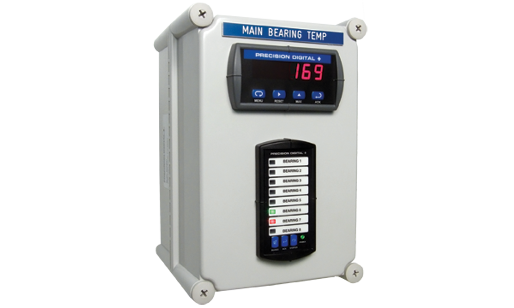
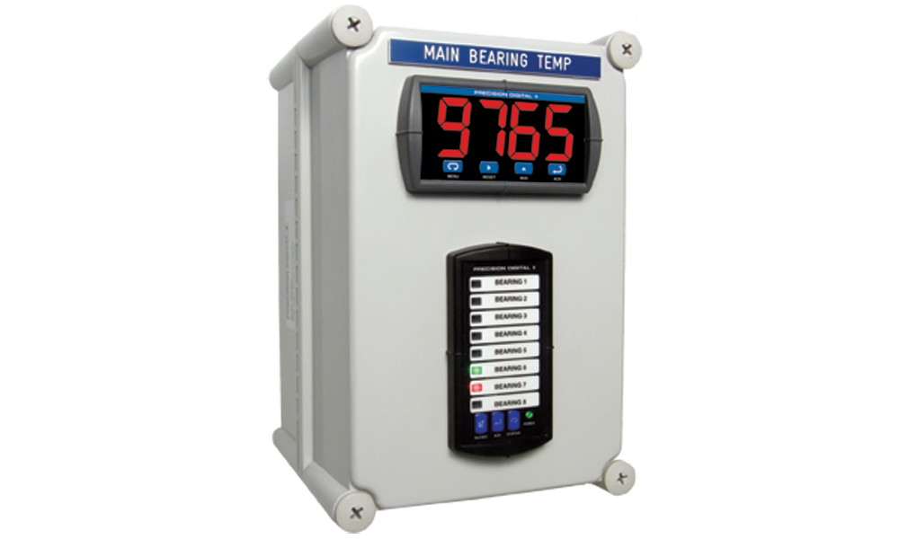
PD765 Trident Meter
Display: Trident: 0.56” (14.2 mm); Trident X2: 1.20” (30.5 mm) red LED, 4 digits (-1999 to 9999)
Display Intensity: Eight user selectable intensity levels
Front Panel: NEMA 4X, IP65; panel gasket provided
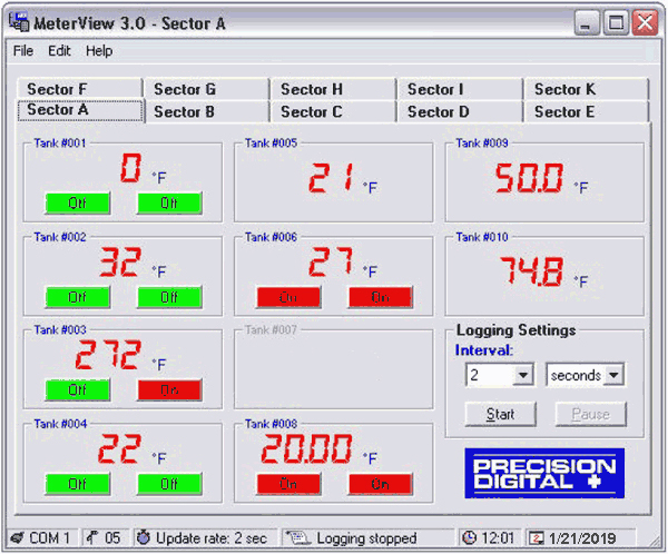
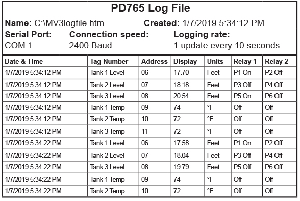
Programming Methods: Four front panel buttons, cloning with Copy feature, PC with MeterView or LabVIEW software, and Modbus registers. Certified LabVIEW driver available.
Noise Filter: Programmable 2 to 199 (0 will disable filter)
Display Update Rate: Process/RTD: 3.7-5/sec; TC: 1.8-2.5/sec
Overrange: Display flashes 9999
Underrange: Display flashes -1999
Recalibration: All inputs are calibrated at the factory; recalibration is recommended at least every 12 months.
Max/Min Display: Stored until reset by user or meter is turned off.
Password: Restricts modification of programmed settings.
Non-Volatile Memory: Settings stored for a minimum of 10 years.
Power: 85-265 VAC, 50/60 Hz; 90-265 VDC, 20 W max
Required Fuse: UL Recognized, 5 A max, slow-blow; up to 6 meters may share one fuse.
Normal Mode Rejection: 64 dB at 50/60 Hz
Isolation: 4 kV input/output-to-power line; 500 V input-to-output or output-to-24 VDC supplies.
-6R5 & -6X5 models only: 100 V output-to-24 VDC supply
Operating Temperature: -40 to 65°C
Storage Temperature: -40 to 85°C
Relative Humidity: 0 to 90% non-condensing
Connections: Power & Signal: removable screw terminal blocks accept 12 to 22 AWG.
Serial: RJ11 header, standard on all meters.
Enclosure: 1/8 DIN, high impact plastic, 94V-0, color; gray
Weight: 9.5 oz (269 g) (including options)
UL File Number: E160849; 508 Industrial Control Equipment
Warranty: 3 years parts & labor
Process Inputs
Inputs: Field selectable: 0-20 mA, 4-20 mA, 1-5 V, ±10 V
Accuracy: ±0.05% FS ±1 count; square root: ±0.1% FS ±2 counts
Function: Linear or square root
Low-Flow Cutoff: 0 to 9999 (0 disables cutoff function)
Decimal Point: Up to 3 decimals: d.ddd, dd.dd, ddd.d, or dddd
Calibration: Scale without signal or calibrate with signal source
Calibration Range: User programmable over entire range of meter
Input Impedance: Voltage range: greater than 1 M Ω, Current Range: 50-100 Ω, varies with resettable fuse impedance
Input Overload: Protected by automatically resettable fuse
Temperature Drift:| 0 to 65°C ambient | -40 to 0°C ambient |
| Current: ±0.20% FS (50 PPM/°C) | Current: ±0.80% FS |
| Voltage: ±0.02% FS (1.7 PPM/°C) | Voltage: ±0.06% FS |
Transmitter Supply: Isolated, one or two transmitter supplies
P1: 24 VDC ±10% @ 200 mA max (-1 option)
P1 & P2: 24 VDC ±10% @ 200 mA & 40 mA max (-2 option)
Temperature Inputs
Inputs: Factory calibrated, field selectable: type J, K, T, or E thermocouples and 100 Ω platinum RTD (0.00385 or 0.00392 curve)
Resolution: 1°; type T: 1° or 0.1°
Cold Junction Reference: Automatic
Temperature Drift: ±2°C maximum
Offset Adjustment: Programmable to ±19.9°. This parameter allows the user to apply an offset value to the temperature being displayed.
Input Impedance: Greater than 100 k Ω
Sensor Break: All relays and alarm status LEDs go to alarm state.
| Input Type | Range | Accuracy
(0-65° C) | Accuracy
(-40-0° C) |
| Type J | -58° to 1382° F
-50° to 750° C | ±2° F
±1° C | ±5° F
±3° C |
| Type K | -58° to 2300° F
-50° to 1260° C | ±2° F
±1° C | ±4° F
±2° C |
| Type T | -292° to 700° F
-180° to 371° C | ±2° F
±1° C | ±13° F
±7° C |
Type T
0.1° Res | -199.9° to 700.0° F
-180.0° to 371.0° C | ±1.8° F
±1° C | ±13° F
±7.2° C |
| Type E | -58° to 1578° F
-50° to 870° C | ±2° F
±1° C | ±11° F
±6° C |
| 100 Ω RTD | -328° to 1382° F
-200° to 750° C | ±1°F
±1° C | ±5°F
±3° C |
Relays
Rating: 2 Form C (SPDT); rated 3 A @ 30 VDC or 3 A @ 250 VAC resistive load; 1/14 HP @ 125/250 VAC inductive loads
Deadband: 0-100% FS, user selectable
High or Low Alarm: User may program any alarm for high or low
Relay Operation:- Automatic (non-latching)
- Latching
- Pump alternation control
Relay Reset: User selectable via front panel buttons or PC
- Automatic reset only (non-latching)
- Automatic plus manual reset at any time (non-latching)
- Manual reset only, at any time (latching)
- Manual reset only after alarm condition has cleared (latching).
Automatic Reset: Relays reset when input passes the reset point
Manual Reset: Front panel button, MeterView, Modbus registers
Time Delay: 0 to 199 seconds, on and off delays; programmable
Fail-Safe Operation: Programmable, independent for each relay. Relay coils are energized in non-alarm condition. In case of power failure; relays will go to alarm state.
Auto Initialization: When power is applied to the meter, relays will reflect the state of the input to the meter.
Isolated 4-20 mA Transmitter Output
Scaling Range: 1.00 to 23.00 mA; reverse scaling allowed.
Calibration: Factory calibrated 4.00 to 20.00 mA
Accuracy: ±0.1% FS ±0.004 mA
Temperature Drift: 50 PPM/°C
Note: Analog output drift is separate from input drift
Isolation: 500 V input-to-output or output-to-24 VDC supplies; 4 kV output-to-power line
External Power: 35 VDC maximum
Output Loop Resistance:| Loop Resistance |
| Power Supply | Minimum | Maximum |
| 24 VDC | 10 Ω | 700 Ω |
| 35 VDC (external) | 100 Ω | 1200 Ω |
Serial Communications
Compatibility: EIA-232, EIA-422, and EIA-485 with PDA7232 and PDA7422 Trident adapters.
Protocol: Two selectable. PDC protocol (for use with MeterView) and Modbus RTU
Meter Address: PDC protocol: 0 to 99, Modbus protocol: 1 to 247
Baud Rate: 300 to 19,200 bps
Transmit Time Delay: Programmable 0 to 199 ms or transmitter always on for RS-422 communications.
Data: 8 bit (1 start bit, 1 stop bit)
Parity: None (2 stop bits), even, or odd
(Modbus only; PDC protocol does not use parity)
Byte-to-Byte Timeout: 0.01 to 2.54 seconds (Modbus only)
Turn Around Delay: Less than 2 ms (fixed)
Refer to PDC and Modbus Serial Communications Protocol manuals for details.
Note: Both downloadable protocol register tables can be found in the documentation list below.
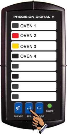
PD138 Scanner
Number Of Channels: 8 double-pole channels per unit
Number Of Channels Per System: Unlimited
Signals Switching: DPST reed relays
Contact Resistance: 0.2 Ω maximum
Maximum Input Voltage: 200 V (switched or common mode)
Maximum Current Switched: 0.5 A
Maximum Power Switched: 10 W
Dwell Time: Each channel adjustable from 0.6 to 30 seconds
Non-Volatile Memory: All programming values are stored in non-volatile memory for ten years if power is lost
Scan Method: Internal or manually controlled
Channel Indication: Green LED on front panel
Disabling Channels: Any channel may be disabled during setup
Scan Stop: The scan may be stopped by pressing and holding the STOP/GO button for more than 0.5 seconds. The scan may be resumed by pressing and releasing the STOP/GO button quickly (less than 0.5 seconds)
Alarm Input: Independent alarm input for each channel. Input Impedance; 25 K Ω, typical pull-up to 5 V
Alarm Sequence: Sequence A or Sequence F2A (first out)
Alarm Outputs: Alarm condition indicated by:
- Front panel red LED for each channel
- Relay, 1 SPDT (form C); rated 2 Amp @ 30 VDC or 2 Amp 2. @ 250 VAC resistive load; 1/14 HP @ 125 /250 VAC for inductive loads. For fail-safe operation, the relay is energized in the non-alarm state. In the case of a power failure, the relay will go to the alarm state, (NC contact is connected to common)
- Built-in Horn, 85 dB
- Stop-on-alarmed-channel (user select)
Alarm Acknowledge: Front panel ACK and rear connector terminals
External Switch Functions: The functions of the front panel buttons are available at screw terminals at the rear of the instrument
Message Labels: Free, custom printed, 2 lines per message at 14 characters per line. Factory or field printable. See manual for details
Connections: Removable screw terminal connectors provided:
Power + Relay: 22 to 12 AWG; Alarm Input, Analog Signal, External Switches, I/O: 30 to 16 AWG
Operating Temperature: -40°C to 65°C
Storage Temperature: -40°C to 85°C
Relative Humidity: 0 to 95% non-condensing
Power: 115 VAC, ±10%, 50/60 Hz, 22 W max
Led Test: All LEDs are tested on power-up
Enclosure: 1/8 DIN, high impact plastic, UL94V-0
Front Panel: NEMA 4X, panel gasket provided
Warranty: 3 years parts & labor
PDA2821 Enclosure
Dimensions: 11" x 7.5" x 7.1" (190mm x 280mm x 180mm)
Material: Plastic
Color: Gray
Ratings: NEMA 4X (PDA2801: NEMA 4)