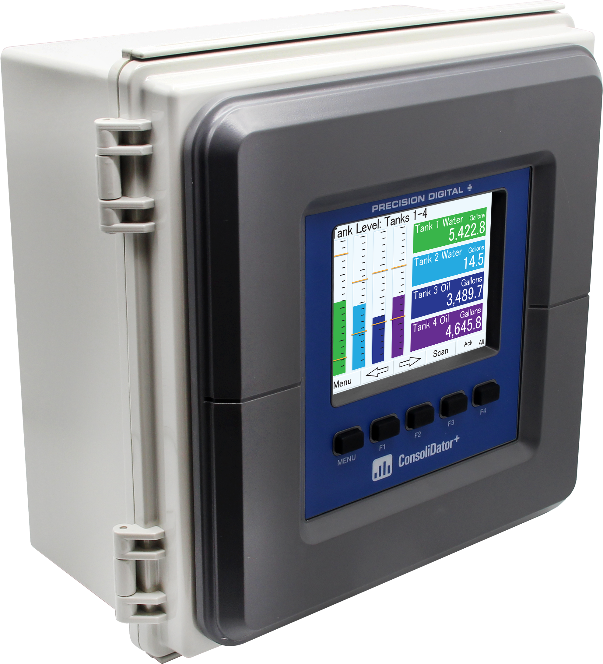
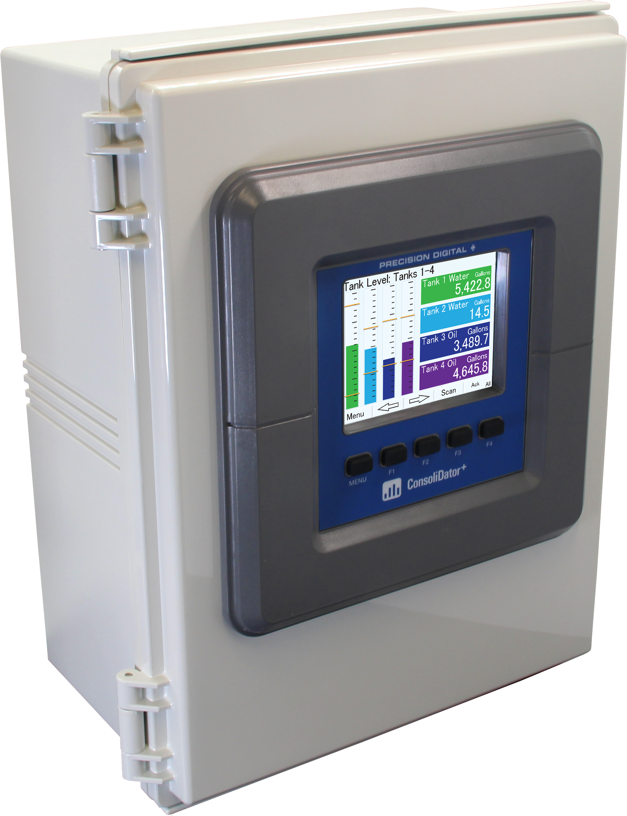
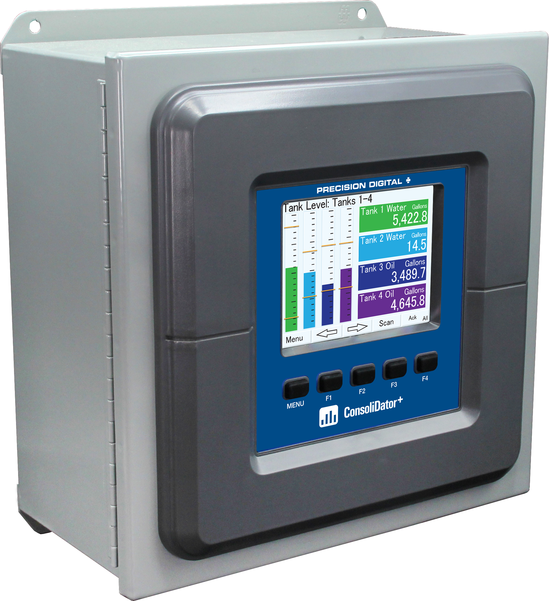
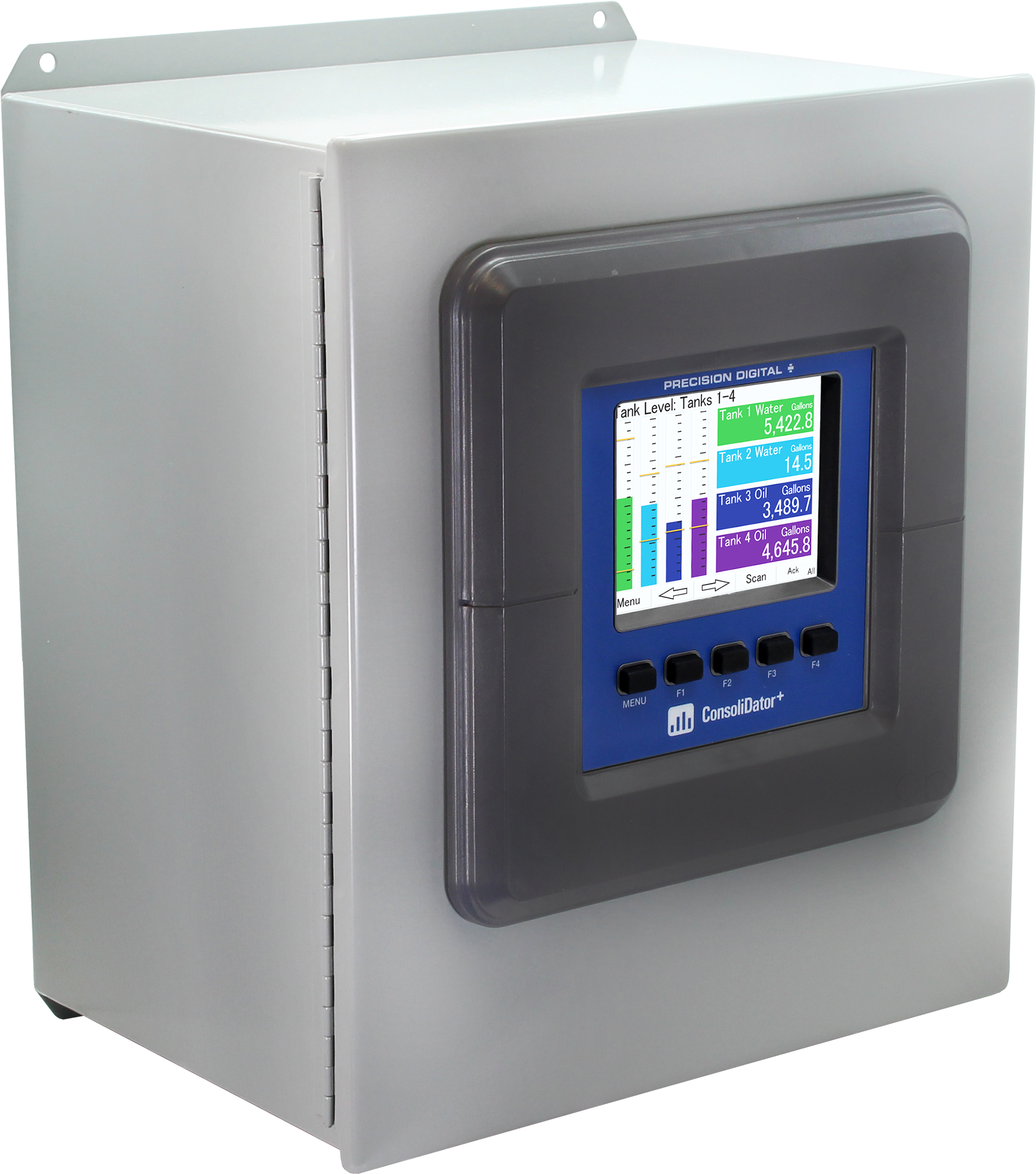
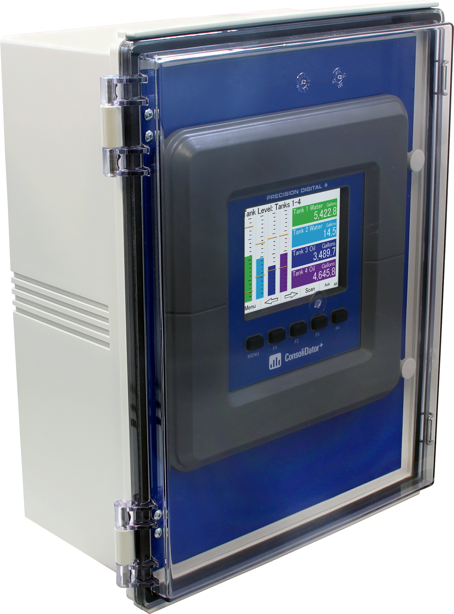
- NEMA 4X Panel Mount Multivariable Controller
- Convenient Display, Control, & Alarm of Multiple 4-20 mA, Temperature, Pulse, & Modbus Inputs
- Numeric & Bargraph Color Display (320 x 240 pixels) 5.7" (145 mm)
- Sunlight Readable Display, White Backlight; UL/C-UL Listed Sun Hood Option Available
- Isolated 24 VDC Transmitter Supplies 200 mA / Analog Input: 1,600 mA Max
- 99 Channels, 32 Totalizers, 30 Timers, & 199 Modbus Inputs
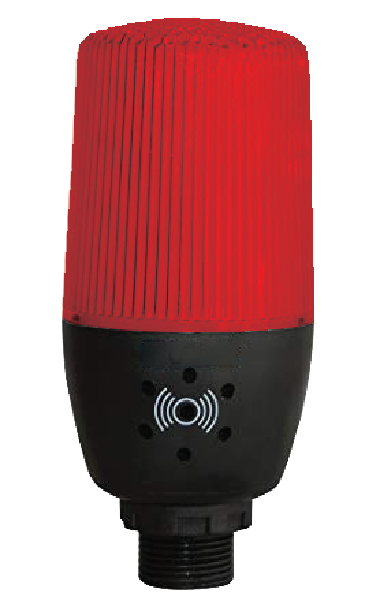
- 64 High & Low Alarms, Combine Multiple Alarms Into Logic AND & OR Alarms
- Simulation & Manual Control Modes for Testing and Setup
- Modular Design for Inputs & Outputs Flexibility
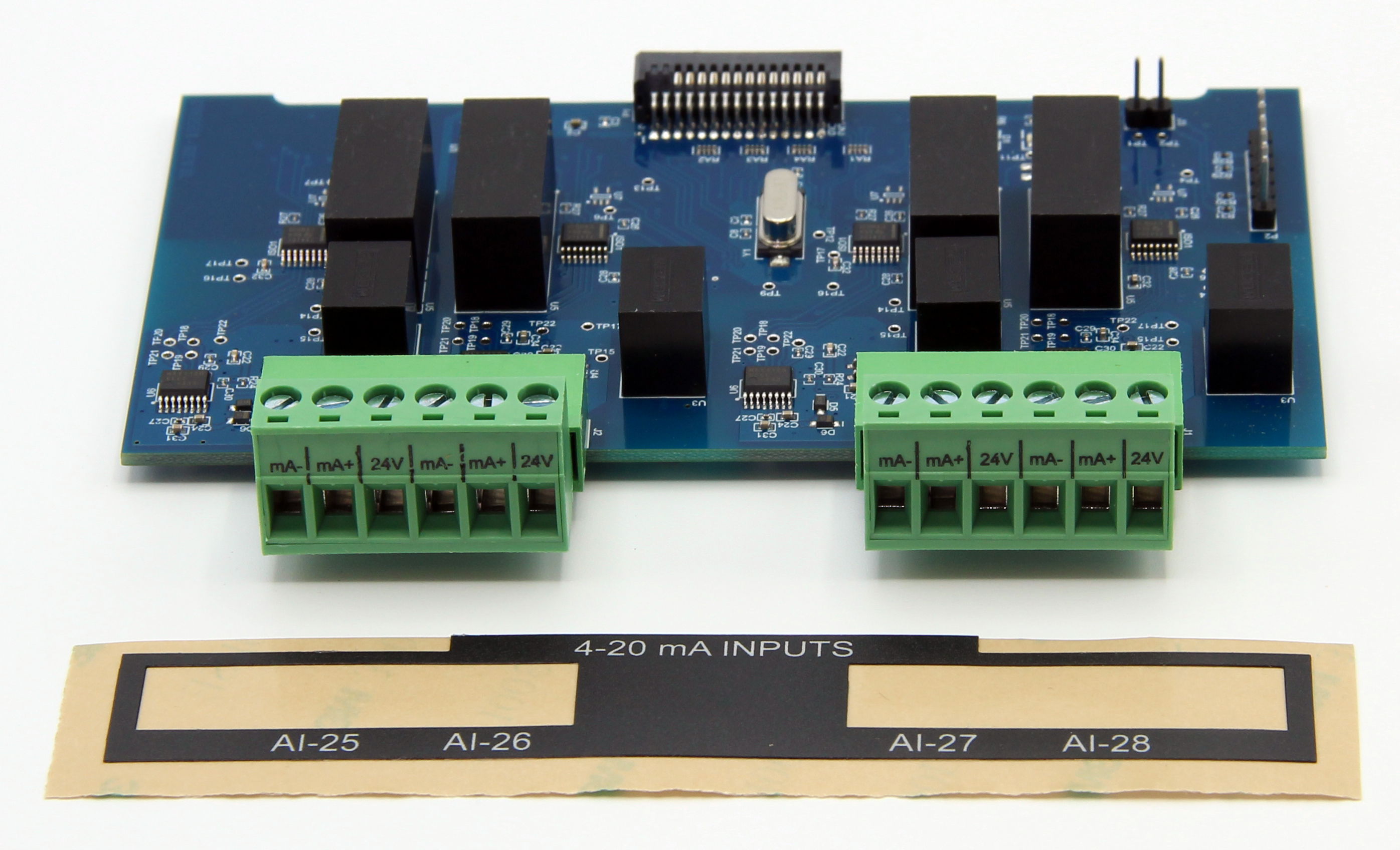
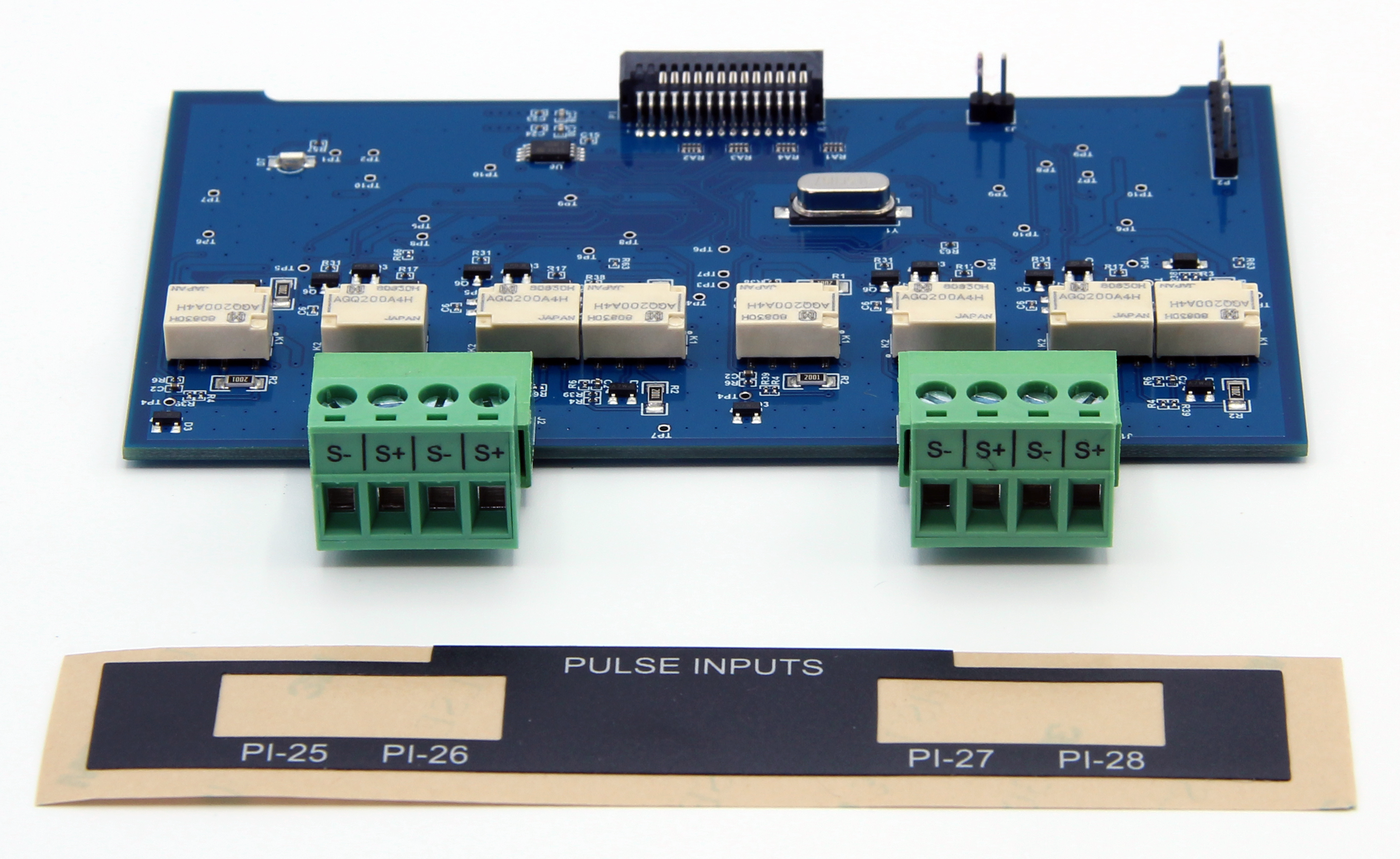
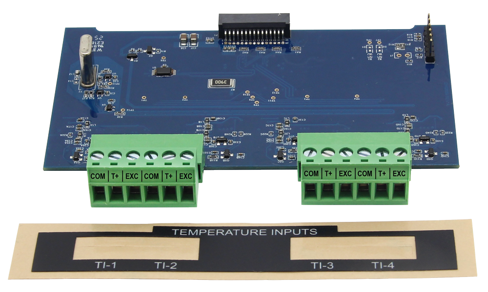
- Up to (28) Inputs; Isolated 4-20 mA, Pulse, or Temperature (Thermocouple or RTD)
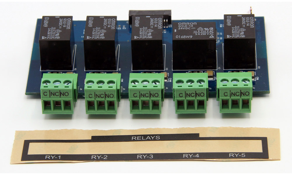
- Up to (25) 10 Amp Form C Relays (With Eight Analog or Pulse Inputs)
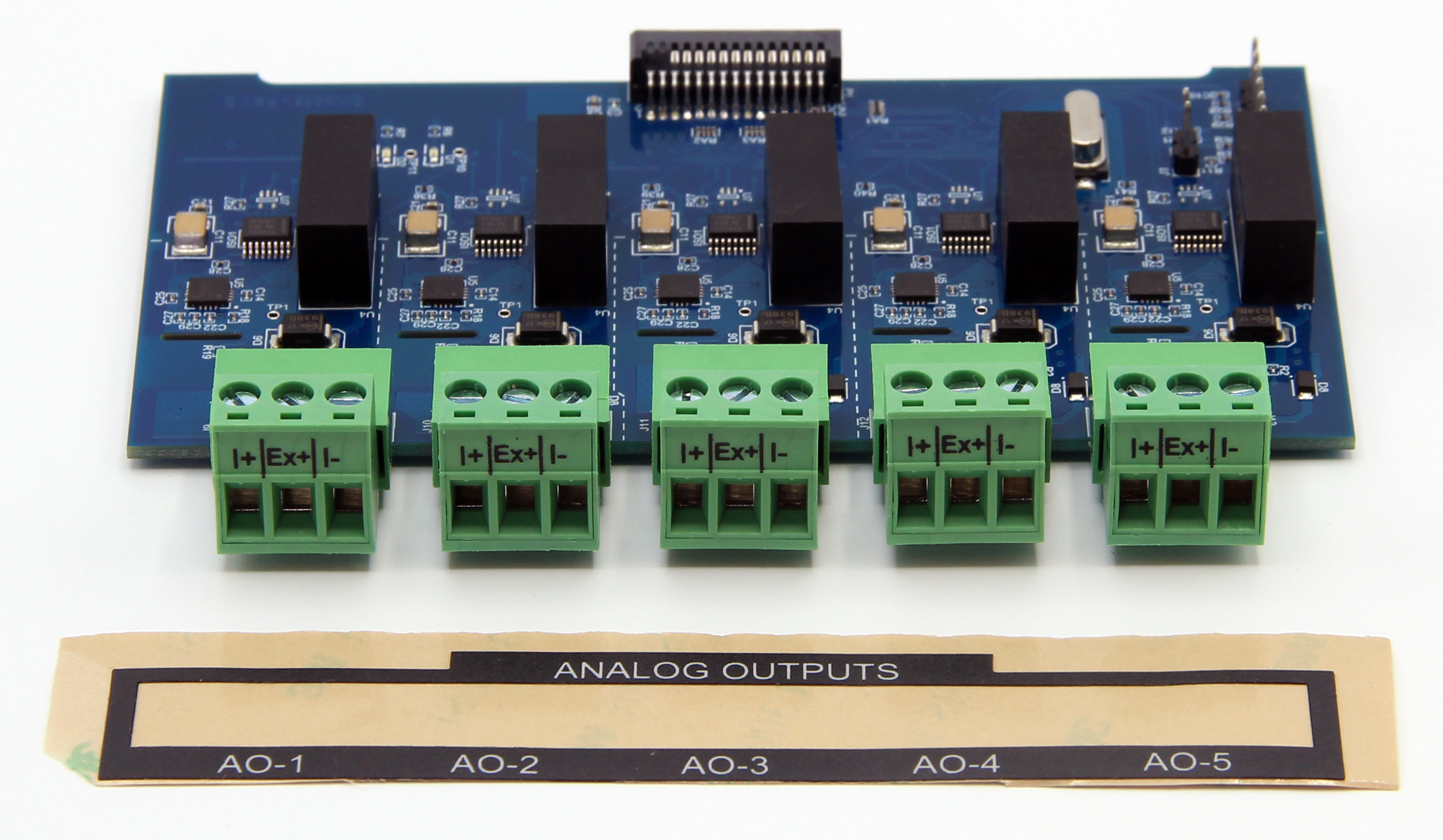
- Up to (25) Isolated 4-20 mA Outputs (With Eight Analog or Pulse Inputs)
- Operating Temperature Range: -25°C to 55°C (-13 to 131°F)
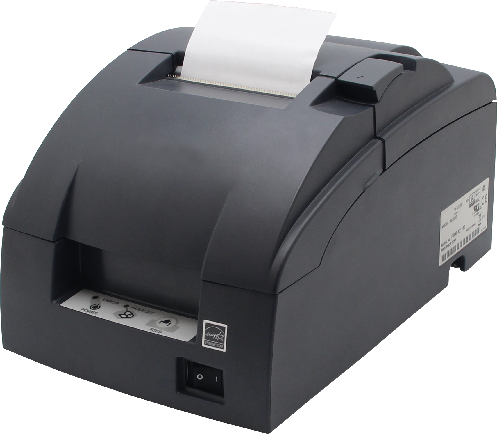
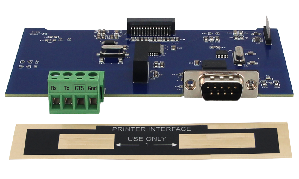
- Print Critical Data from ConsoliDator+ with Printer Card
- Pulse, Analog, & Modbus Input Flow Rate / Total / Grand Total Capability
- 50-Point Linearization, Square Root, and Exponent for Open Channel Flow
- Round Horizontal Tank Volume Calculation; Just Enter Diameter & Length
- Open Channel Flow Math Formulas for Weirs & Flumes
- Multi-Pump Alternation with On-Off Multi-Setpoint Control and Lead-Lag Control
- HOA Switch Controls Pump Relays for Auto, Manual, or On/Off Modes
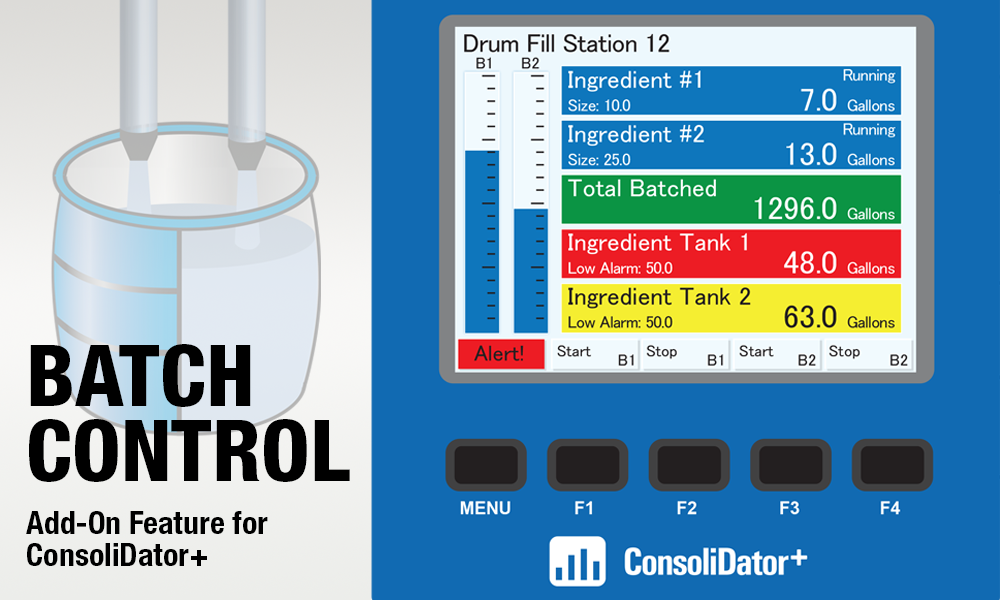
- Advanced Batch Control Features with Ticket Printing Capabilities
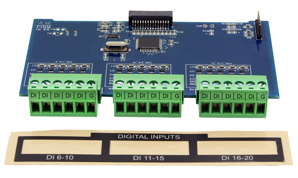
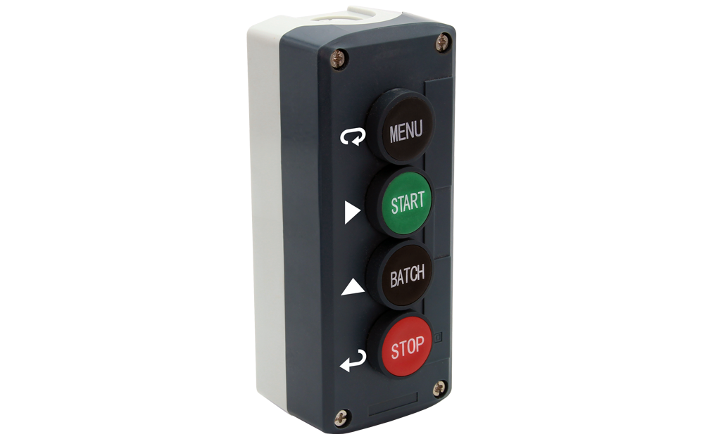
- Programmable Displays, Function Keys & Digital Inputs (Five Standard) and Optional 15-Digital Inputs Card Available
- Math Functions: Sum, Diff, Average, Multiply, Divide, % Efficiency, & More
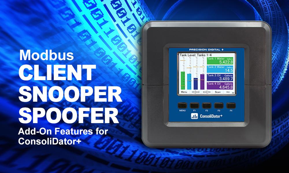
- Modbus Client (Master) & Snooper / Server with 99 Programmable Outputs
- Direct Modbus PV Inputs – Snooper / Server Mode
- RS-485 Serial Communication with Modbus RTU / ASCII & Ethernet TCP/IP
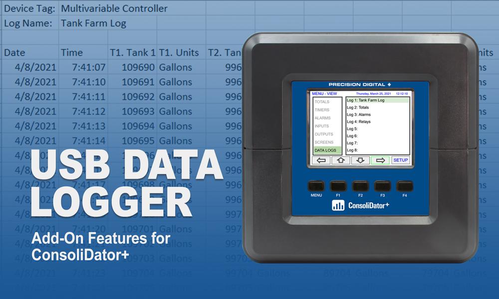
- USB Data Logger Feature: Up to 8 Log Files with up to 12 Parameters Each
- Input Power Options: 90-264 VAC or 24 VDC
- (20) Screens with up to Eight PVs Each
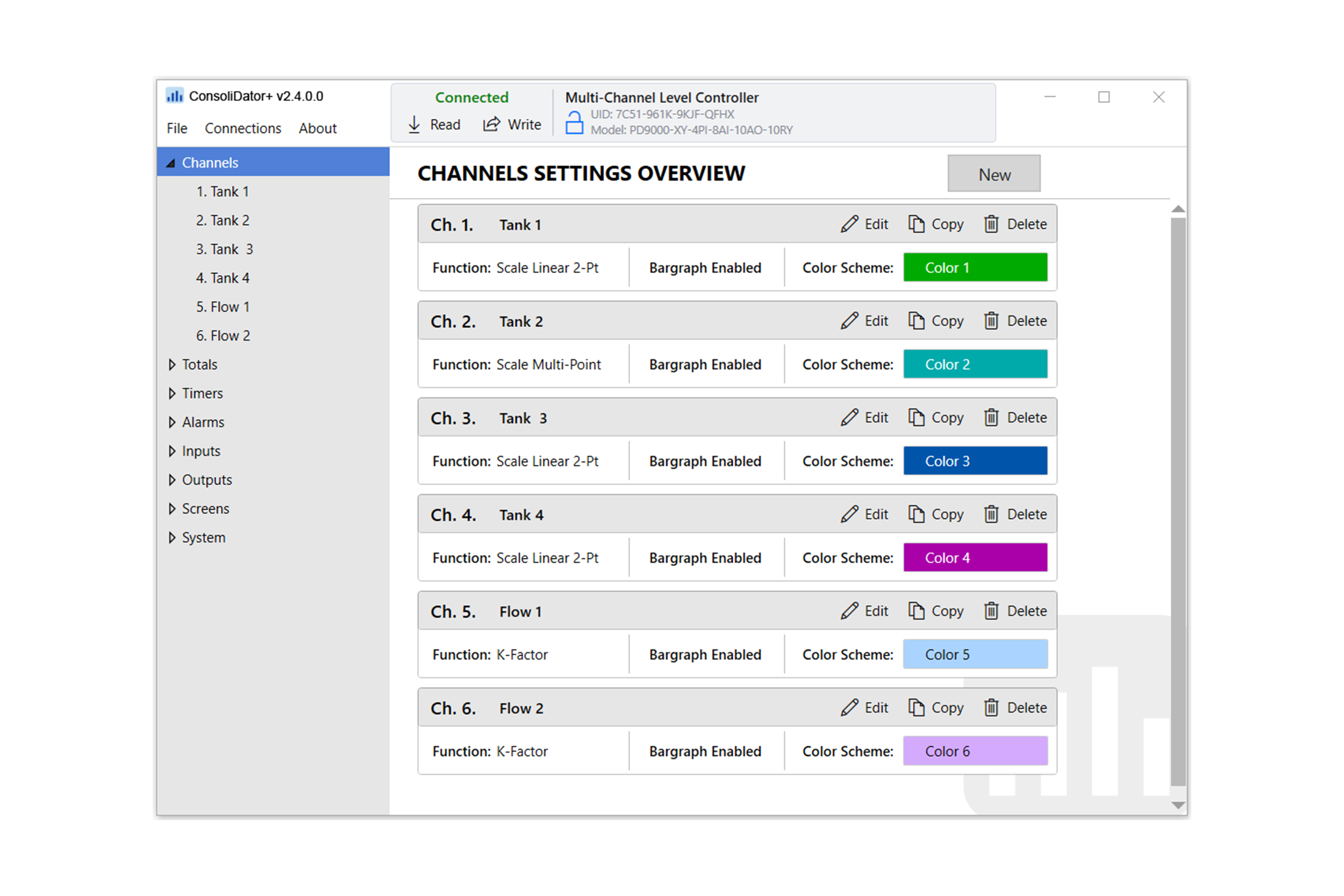
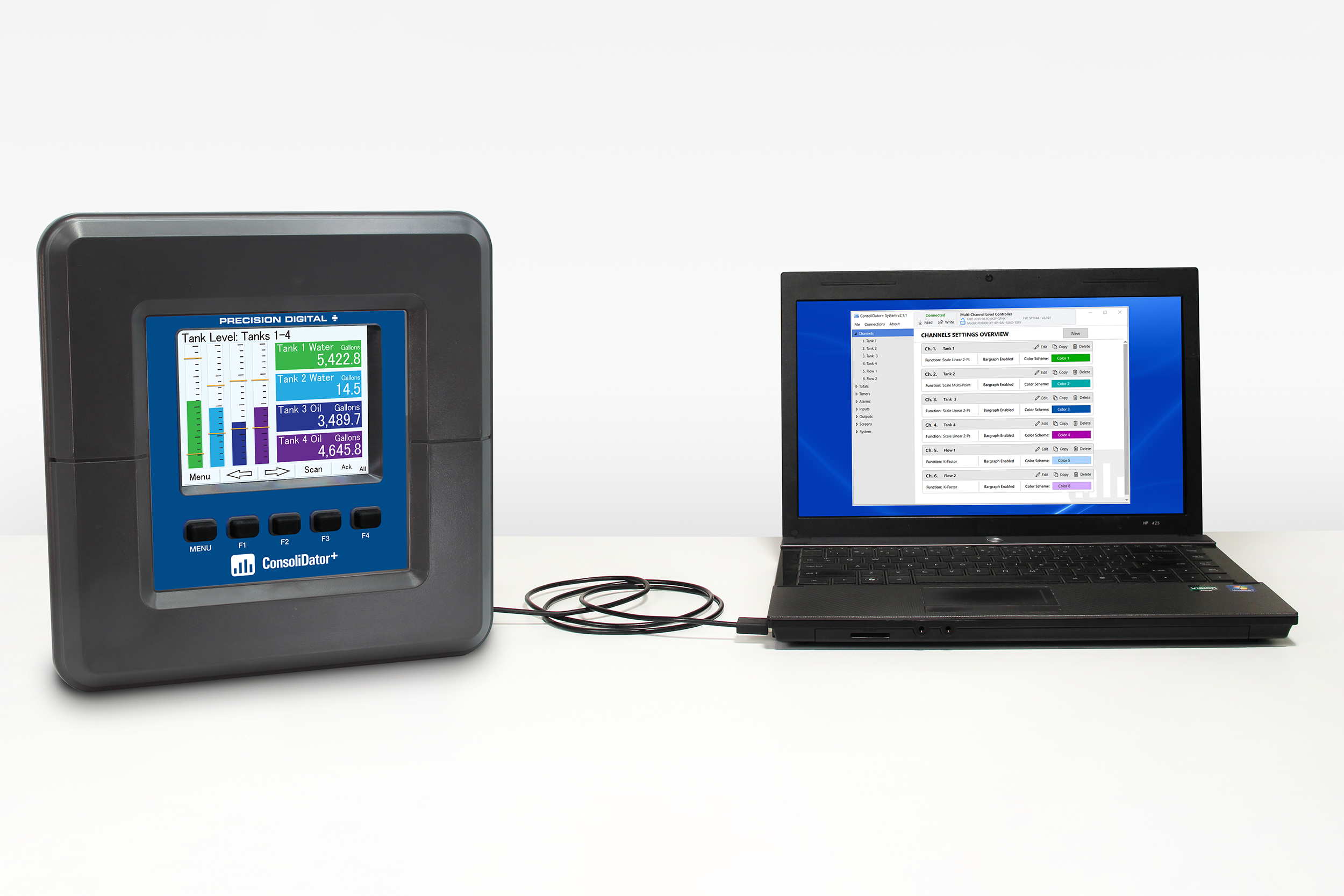
- ConsoliDator+ Configuration Software
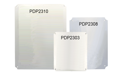
- Type 4X, IP66 Front – Field Enclosures Available
- Auto-Tune PID Control for Multiple Control Loops with Analog, Digital, or Relay Outputs
- 3-Year Warranty
** NEW IMPROVED WEB STORE! | All users must register for a new account. | Register now > **
BUY ONLINE TO SAVE TIME AND INCREASE ORDER ACCURACY!

Questions? (508) 655-7300
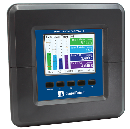
ConsoliDator+ Multivariable Controller
PD9000


Models in stock
from $1990.00
The ConsoliDator+ is a multivariable controller that is both easy to use and satisfies a wide variety of process display, alarm, and control applications. It accepts 4-20 mA inputs, flow meter pulse inputs, digital inputs, and Modbus inputs and displays them in both numeric and bargraph format on a large, 5.7" color display.
It can be equipped with multiple relays with user-definable actions, 4-20 mA outputs, digital outputs, Modbus RTU & ASCII, Modbus Enron, and Ethernet Modbus TCP/ IP protocol communication. Additionally, the controller is equipped with up to 30 timers that can be used to control many processes or events.
New features that have been added to the ConsoliDator+ include:
• Auto-Tune PID Control
• Digital Switches (HOA)
• Advanced Batch Control Features
• Print batch tickets, process variables, and other critical data
• Pump Alternation with On-Off Multi-Setpoint and Lead-Lag Control
All this functionality is easily programmed using the free software or via the front panel pushbuttons. Choose the model that best suits your application, from monitoring only to fully loaded controllers with an extensive combination of inputs, outputs, and communication protocols.
Why Should You Buy:
- Display Multiple Inputs on One Screen
- 4-20 mA & Pulse Inputs
- Relay & 4-20 mA Outputs
- Batch Control
- Pump Control
- Power the Transmitters
- Ethernet Modbus TCP/IP Option