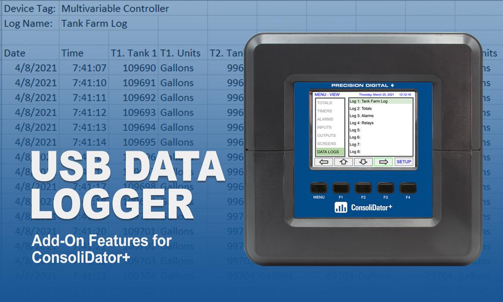

The PD9000 ConsoliDator+ Data Logger Add-On Feature allows you to log data to an external USB flash drive and create logs that contain the same type of process data or a mix of just about anything you might want to log. Each log can contain up to 12 process variables, inputs, outputs, timers, alarm status, relay status or a combination of parameters such as mA inputs, digital inputs, Modbus inputs, channels, totals, timers, and more. The data logger can be controlled in many ways; the start/stop, enable switch, log trigger, or log interval. See the PD9000 instruction manual for more details.
Add-On features that are ordered with the ConsoliDator+ will be activated at the factory. Add-On features can be ordered for existing ConsoliDator+ units with a firmware version of 2.2 or greater, at any time. The user will receive a key they can enter into the ConsoliDator+ to unlock the Add-On feature.
Setup Data Log
The Setup Data Logs menu is used to configure settings that are used for logging data to an external USB flash drive. Any data parameter can be logged; up to 8 data logs can be created. Each data log can contain from 1 to 12 parameters.
Setup New Data Log

The setup of the data logs is easy, intuitive, and flexible. You can create logs that contain the same type of process data or you can have a mixed of just about anything you might want to log.
- Navigate to the Data Logs menu
- Press the New key (F4) to create a new log
- An untitled log is created

| Log #: | Enter log file name |
| Add: | Add items to be logged |
| Start / stop: | Control the log start & stop |
| Enable switch: | Select an additional log control |
| Log trigger: | Trigger log on a specific event |
| Log interval: | Log at the specified interval |
| Log with units: | Each log entry will have the corresponding engineering units |
 Do not change the units for totals, while the data logger is running; the accumulated total will not be converted to the new units and the reflected value will not be accurate.
Add Items to Be Logged
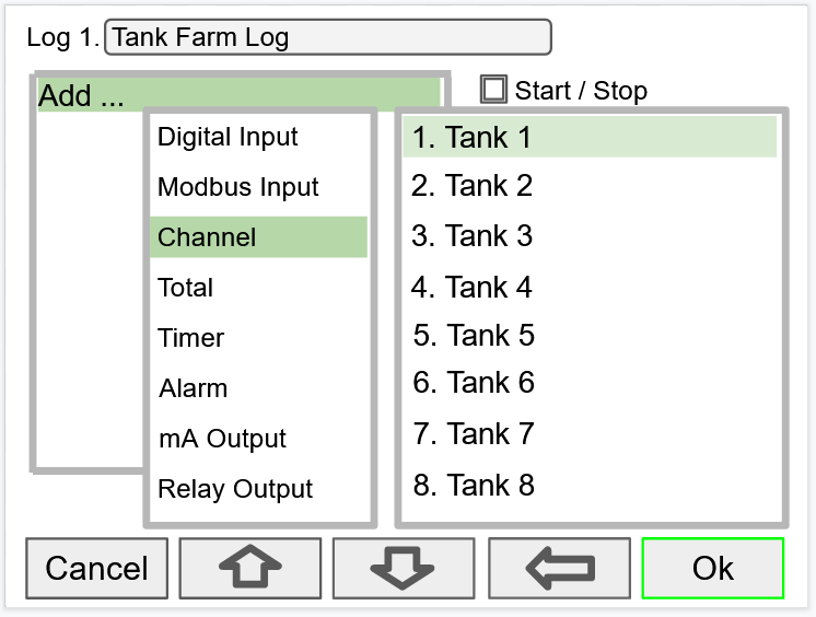
Each log can contain up to 12 process variables, inputs, outputs, timers, alarm status, relay status, or a combination of any of the following parameters:
1. mA Inputs
2. Digital Inputs
3. Modbus Inputs
4. Channels
5. Totals
6. Timers
2. Digital Inputs
3. Modbus Inputs
4. Channels
5. Totals
6. Timers
7. Alarms
8. mA Outputs
9. Relay Outputs
10. Digital Outputs
11. Modbus Outputs
8. mA Outputs
9. Relay Outputs
10. Digital Outputs
11. Modbus Outputs
Setup Log Start / Stop

The log Start / Stop is used to give the system or the operator control to start and stop the log process.
The Start / Stop function is available in the View Log menu via the function keys.
The Start / Stop function can be activated with:
The Start / Stop function is available in the View Log menu via the function keys.
The Start / Stop function can be activated with:
- Screen F1-F4 function keys
- Digital inputs
- Modbus inputs
- Modbus outputs
- Channel Control: Schedule, Sampler
Setup Log Enable Switch

The log Enable Switch can be any item with a binary value (on / off, 0 / 1, true / false). Log entries will be made only if the Enable Switch is in the on position.
The Enable Switch input can be:
The Enable Switch input can be:
- Digital input
- Modbus input
- Channel
- Alarm
- Relay Output
Setup Log Trigger
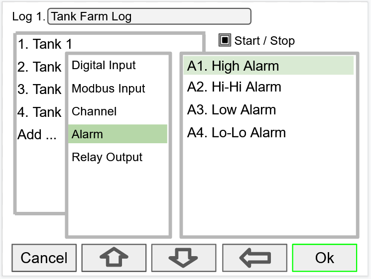
The Log Trigger can be any event from the list below. Log entries will be made every time the input is activated.
The Log Trigger input can be:
The Log Trigger input can be:
- Digital input
- Modbus input
- Channel
- Alarm
- Relay Output
Setup Log Interval & Log Units
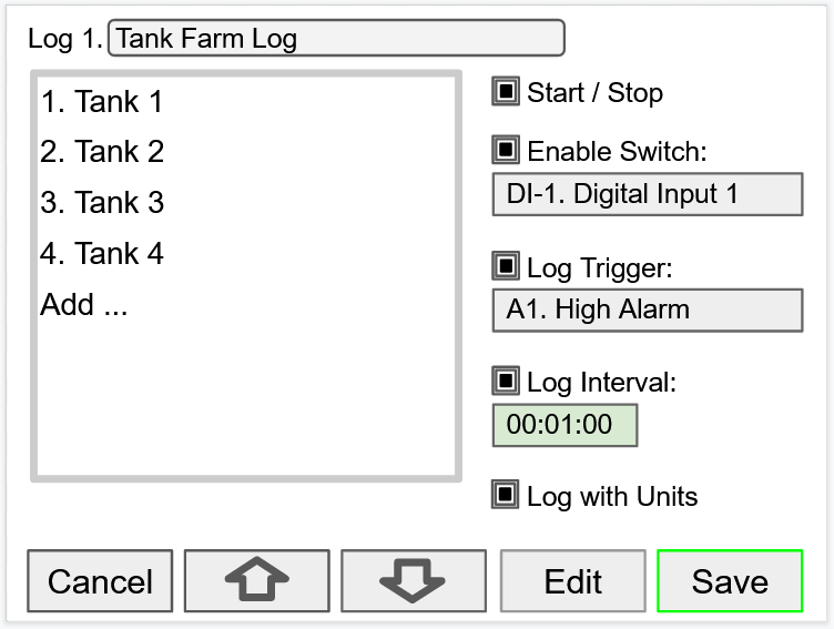
The Log Interval can be from 1 sec to 99:59:59 hh:mm:ss. Log entries will be made at the selected interval.
In this example the log must be started, and the digital input 1 must be on to log the tanks volume every minute.
To log continuously without the need to start or enable the log, deselect the Start / Stop and the Enable Switch settings.
If engineering units are not needed, deselect the Log with Units setting.
If Start / Stop is enabled, the log will stop on a power cycle. Make sure to monitor if the power is turned off and re-start the log when the power is turned on.
In this example the log must be started, and the digital input 1 must be on to log the tanks volume every minute.
To log continuously without the need to start or enable the log, deselect the Start / Stop and the Enable Switch settings.
If engineering units are not needed, deselect the Log with Units setting.
Setup USB Drive
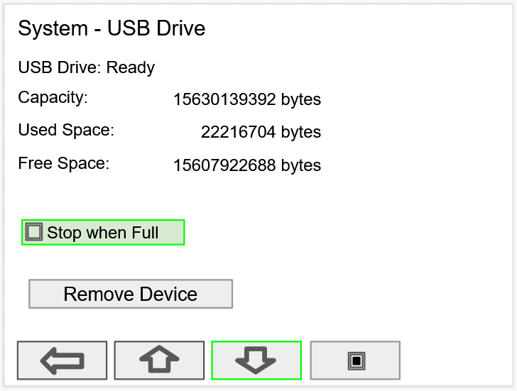
The System – USB Drive provides status information about the connected flash drive.
If Stop when Full is not selected, the oldest block of data will be deleted to make room for new data.
 The USB Drive menu is available only through the front panel.
- USB Drive Status
- Capacity
- Used Space
- Free Space
If Stop when Full is not selected, the oldest block of data will be deleted to make room for new data.
Safely Remove Flash Drive
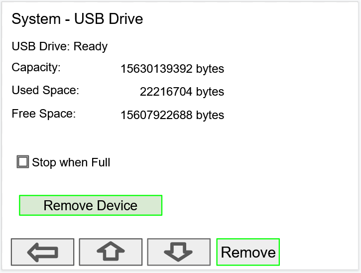
To safely remove the flash drive:
Go to the System – USB Drive screen, navigate to the Remove Device button using the down arrow key, then press the Remove key.
This procedure allows the USB drive to finish writing any log data in progress and prevent the lost or corruption of data.
Go to the System – USB Drive screen, navigate to the Remove Device button using the down arrow key, then press the Remove key.
This procedure allows the USB drive to finish writing any log data in progress and prevent the lost or corruption of data.
View Data Logs
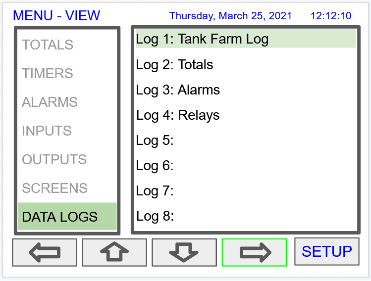
In the View Data Logs menu you can see a list of the active data logs. Press the right arrow key to go to the log list and to see details of any of the logs.
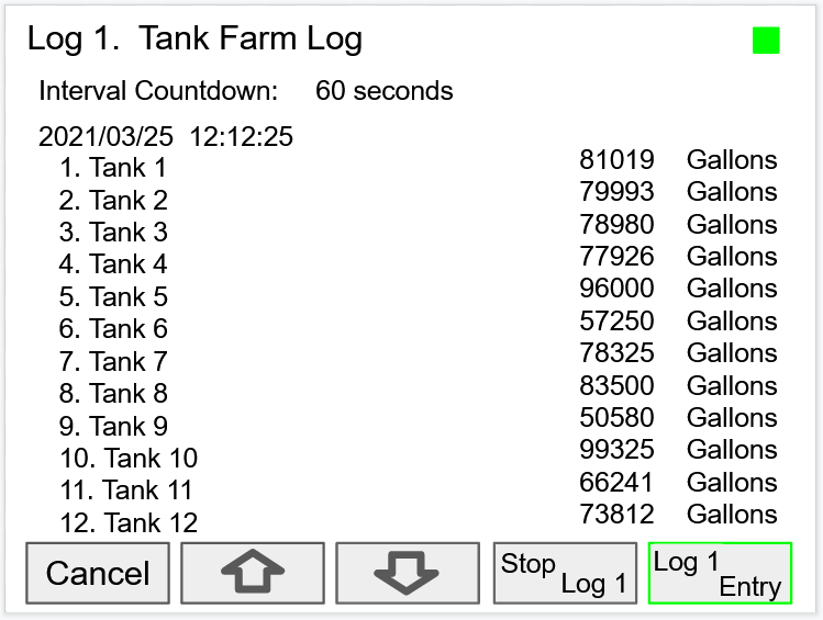
The screen shows a snapshot of the log in progress. If the log is not running, the screen will only show the log # and name. Press Start Log followed by Log Entry to capture the first log.
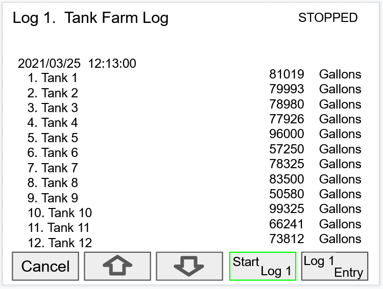
Press the Stop Log key to stop logging the selected log.
The Start / Stop function can be enabled or disabled during the log setup. This function is independent for each log.
After the log is started, the system will capture the first log according to the log setup selected.
The Log Entry key allows the user to capture a snapshot of the process any time.
There is no provision for viewing previous log records on the screen. The flash drive must be removed and connected to a computer to download the saved logs.


