- Fully Approved Explosion-Proof Temperature Meter
- J, K, T, E, R, S, B, N, C Thermocouples
- 100 or 1000 Ω Platinum, 10 Ω Copper, 120 Ω Nickel RTDs
- 1° or 0.1° Resolution
- User Programmable Display in Fahrenheit or Celsius
- Capture Maximum and Minimum Temperature Readings
- Optional Isolated 4-20 mA Output Turns the Meter into a Temperature Transmitter
- Averages up to 10 RTD Sensors
- Automatic Cold Junction Compensation
- Dual-Line 6-Digit Display, 0.6" (15 mm) & 0.46" (12 mm)
- CapTouch Through-Glass Button Programming
- 4 Relays with Interlocking Capability + Isolated 4-20 mA Output Option
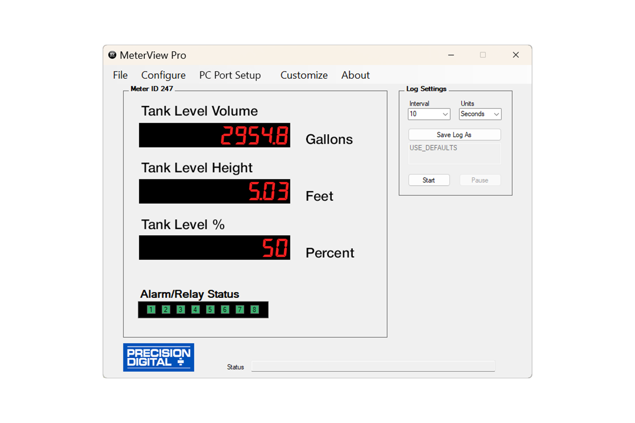
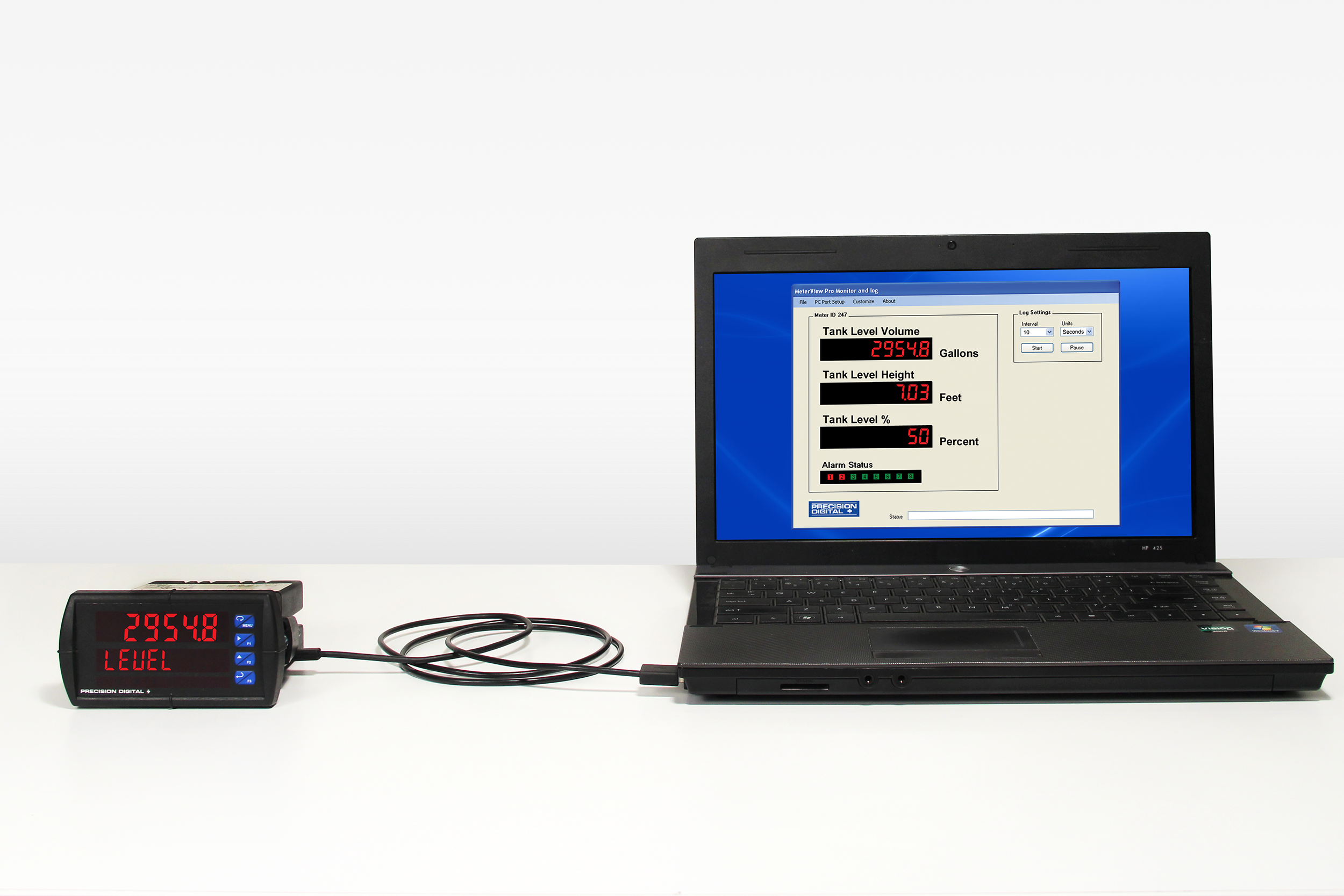
- Free PC-Based, On-Board, MeterView Pro USB Programming Software
- SunBright Display Standard Feature; Great for Outdoor Applications
- Operating Temperature Range: -55 to 65°C (-67 to 149°F)
- CSA Certified as Explosion-Proof / Dust-Ignition-Proof / Flame-Proof
- ATEX and IECEx Certified as Dust-Ignition-Proof / Flame-Proof
- Input Power Options: 85-265 VAC / 90-265 VDC or 12-24 VDC / 12-24 VAC
- Programmable Display, Function Keys & Digital Inputs
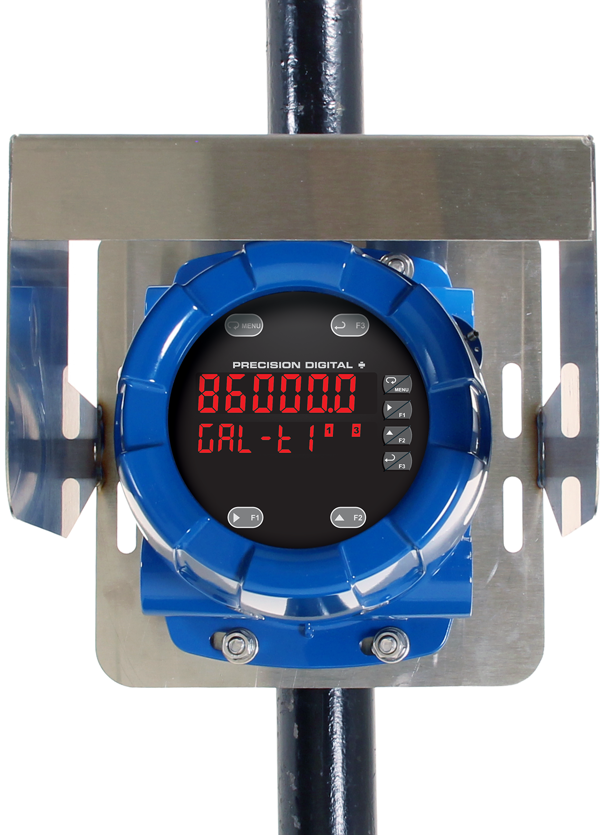
- Flanges for Wall or Pipe Mounting
- Explosion-Proof Aluminum or Stainless Steel NEMA 4X / IP68 Enclosures
- On-Board RS-485 Serial Communications
- Modbus RTU Communication Protocol Standard
- Password Protection
- Four 3/4" NPT Threaded Conduit Openings
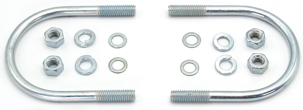
- Stainless Steel Pipe Mounting Kit
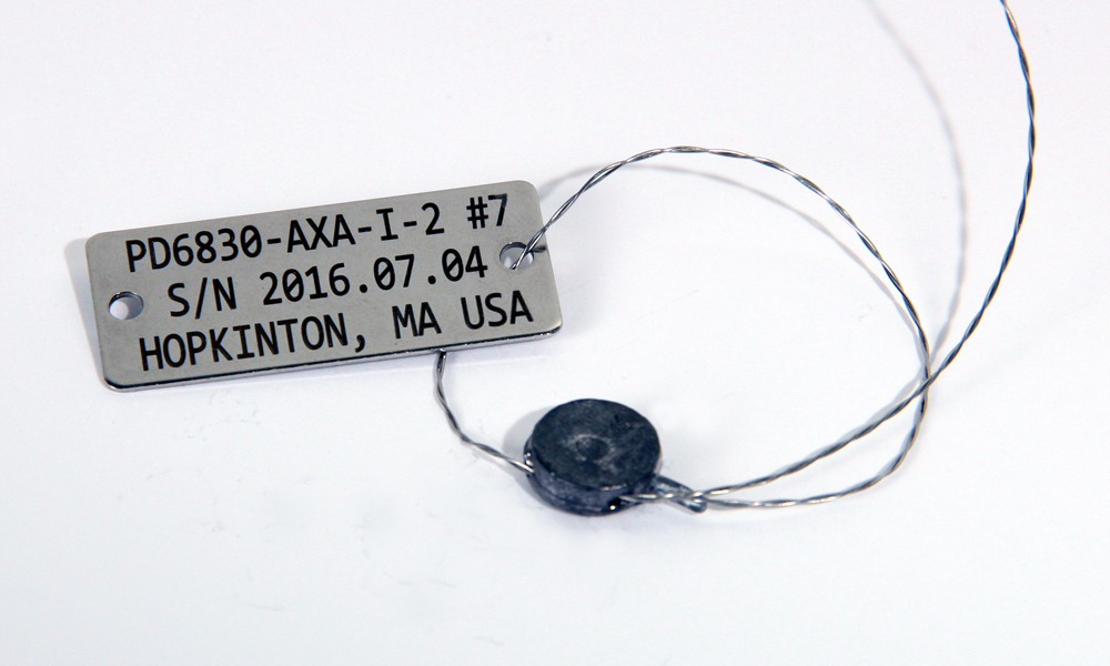
- Stainless Steel Tag Available
- 3-Year Warranty
** NEW IMPROVED WEB STORE! | All users must register for a new account. | Register now > **
BUY ONLINE TO SAVE TIME AND INCREASE ORDER ACCURACY!

Questions? (508) 655-7300
ProtEX-MAX Explosion-Proof Temperature Meter
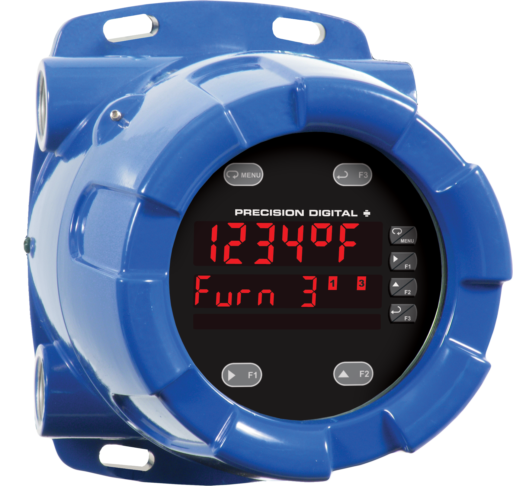
PD8-7000 in Aluminum Enclosure


Models in stock
from $1598.00
The ProtEX-MAX PD8-7000 offers all the functionality of the ProVu PD7000 as a CSA, ATEX, and IECEx certified explosion-proof product. It is available in an aluminum or stainless steel enclosure and will operate over a wide temperature range of -55 to 65°C (-67 to 149°F). It accepts a direct temperature input from a wide range of temperature measurement devices (type J, K, T, E, R, S, B, N, and C thermocouples and 100 or 1000 Ω platinum, 10 Ω copper, 120 Ω nickel RTDs). It displays the measured temperature in either degrees Fahrenheit or degrees Celsius on a dual-line, 6-digit Sunbright sunlight readable display. The meter includes automatic cold junction compensation for thermocouples and the ability to average up to ten (10) RTD sensors. The PD8-7000 can be equipped with four internal relays and a 4-20 mA analog output. It can be programmed and operated without opening the housing by using the built-in CapTouch through-glass buttons or the RS-485 serial communication port with free Modbus protocol.
Why Should You Buy:
- Worldwide Explosion-Proof Approvals
- Thermocouple or RTD Input
- Dual Line Display