- Fully Approved Explosion-Proof Pulse Input Flow Rate/Totalizers
- Pulse, Open Collector, NPN, PNP, TTL, Switch Contact, Sine Wave (Coil), Square Wave Inputs
- Dual-Line 6-Digit Display, 0.6" (15 mm) & 0.46" (12 mm)
- CapTouch Through-Glass Button Programming
- Display Mountable at 0°, 90°, 180°, & 270°
- Isolated 5, 10 or 24 VDC Flowmeter Power Supply
- Gate Function for Rate Display of Slow Pulse Rates
- 4 Relays with Interlocking Capability + Isolated 4-20 mA Output Option
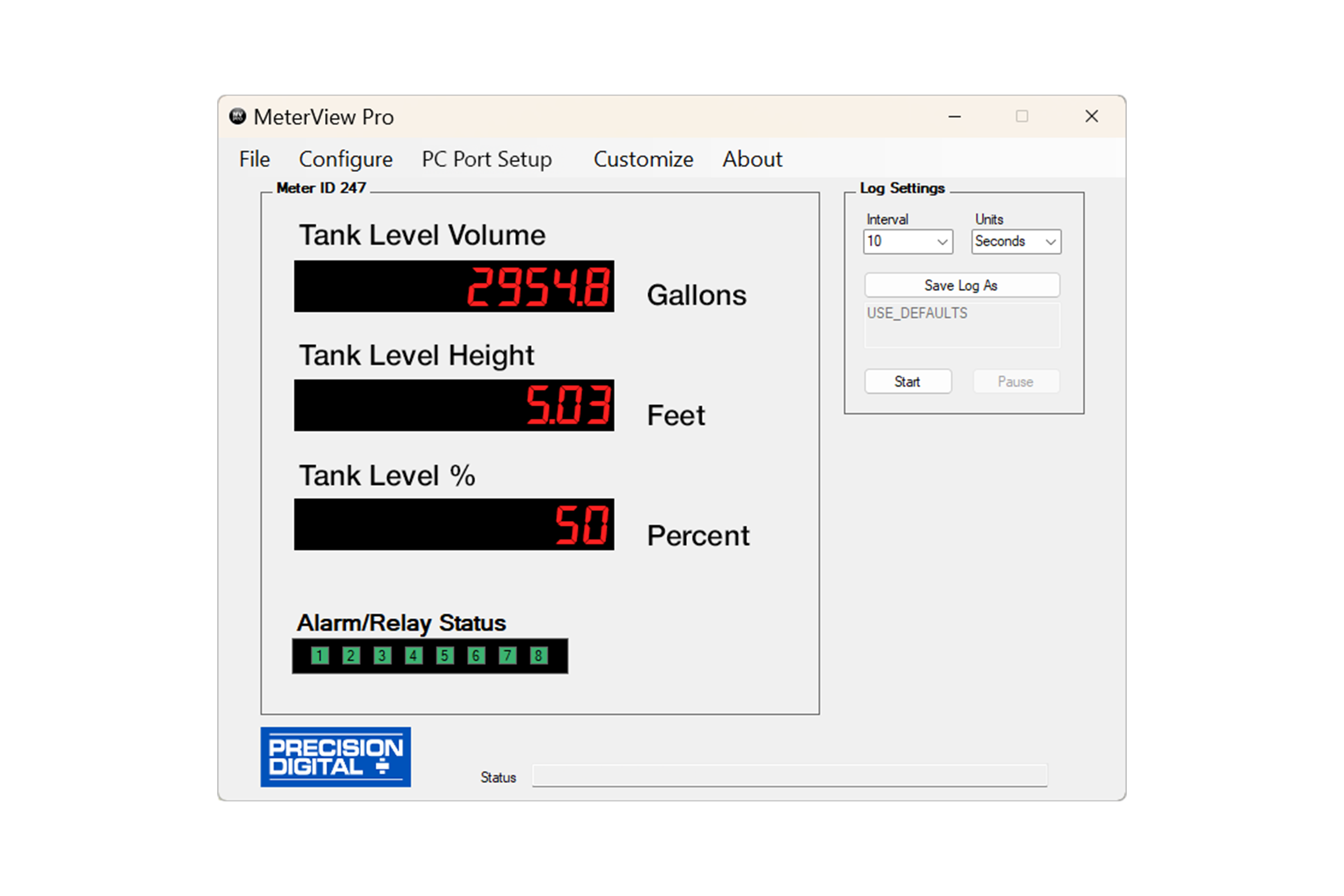
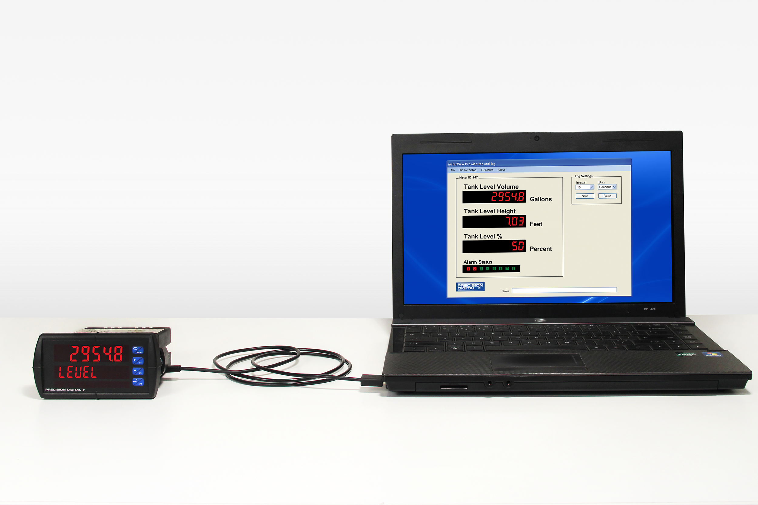
- Free PC-Based, On-Board, MeterView Pro USB Programming Software
- SunBright Display Standard Feature; Great for Outdoor Applications
- Display Rate & Total at the Same Time
- Rate in Units per Second, Minute, Hour, or Day
- Total, Grand Total or Non-Resettable Grand Total
- Front Panel or Remote Total Reset
- Password Protection for Total Reset
- Total Stored in Non-Volatile Memory
- Assign Any Relay or 4-20 mA Output for Rate or Total
- K-Factor, Internal Scaling, or External Calibration
- 4-20 mA Output Option Converts the Pulse Input to an Isolated 4-20 mA Output
- Operating Temperature Range: -55 to 65°C (-67 to 149°F)
- CSA Certified as Explosion-Proof / Dust-Ignition-Proof / Flame-Proof
- ATEX and IECEx Certified as Dust-Ignition-Proof / Flame-Proof
- Input Power Options: 85-265 VAC / 90-265 VDC or 12-24 VDC / 12-24 VAC
- Programmable Display, Function Keys & Digital Inputs
- Flanges for Wall or Pipe Mounting
- Explosion-Proof Aluminum or Stainless Steel NEMA 4X / IP68 Enclosures
- On-Board RS-485 Serial Communications
- Modbus RTU Communication Protocol Standard
- Password Protection
- Four 3/4" NPT Threaded Conduit Openings
- 3-Year Warranty
** NEW IMPROVED WEB STORE! | All users must register for a new account. | Register now > **
BUY ONLINE TO SAVE TIME AND INCREASE ORDER ACCURACY!

Questions? (508) 655-7300
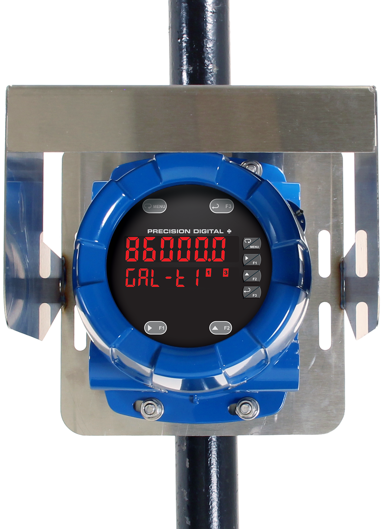
ProtEX-MAX Explosion-Proof Pulse Input Flow Rate/Totalizer
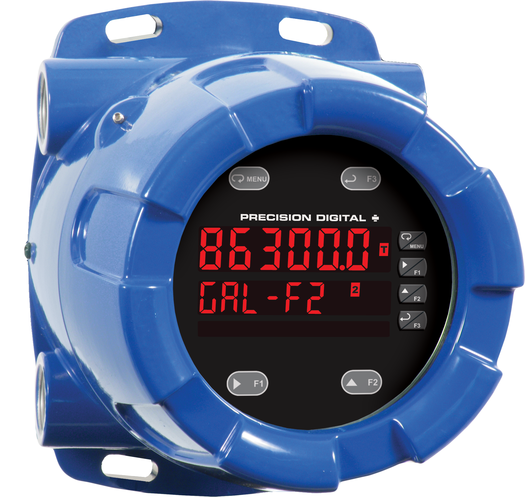
PD8-6300 in Aluminum Enclosure


Models in stock
from $1633.00
The ProtEX-MAX PD8-6300 offers all the functionality of the ProVu PD6300 as a CSA, ATEX, and IECEx certified explosion-proof product. It is available in an aluminum or stainless steel enclosure and will operate over a wide temperature range of -55 to 65°C (-67 to 149°F). It is specifically designed to display flow rate and total from a pulse output (NPN, PNP, TTL, switch contact, sine wave, etc.) flowmeter. It displays that signal on a dual-line, 6-digit Sunbright sunlight readable display. Flow rate is typically displayed on the upper line and the cumulative total is displayed on the lower line. The total overflow feature allows up to a 9-digit total and grand total to be displayed. The PD8-6300 includes a 24 VDC power supply to drive the flowmeter and can be equipped with four internal relays and a 4-20 mA analog output. It can be programmed and operated without opening the housing by using the built-in CapTouch through-glass buttons or the RS-485 serial communication port with free Modbus protocol.
Why Should You Buy:
- Worldwide Explosion-Proof Approvals
- Displays Flow Rate and Total
- Pulse Input
- USB Programming