- 0-20 mA, 4-20 mA, 0-5 V, 1-5 V, and ±10 V Inputs
- Rate, Total, and Grand Total for Each Input Channel
- Addition, Difference, Average, Multiplication, Division, Min, Max, Weighted Average, Ratio, Concentration, & More
- NEMA 4X, IP65 Front
- Available with Universal 85-265 VAC or 12/24 VDC Input Power
- Large Dual-Line 6-Digit Display, 0.60" & 0.46"
- 2 or 4 Relays + Isolated 4-20 mA Output Options
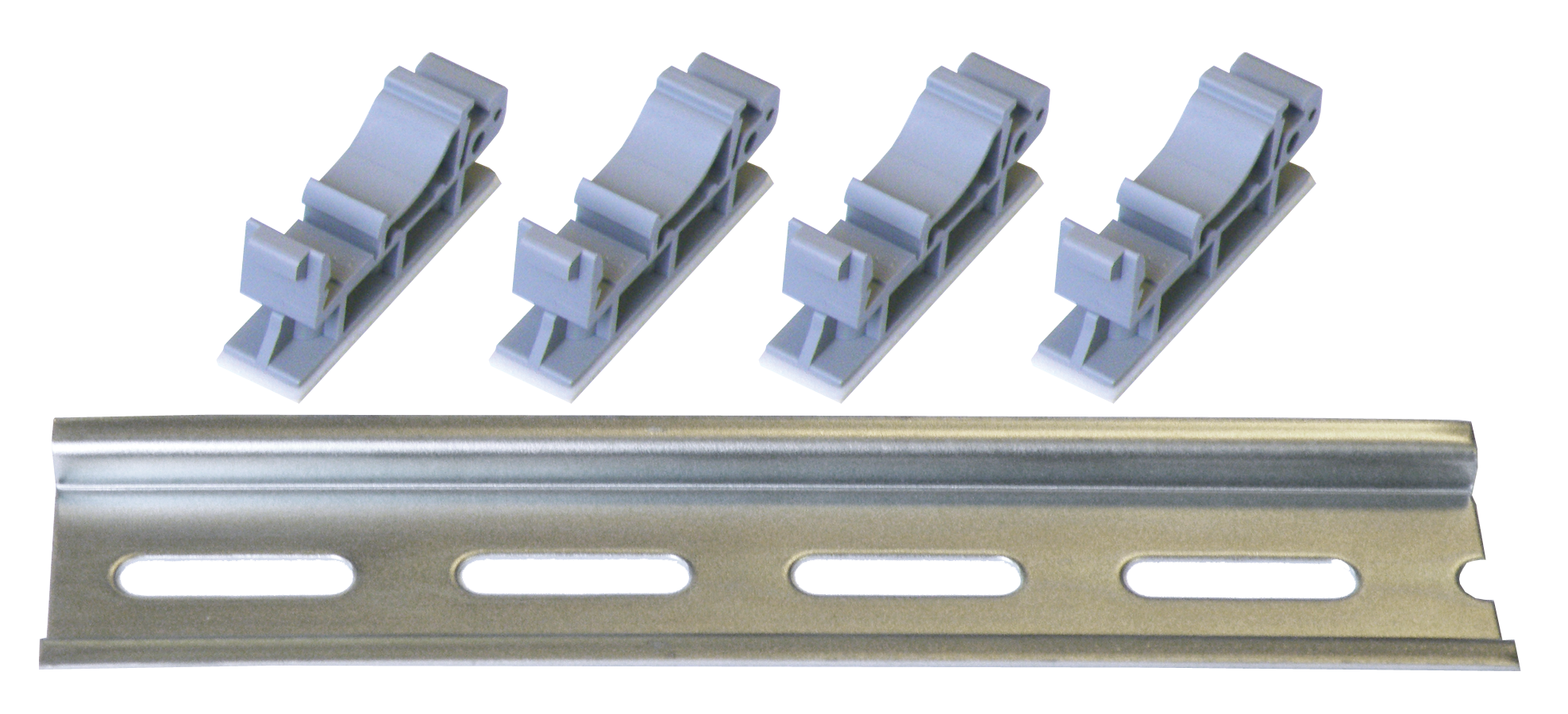
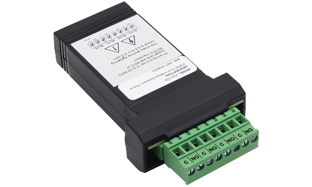
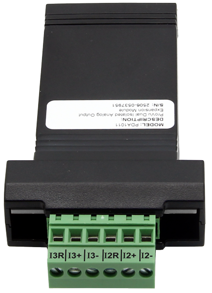
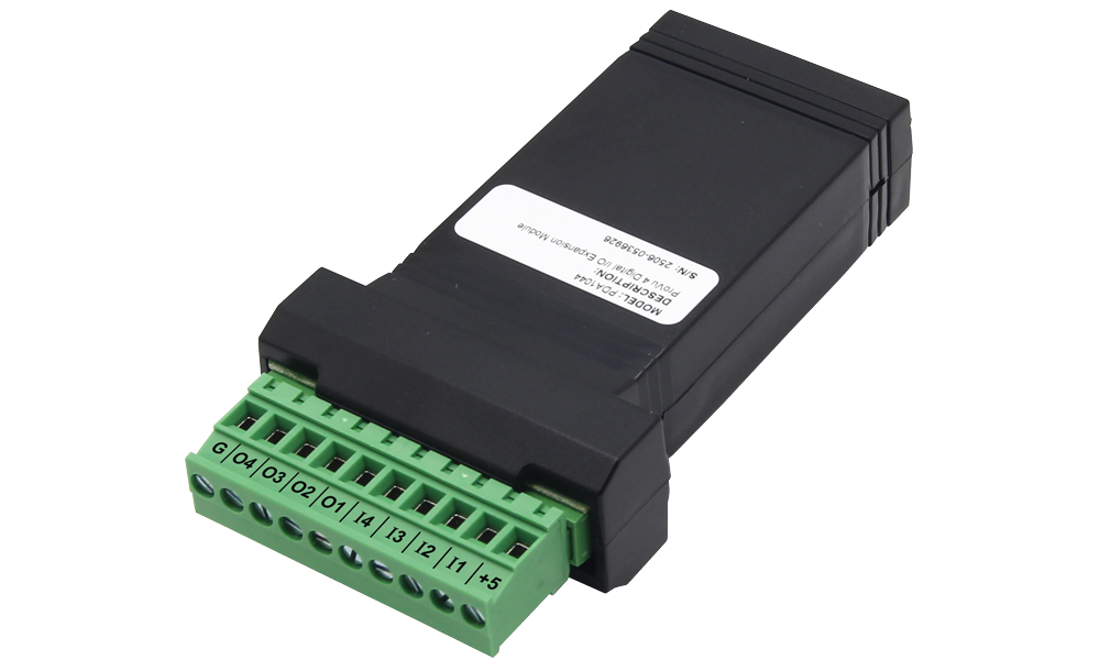
- External 4-Relay, Dual Analog Output, and Digital I/O Expansion Modules
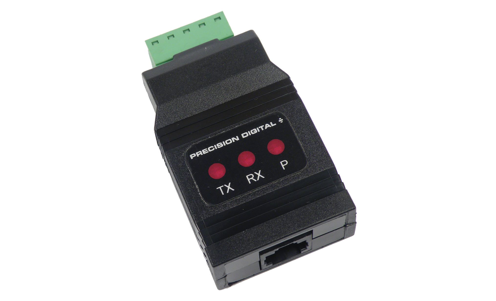
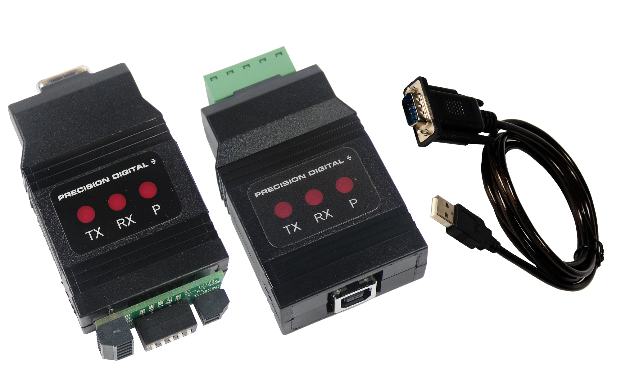
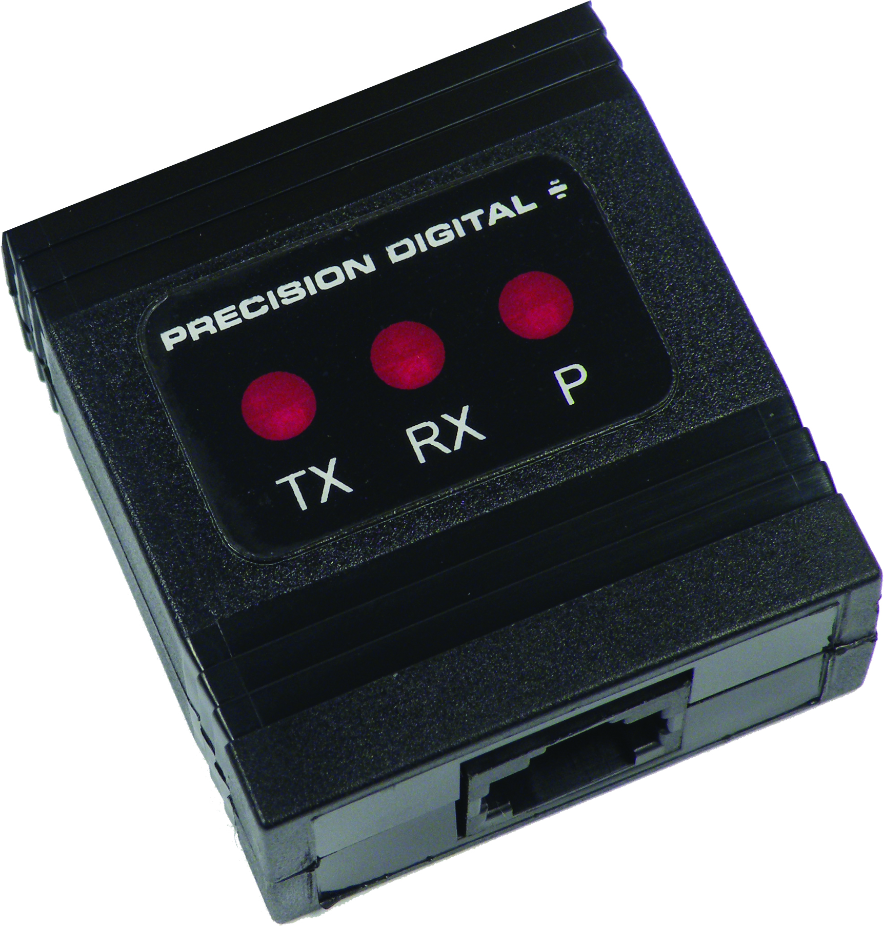
- USB, RS-232, & RS-485 Serial Communications Expansion Modules
- On-Board Digital Input
- Modbus RTU Communication Protocol Standard
- Isolated 24 VDC Transmitter Power Supply
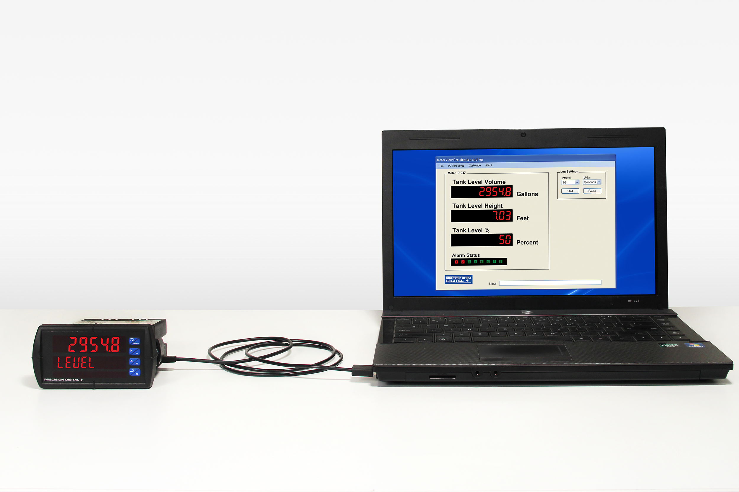
- Configure, Monitor, and Datalog from a PC with Free MeterView Pro Software
- Optional SunBright Display Models for Outdoor Applications
- Onboard USB and MeterView Pro Programming Software
** NEW IMPROVED WEB STORE! | All users must register for a new account. | Register now > **
BUY ONLINE TO SAVE TIME AND INCREASE ORDER ACCURACY!

Questions? (508) 655-7300
- Accessories
- Annunciators & Scanners
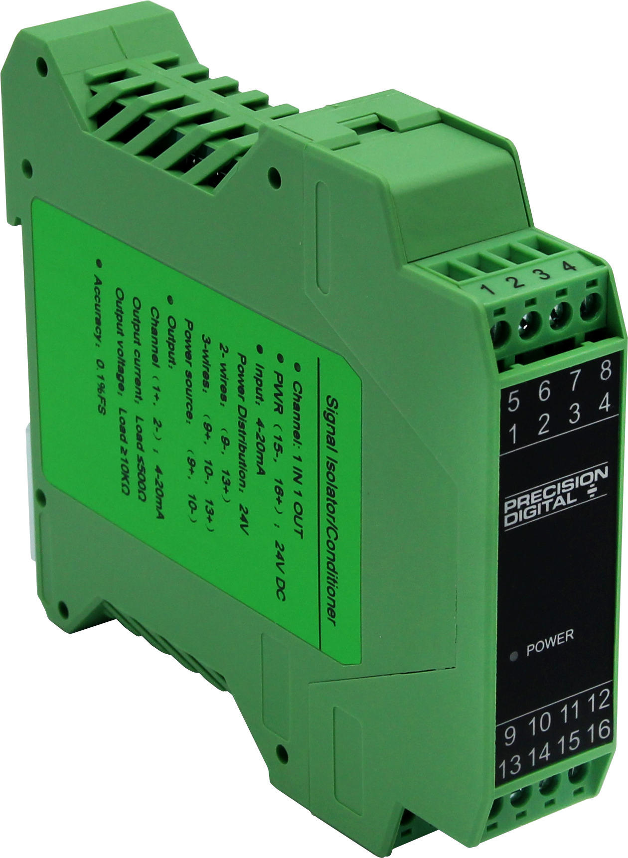
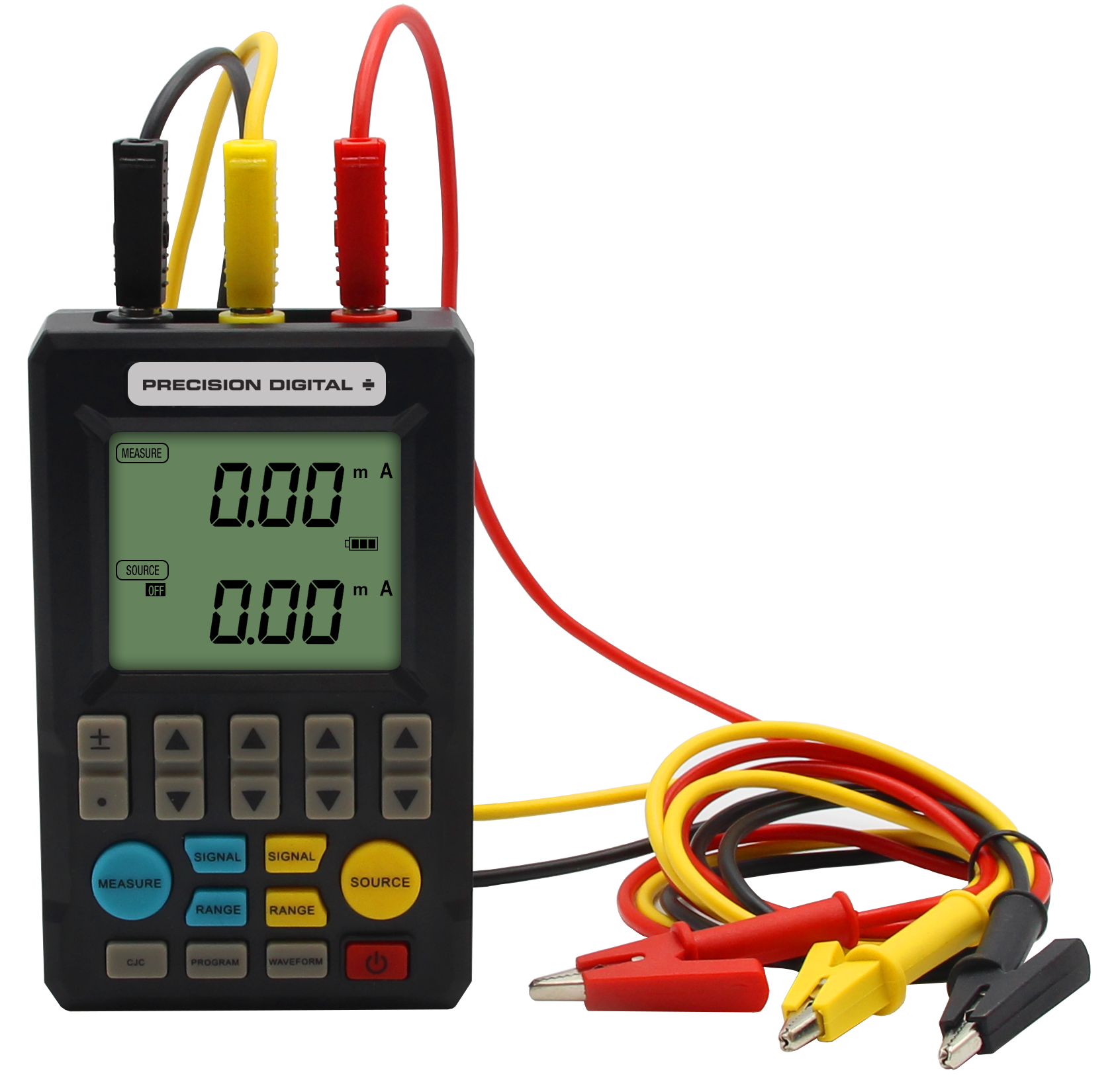
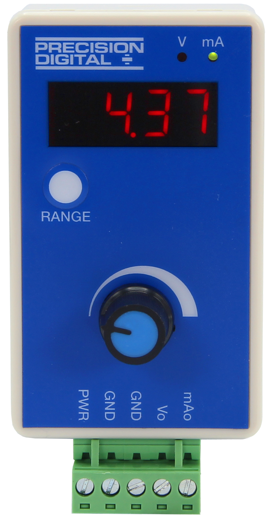
- Calibrators, Signal Isolators, Splitters, & Generators
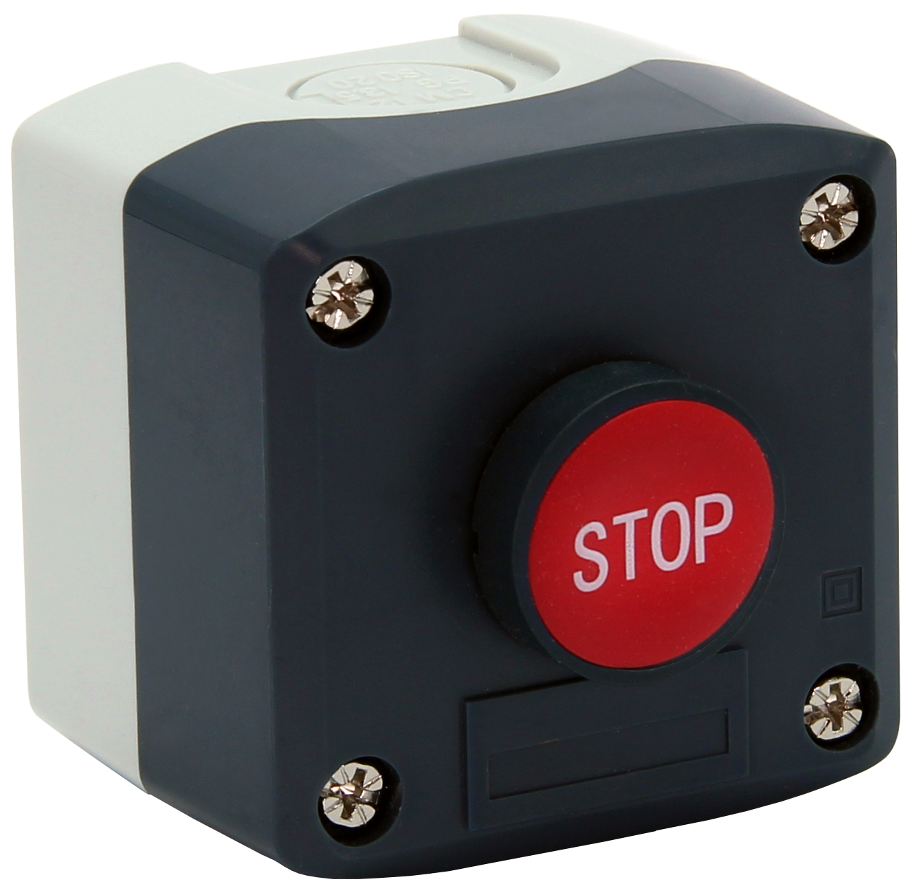
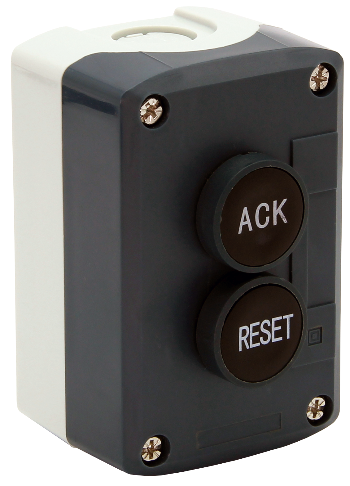
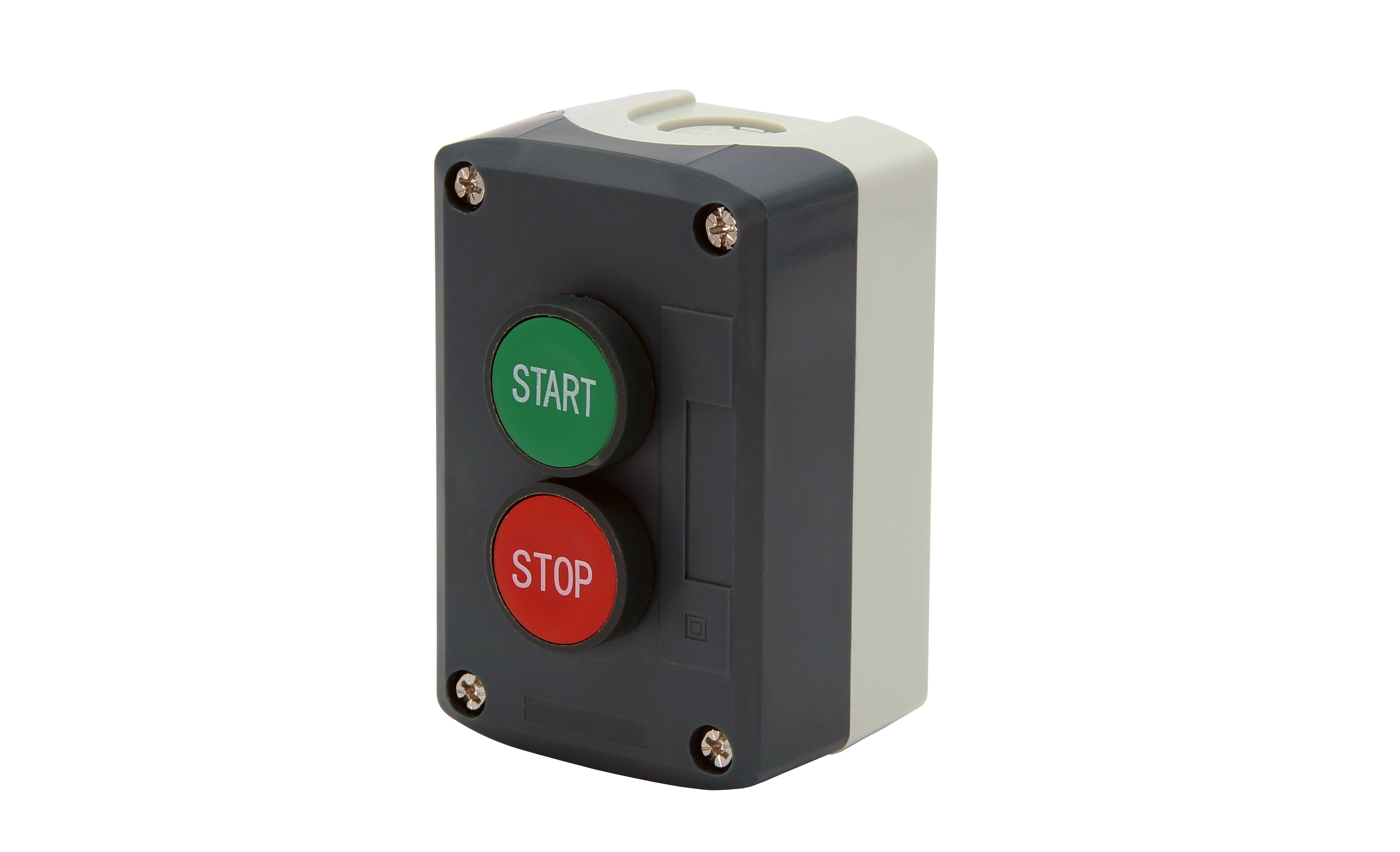
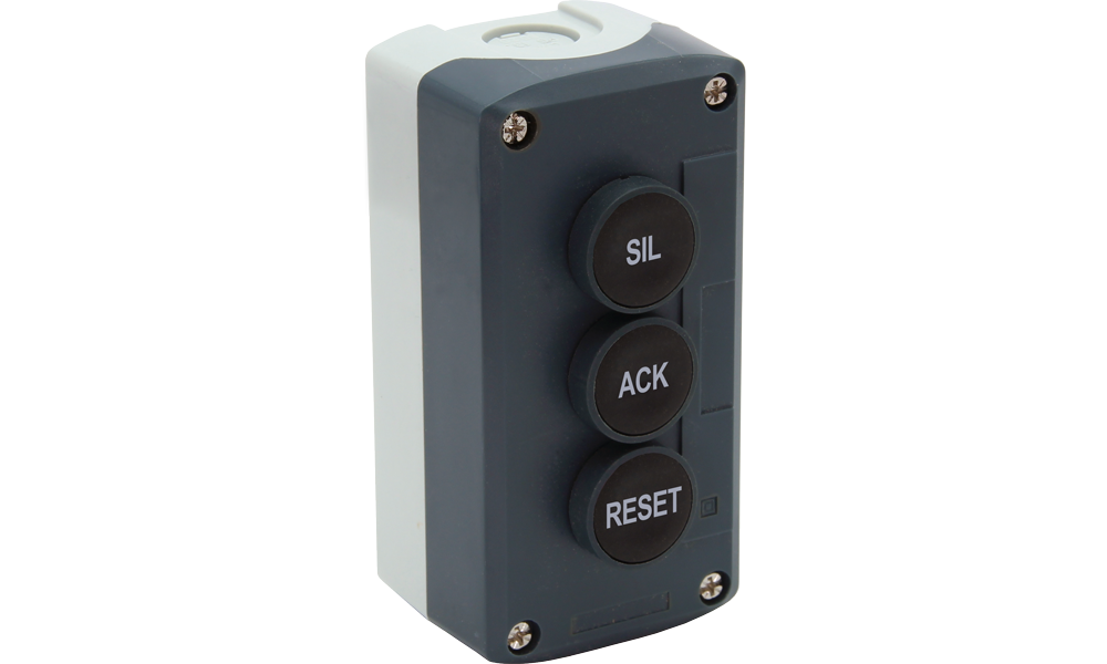
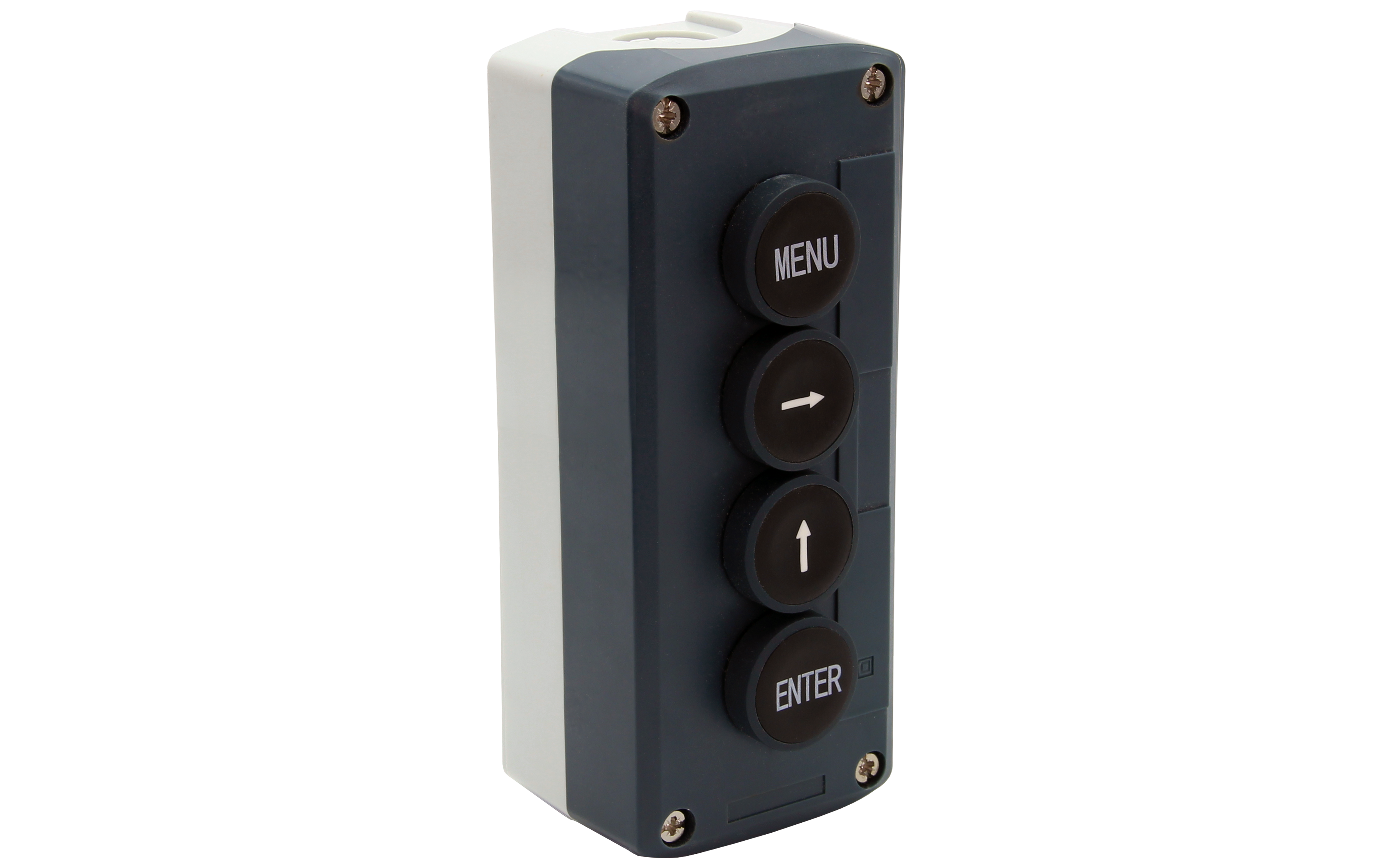
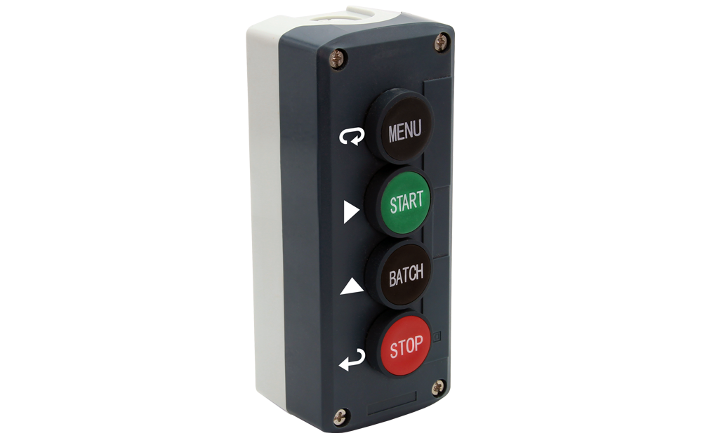
- Control Stations
- Custom Enclosure Assembly
- Demo Units
- Digital Panel Meters
- Enclosures
- Explosion-Proof
- Field-Mount Indicators
- Industrial Wireless
- Intrinsically Safe
- Large Display
- Light/Horn
- Loop-Powered Meters
- Modbus Displays
- Modifications
- Multi-Channel Controllers
- Process Value Alarm Enclosure Assembly
- Sun Hoods
- Subpanel Wiring Assembly
- Temperature Controllers
- Level
- Level (Feet & Inches)
- Process
- Pressure
- Temperature
- Flow Rate/Totalizer
- Pump Control
- Chemical Bulk Storage
- Strain Gauge
- Load Cell
- Hazardous Area
- Industrial Wireless
- Batch Control
- PID Control
- Modbus
- Annunciator
- Calibration
- Data Logging
- Signal Conditioning
- Signal Generation
- Signal Isolating
- Signal Splitting
- High Current
- Speed
- Weight

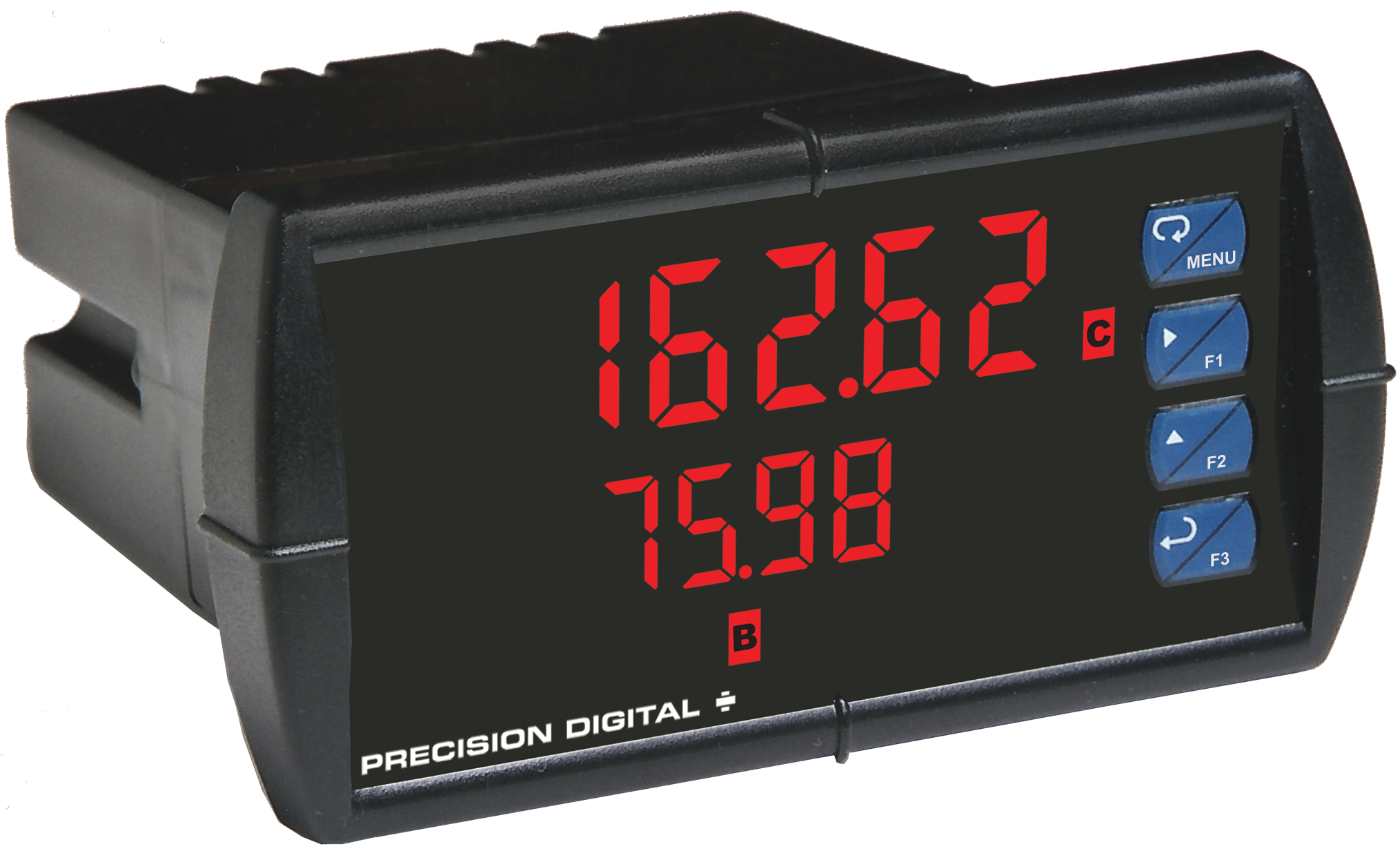
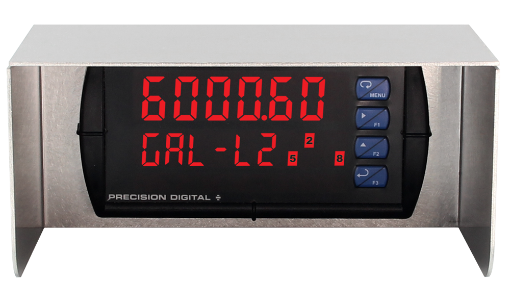
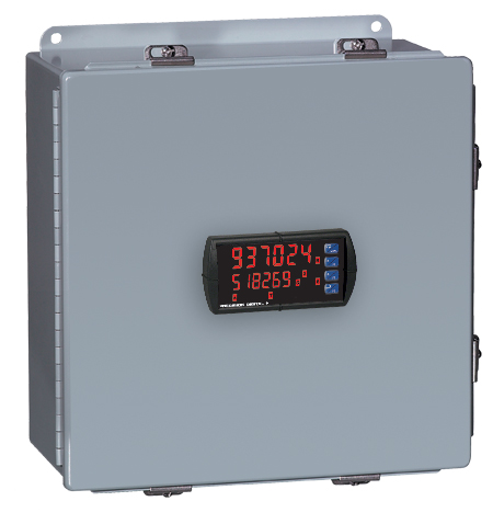
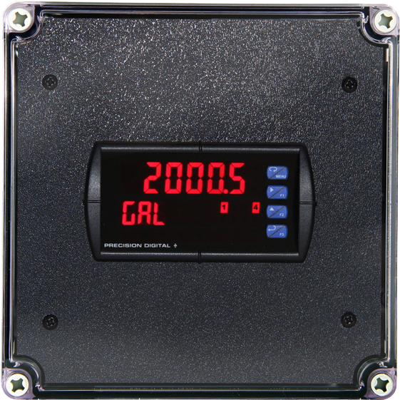
ProVu Dual Analog Input Flow Rate/Totalizer
PD6262 Left


Models in stock
from $704.00
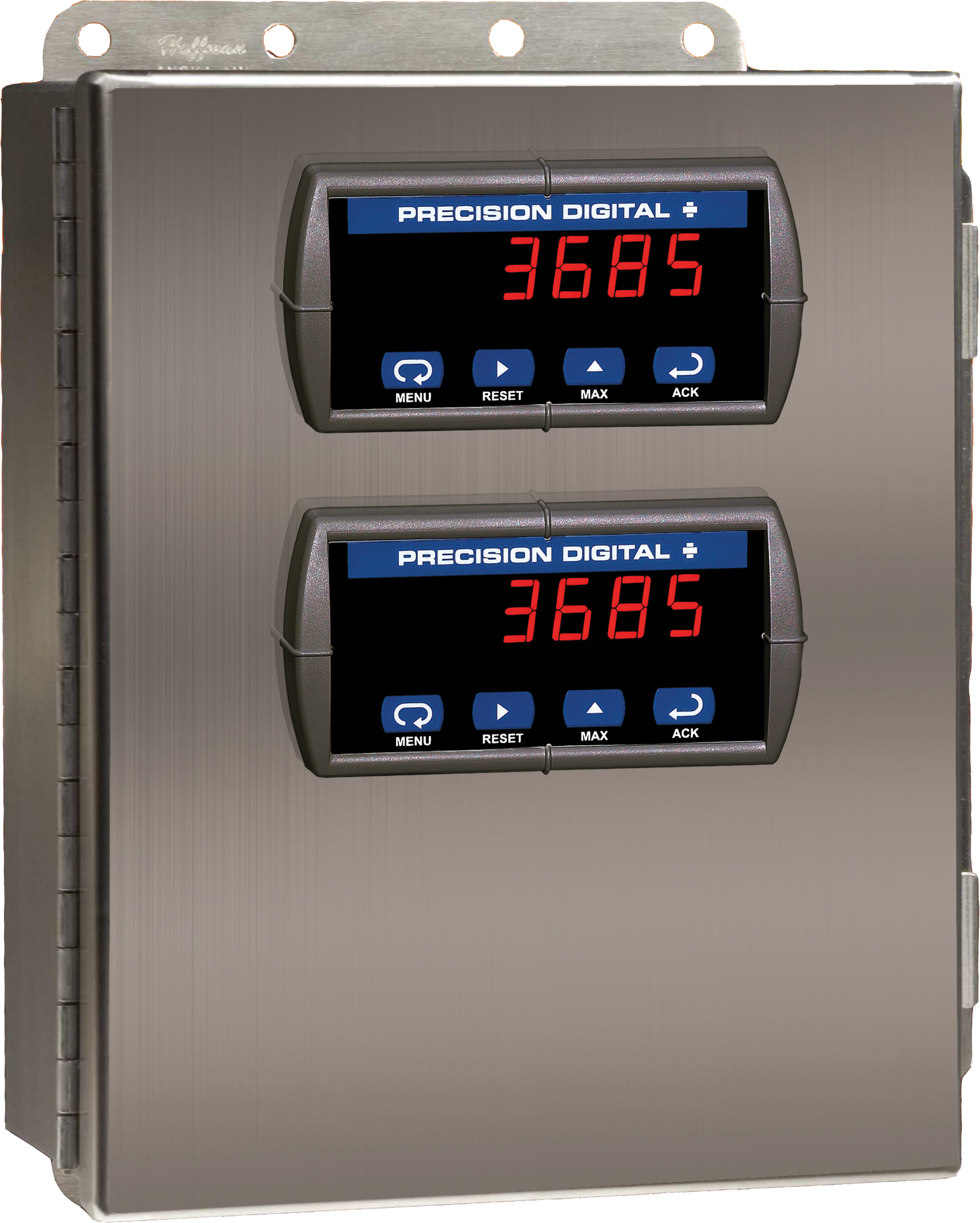
The PD6262 is a member of the ProVu series of 1/8 DIN digital panel meters that is specifically designed to display flow rate and total from two (2) analog output (4-20 mA, 0-5 V, 1-5 V, etc.) flowmeters. It displays these signals on a dual-line, 6-digit display that is available with optional Sunbright sunlight readable LEDs. The dual-line display can be used to show both flow rates simultaneously, to alternate between the two inputs showing both the flow rate and total of each, or to show the result of math functions performed on the flow rates and totals. Like all ProVu meters, the PD6262 includes UL / C-UL listing and CE marking, a NEMA 4X front, and AC or DC power options. ProVu meters can be equipped with up to four internal relays, a 4-20 mA output, and Modbus RTU serial communications. The PD6262 dual-input flow rate/totalizer includes a 24 VDC power supply to drive the flowmeter and can be programmed via the front panel pushbuttons or free MeterView Pro software.
- Dual Analog Rate Inputs
- Math Functions
- USB Programming

The PD6262 is a member of the ProVu series of 1/8 DIN digital panel meters that is specifically designed to display flow rate and total from two (2) analog output (4-20 mA, 0-5 V, 1-5 V, etc.) flowmeters. It displays these signals on a dual-line, 6-digit display that is available with optional Sunbright sunlight readable LEDs. The dual-line display can be used to show both flow rates simultaneously, to alternate between the two inputs showing both the flow rate and total of each, or to show the result of math functions performed on the flow rates and totals. Like all ProVu meters, the PD6262 includes UL / C-UL listing and CE marking, a NEMA 4X front, and AC or DC power options. ProVu meters can be equipped with up to four internal relays, a 4-20 mA output, and Modbus RTU serial communications. The PD6262 dual-input flow rate/totalizer includes a 24 VDC power supply to drive the flowmeter and can be programmed via the front panel pushbuttons or free MeterView Pro software.
Inches (mm)


×![Enlarged View]()
Documentation & Resources
Product Information (3)
Modbus Register Tables (1)
Configure, monitor, or datalog ProVu, Helios, or ProtEX-MAX meters using the PC-based MeterView Pro (MVP) software. MVP is available here as a free download and makes complete meter configuration simple and fast. Copying one meter configuration to another, as well as saving or retrieving a meter configuration file, is a snap. MVP's linearization utility makes even a 32-point linearization task clear and easy to do.
Also included is a basic meter monitor and data logger for use with the meter. Of course, with the inclusion of the powerful Modbus protocol, custom programs can be made even more versatile.
IMPORTANT!
Uninstall previous versions before downloading and running the latest version.
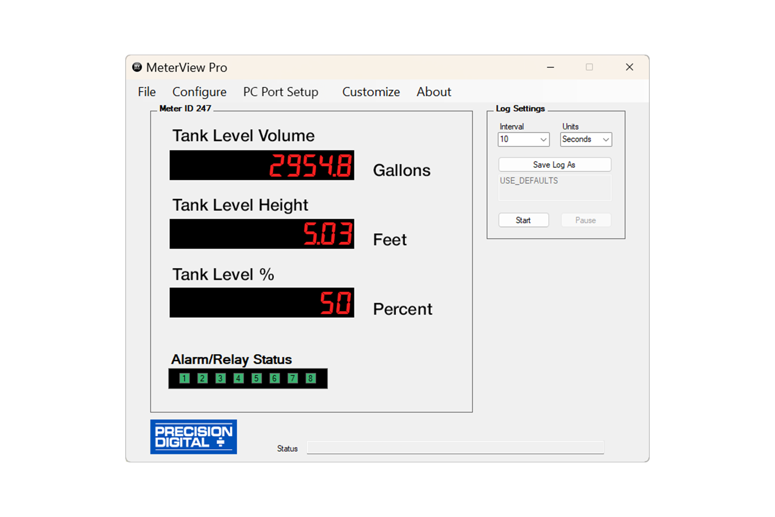
MeterView Pro software can be installed on any Microsoft Windows 10/11 computer. Connect one end of a USB cable to the meter and the other end to the computer. The meter is powered via USB, so there is no need to wire anything before programming it. USB connection is intended for configuration purposes only.
General
System Requirements
Microsoft Windows 10/11
Availability
Communications
Onboard USB (firmware version 4.0 or higher), RS-232 Adapter, or RS-485 Adapter
Reports
Data logging: Save as CSV file format.
Configuration: Save as PDC file format or print configuration
Baud Rate
300 - 19,200 bps
Configuration
One meter at a time
Protocol
Modbus RTU (requires ProVu firmware version 2.0 or higher)
Latest Version
4.1.8
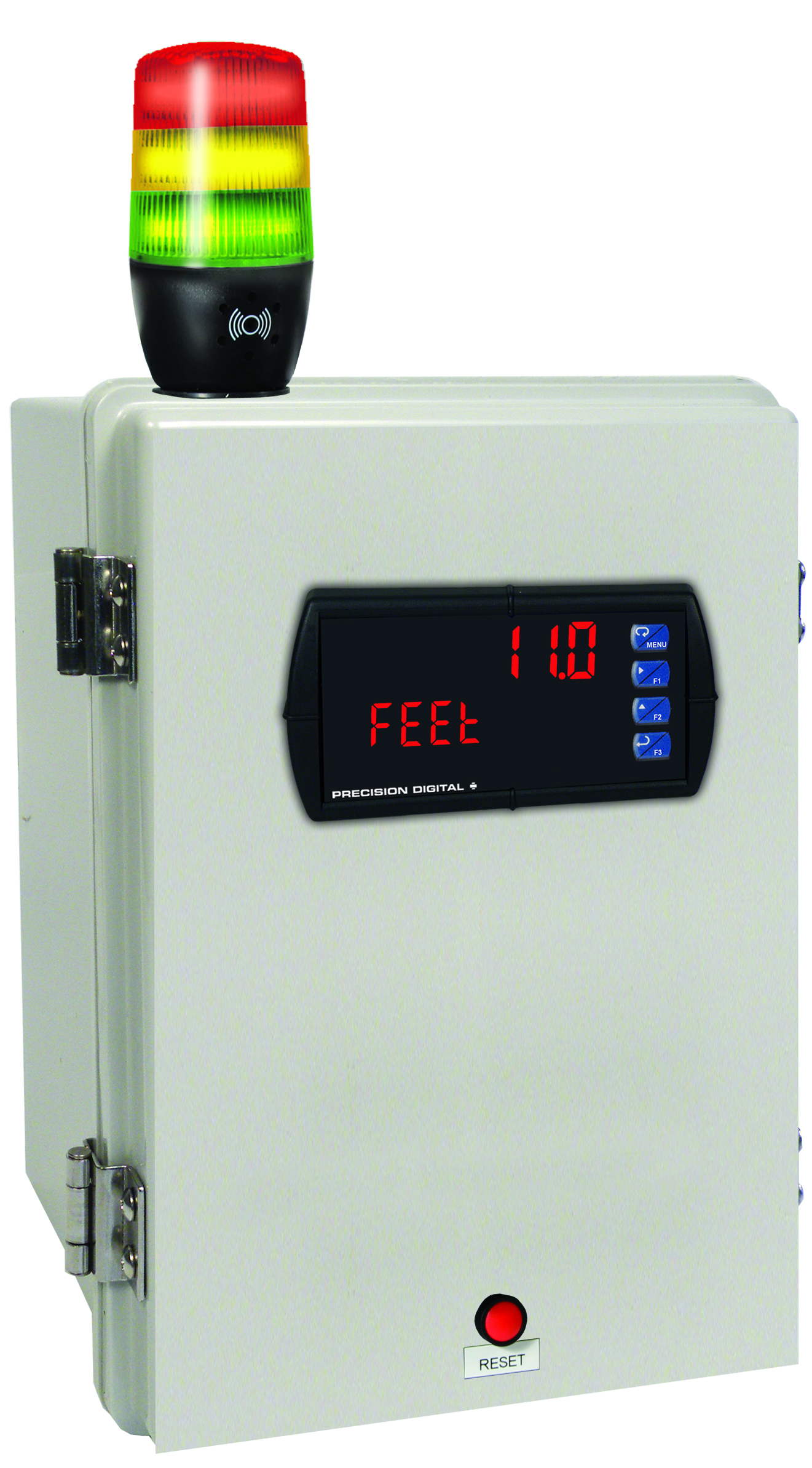
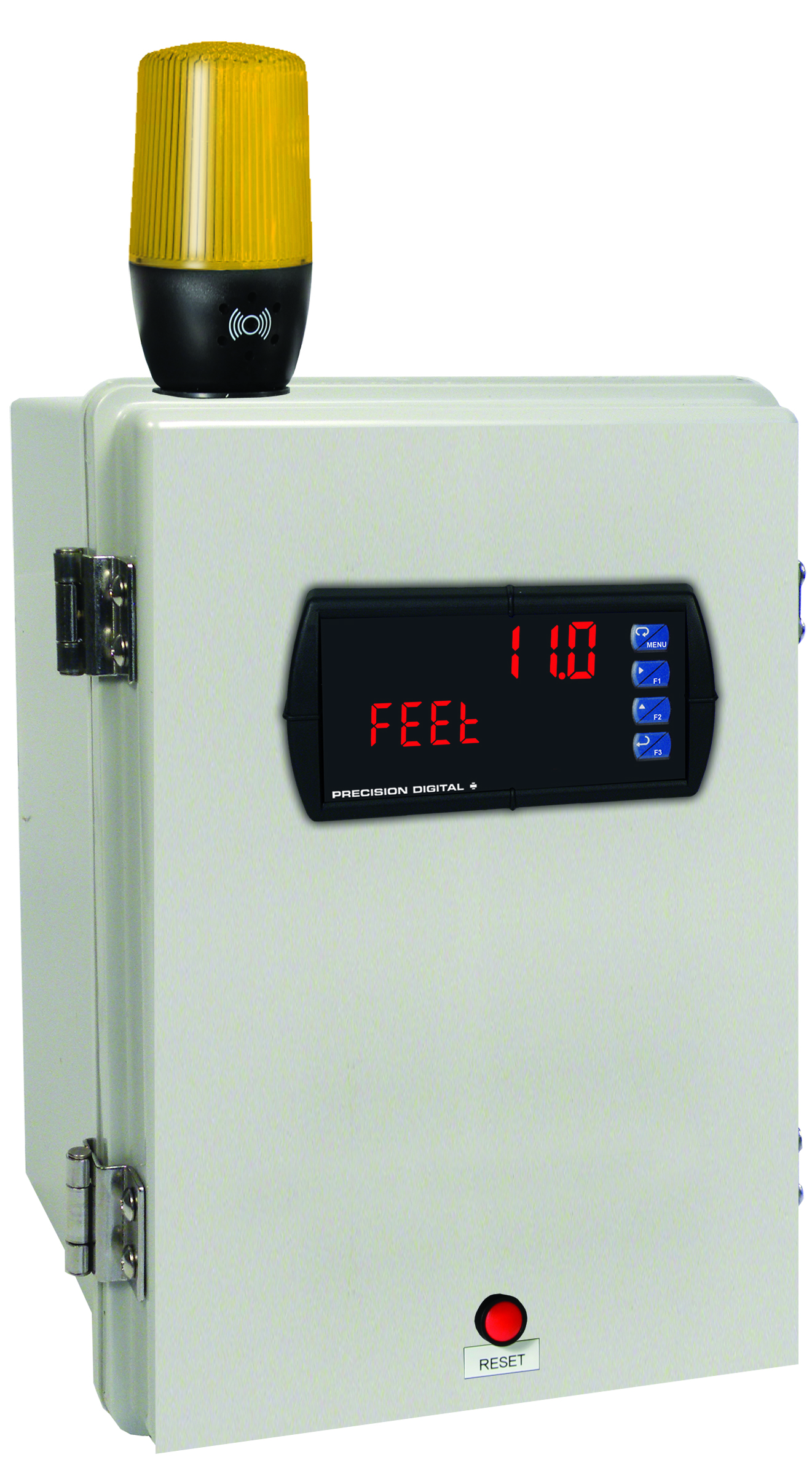
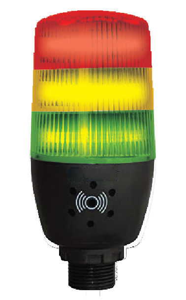
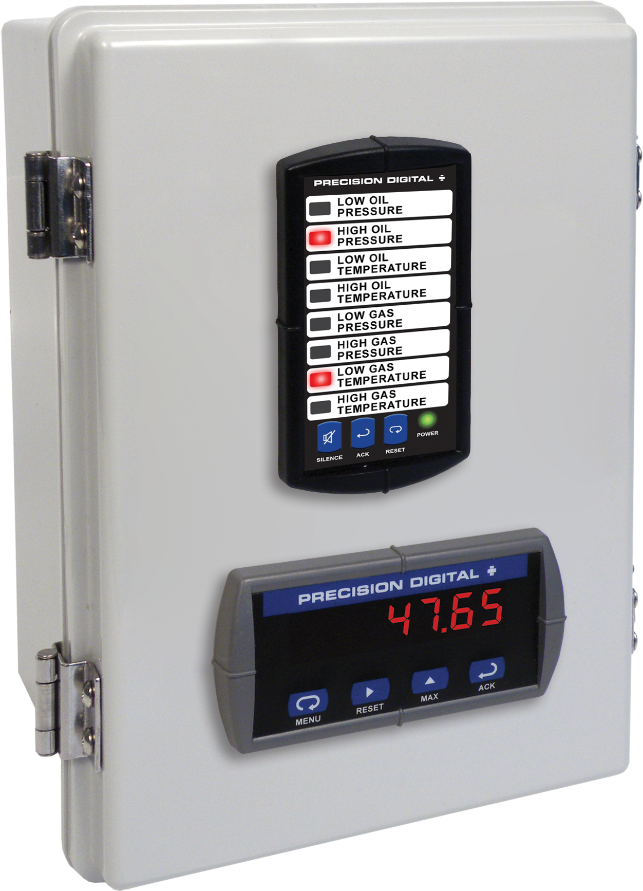
MOD-LH3LCB1-RYG
Modification: Three Color Light/Horn and Reset Button with Holes Drilled for Light/Horn and Reset Button in Enclosure. Enclosure & meter sold separately and assembly required by user.

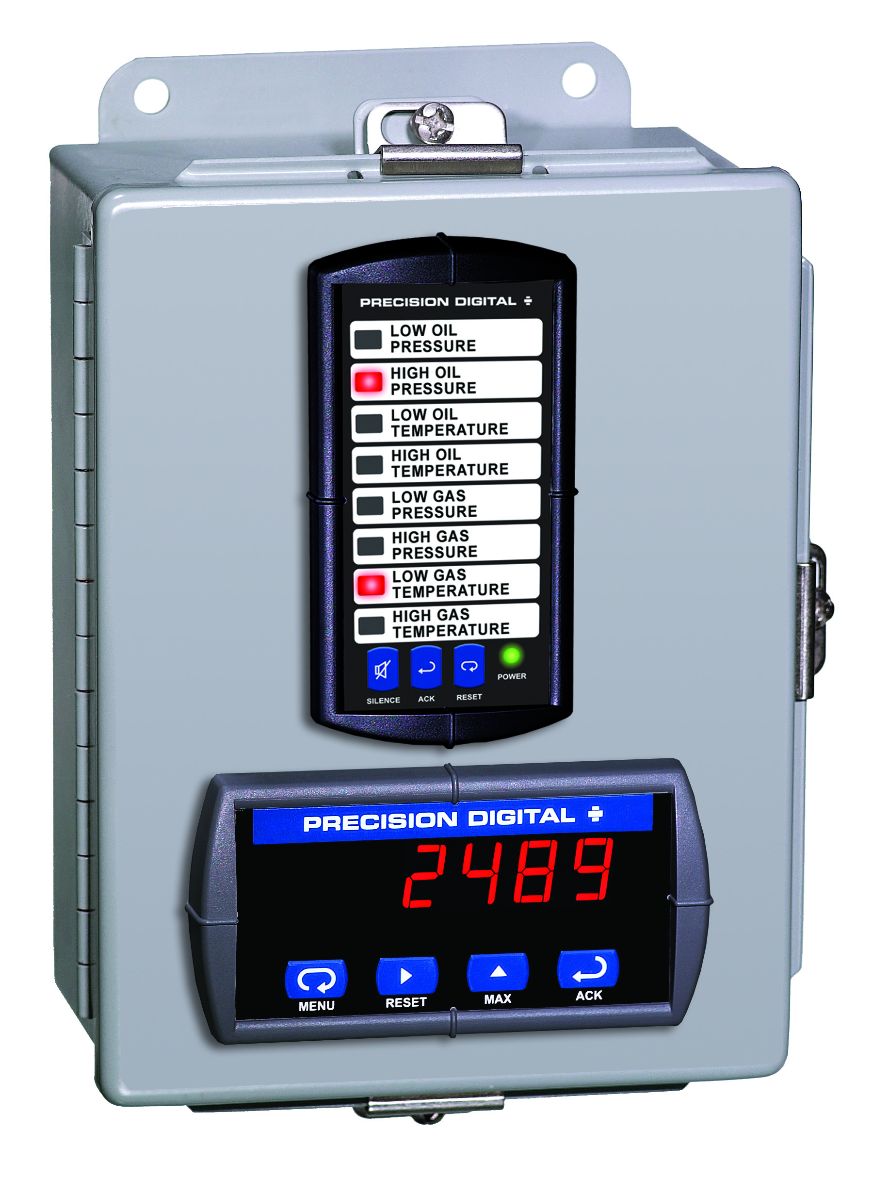
MOD-LH5CB1
Modification: Five Color Light/Horn and Reset Button with Holes Drilled for Light/Horn and Reset Button in Enclosure. Enclosure & meter sold separately and assembly required by user.
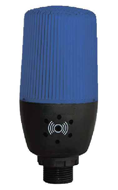
MOD-LHBB1
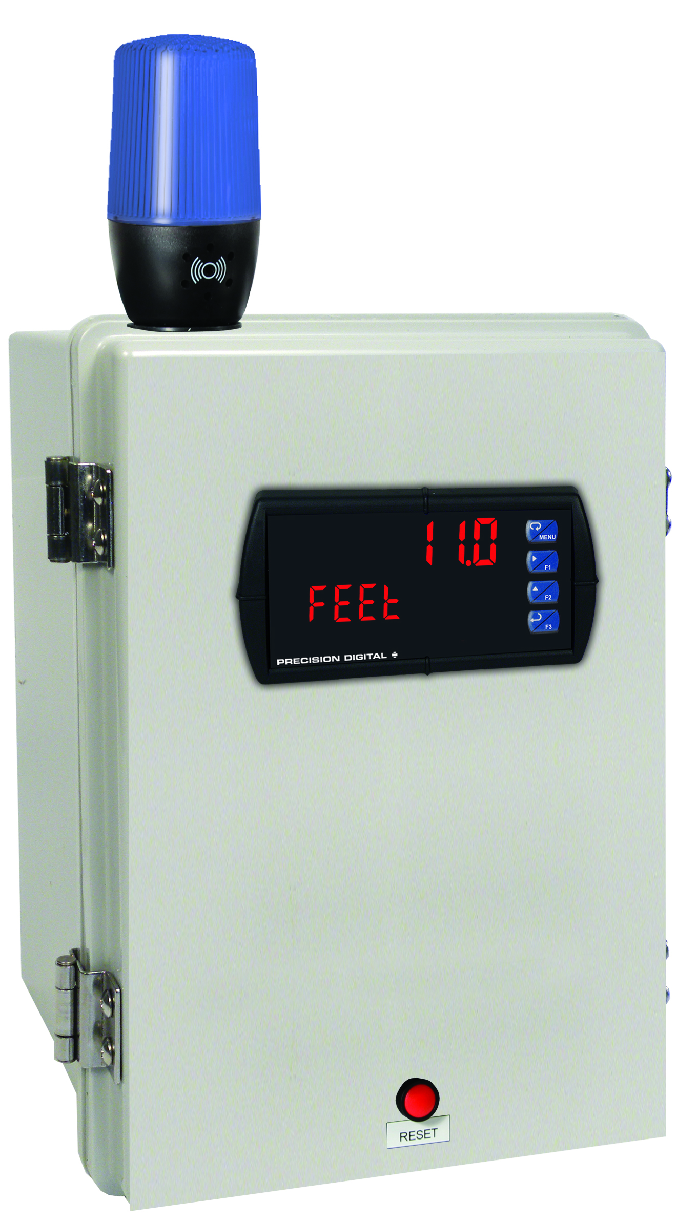
Modification: Blue Light/Horn and Reset Button with Holes Drilled for Light/Horn and Reset Button in Enclosure. Enclosure & meter sold separately and assembly required by user.
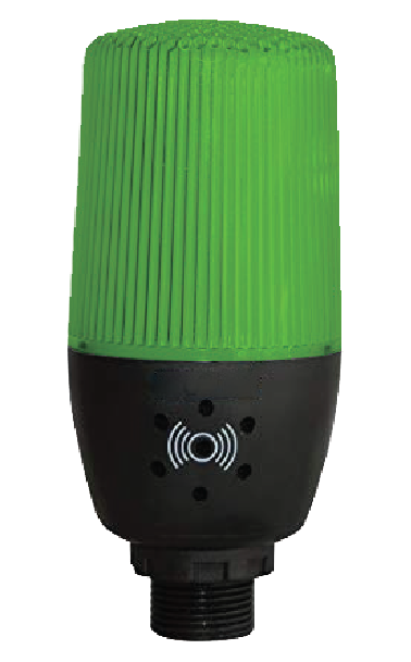
MOD-LHGB1
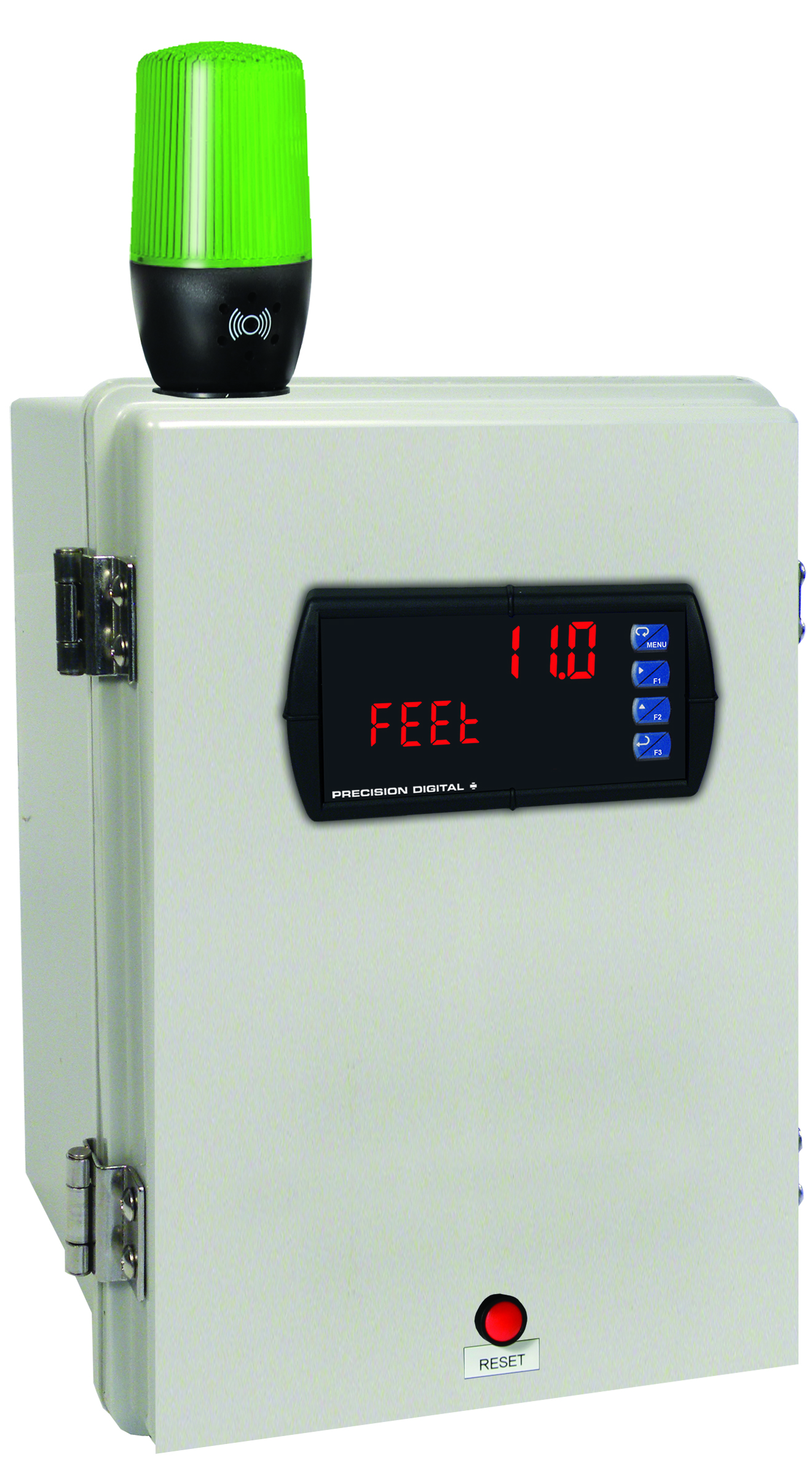
Modification: Green Light/Horn and Reset Button with Holes Drilled for Light/Horn and Reset Button in Enclosure. Enclosure & meter sold separately and assembly required by user.
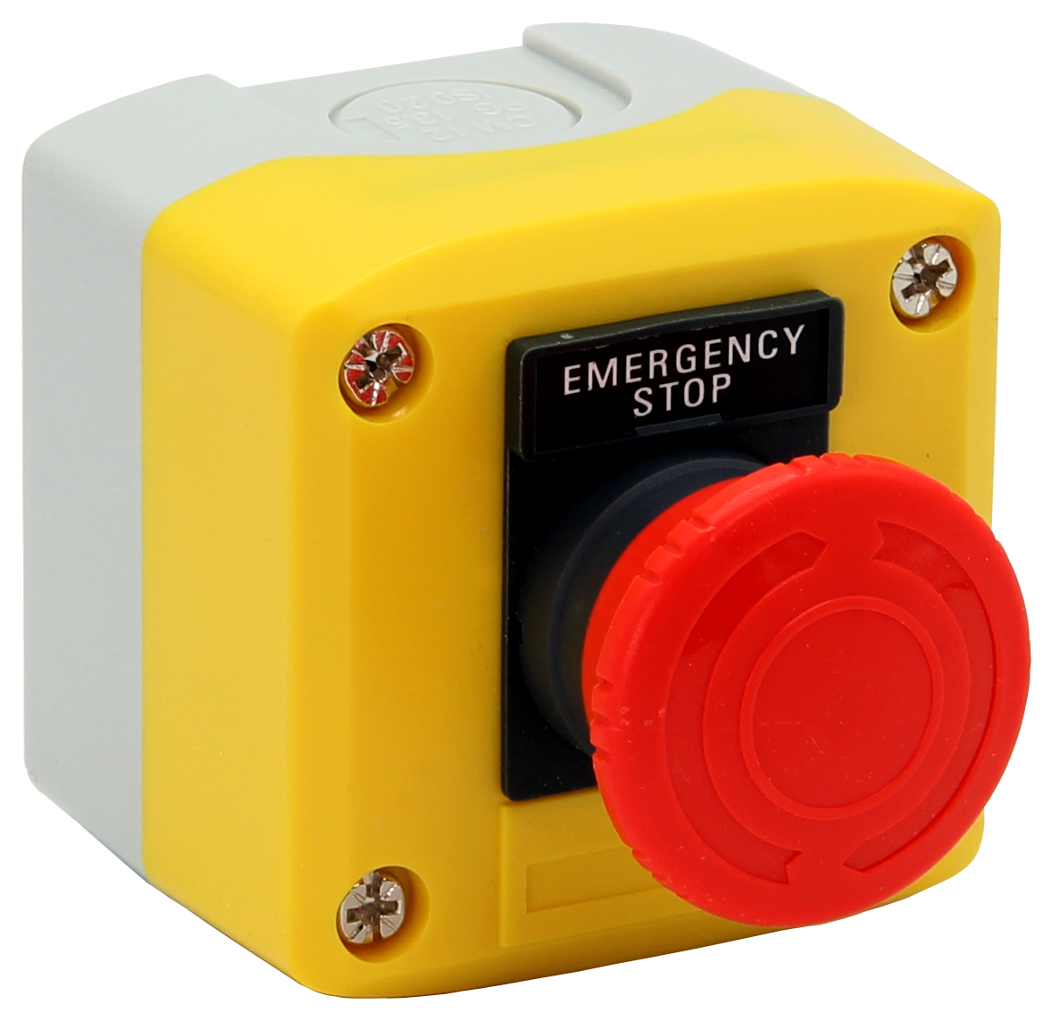
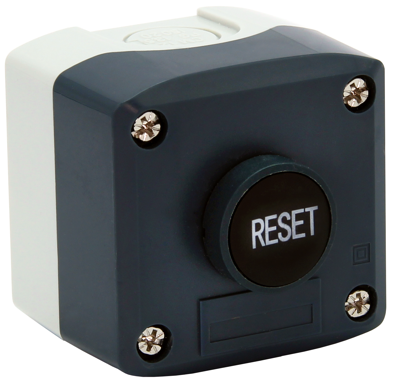
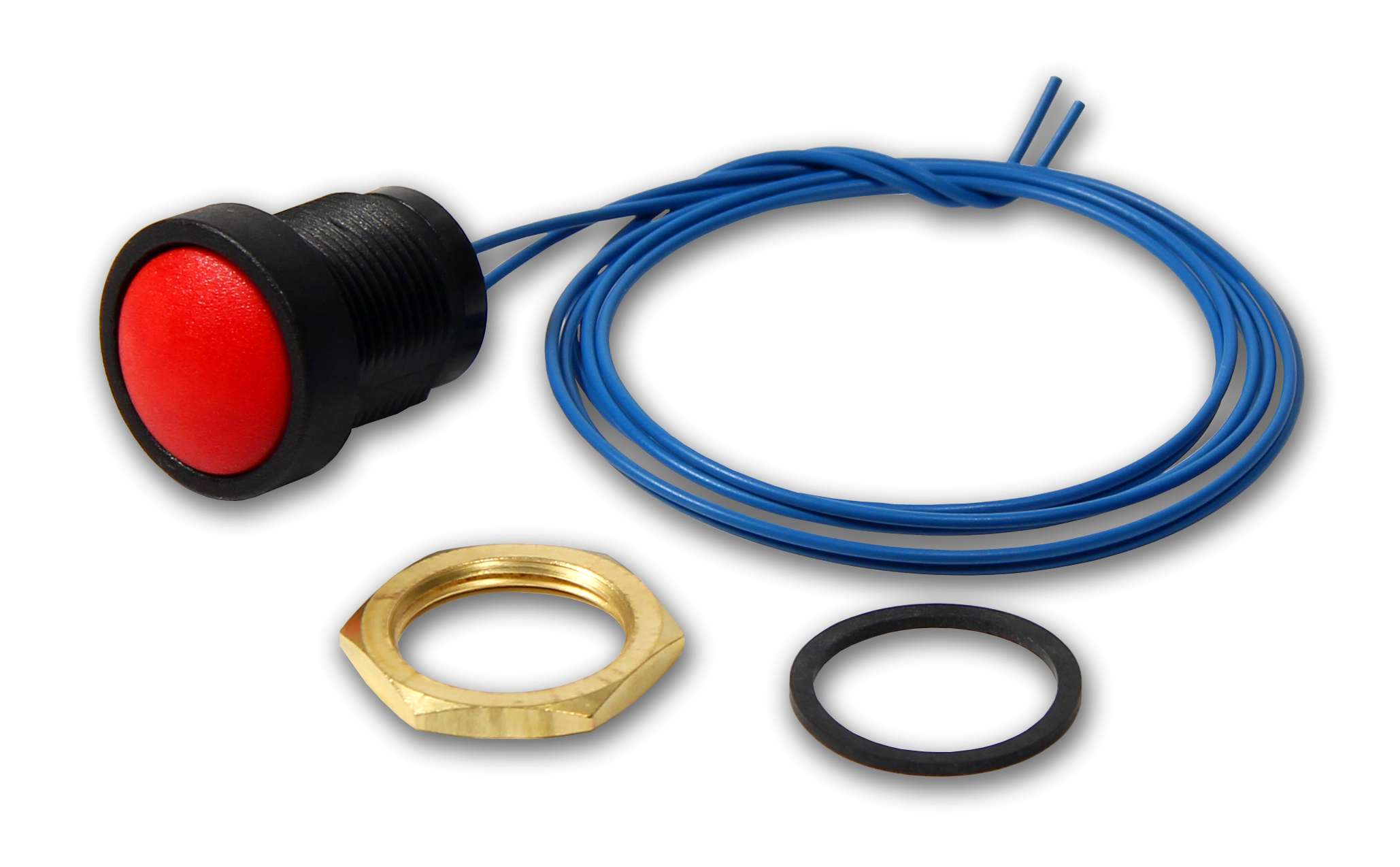
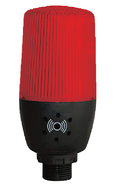
MOD-LHRB1
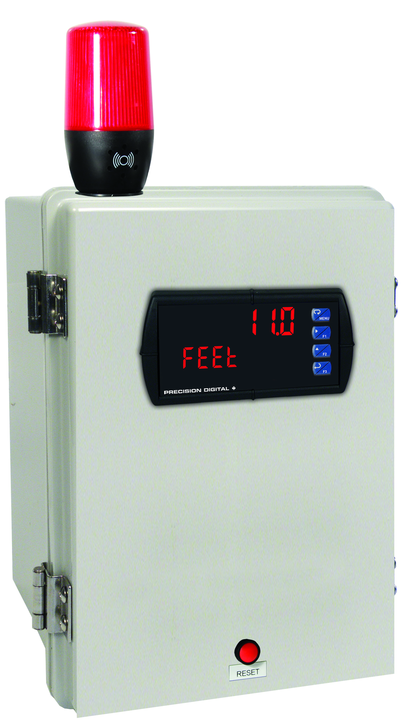
Modification: Red Light/Horn and Reset Button with Holes Drilled for Light/Horn and Reset Button in Enclosure. Enclosure & meter sold separately and assembly required by user.
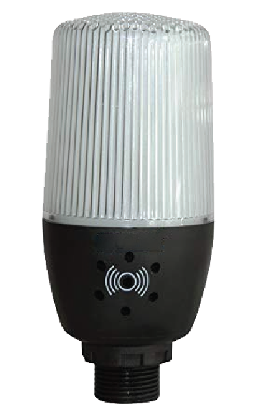
MOD-LHWB1
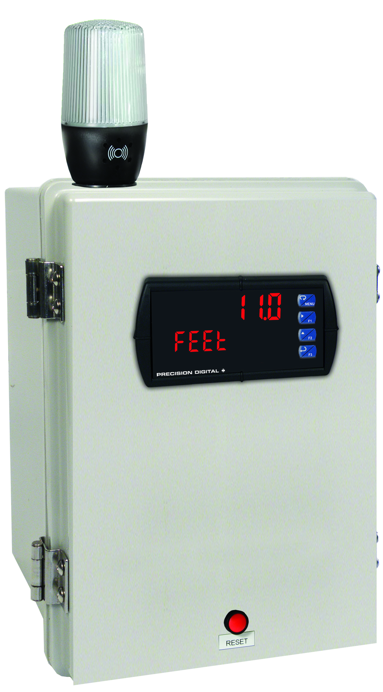
Modification: White Light/Horn and Reset Button with Holes Drilled for Light/Horn and Reset Button in Enclosure. Enclosure & meter sold separately and assembly required by user.
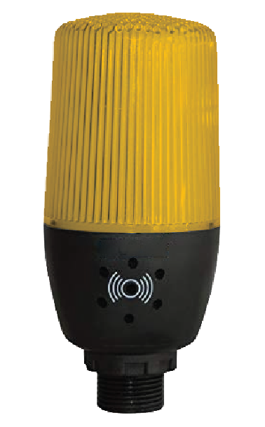
MOD-LHYB1
Modification: Yellow Light/Horn and Reset Button with Holes Drilled for Light/Horn and Reset Button in Enclosure. Enclosure & meter sold separately and assembly required by user.

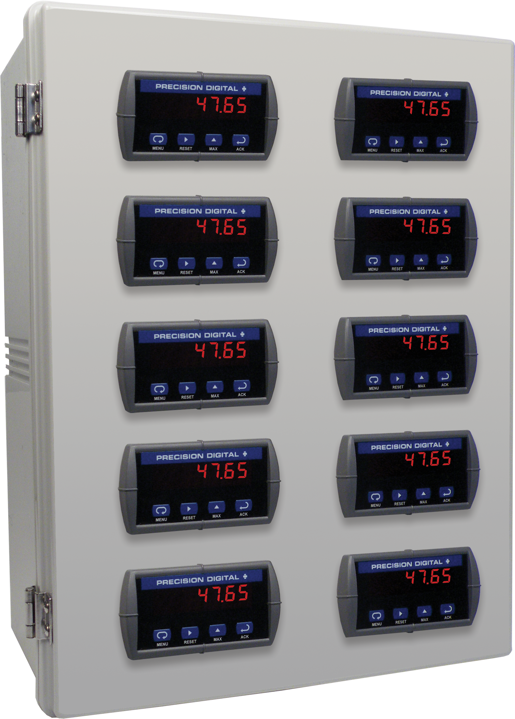
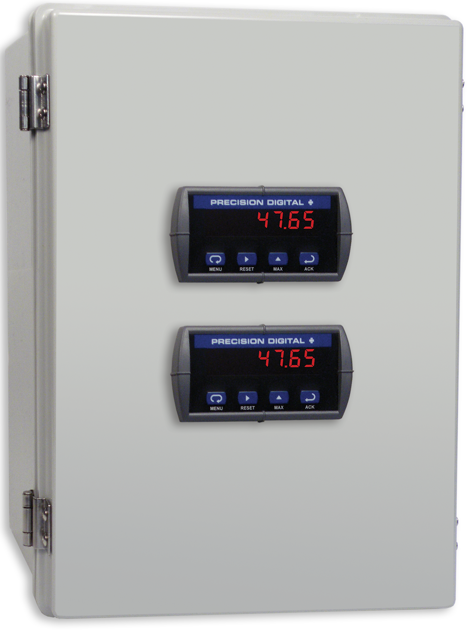
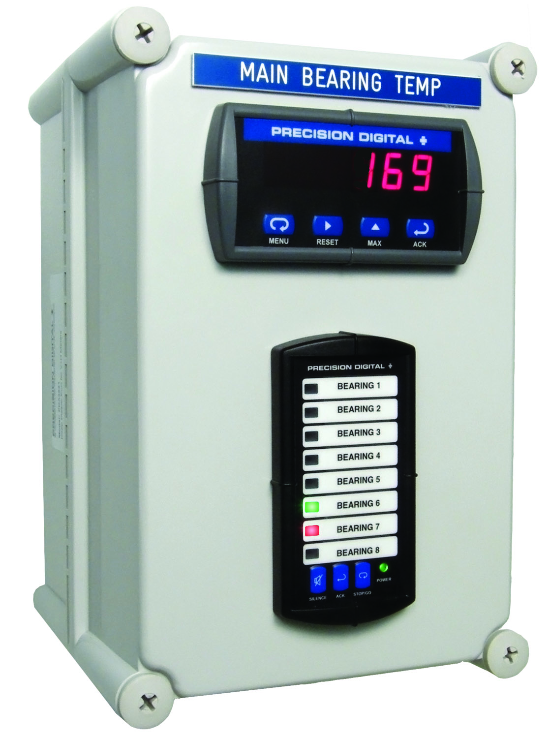
PDA2322
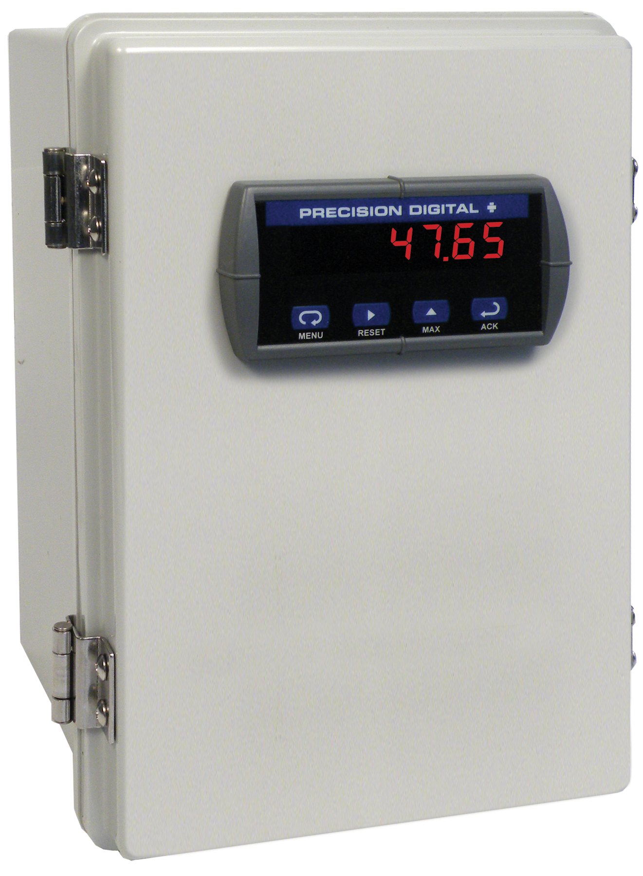
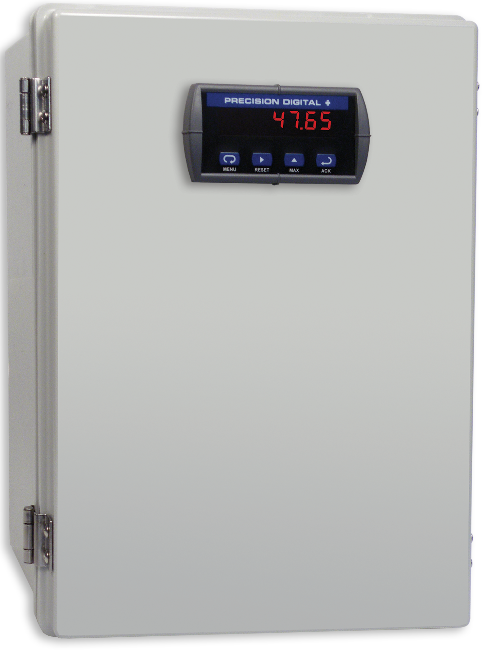
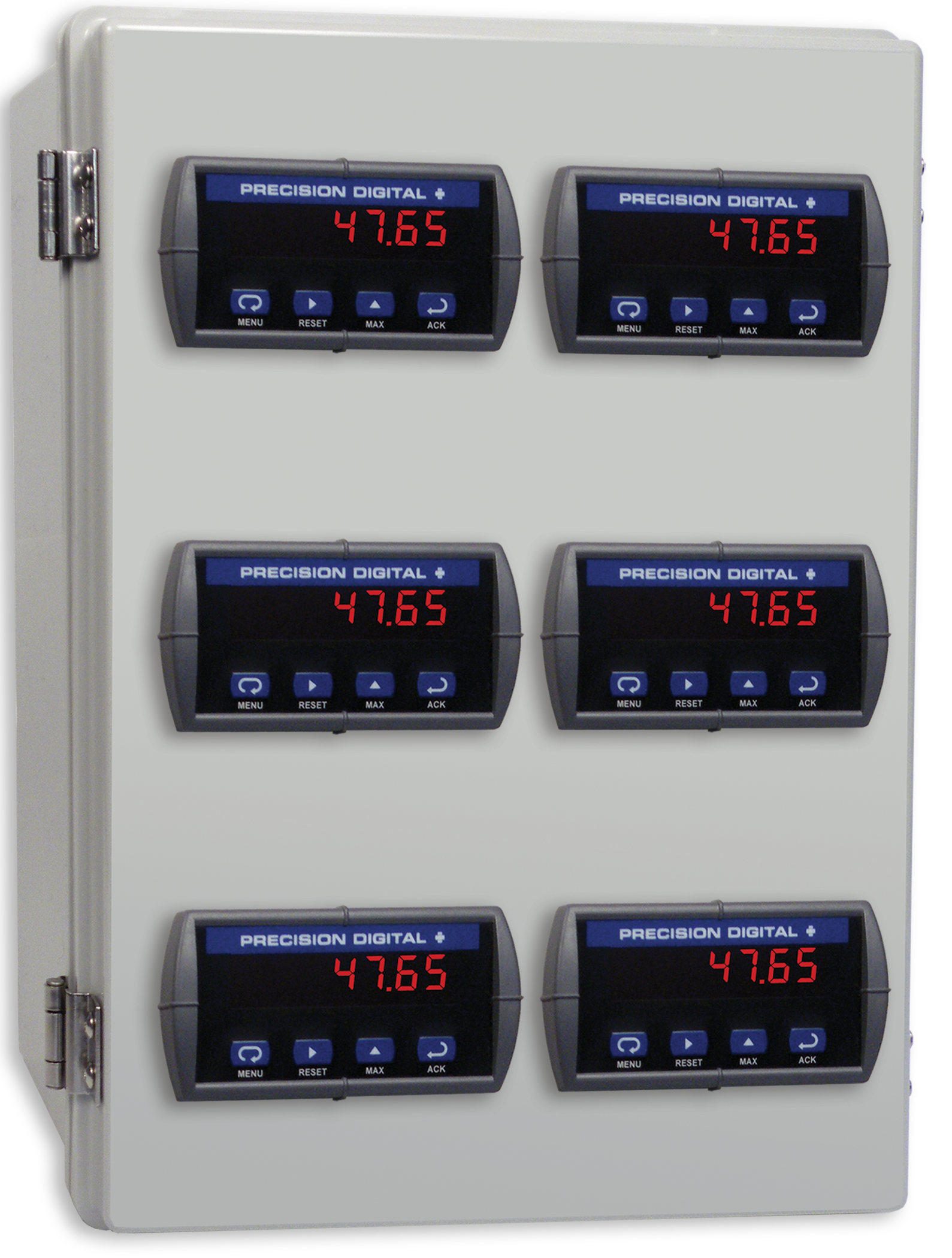
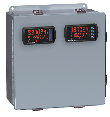
Plastic UL Type 4X Enclosure with (1) Vertical and (1) Horizontal 1/8 DIN Cutouts
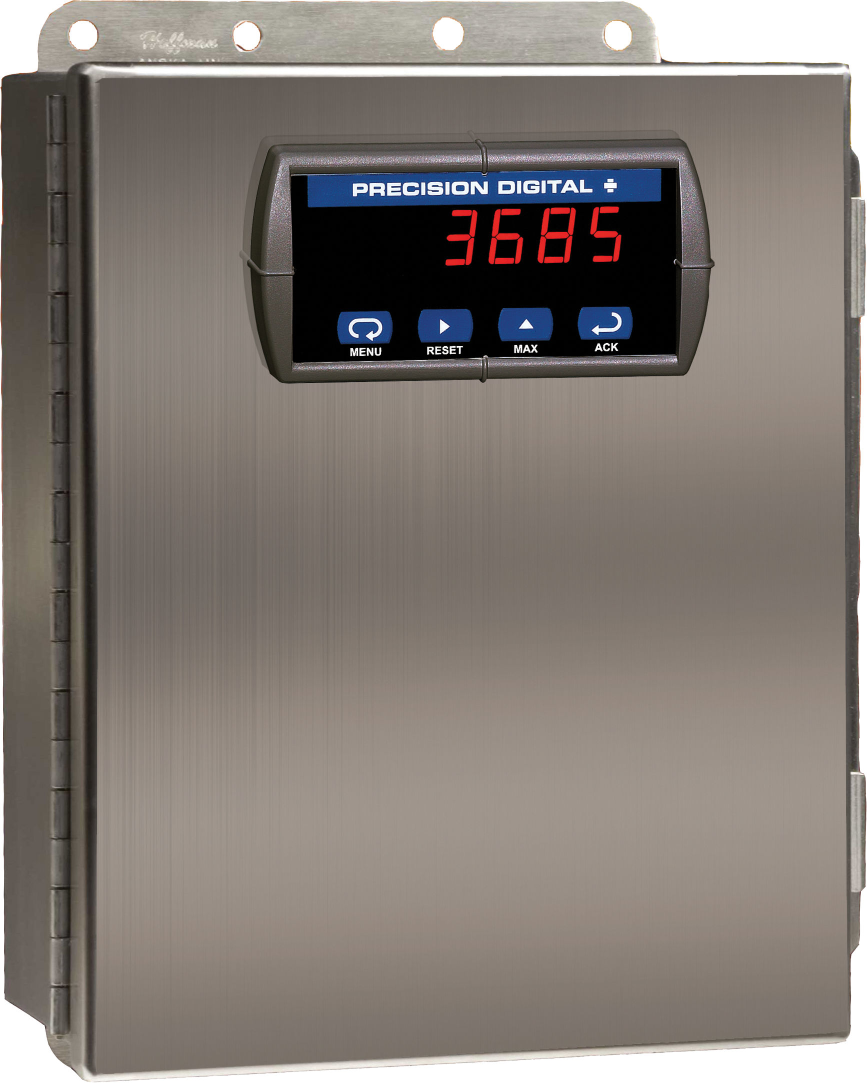

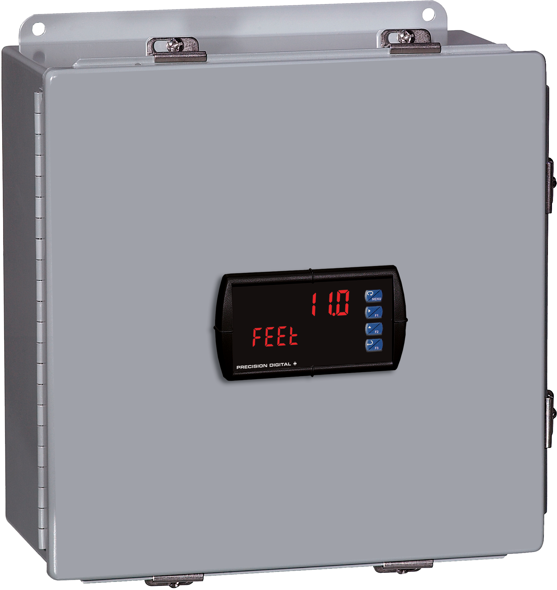
PDA2604-1C
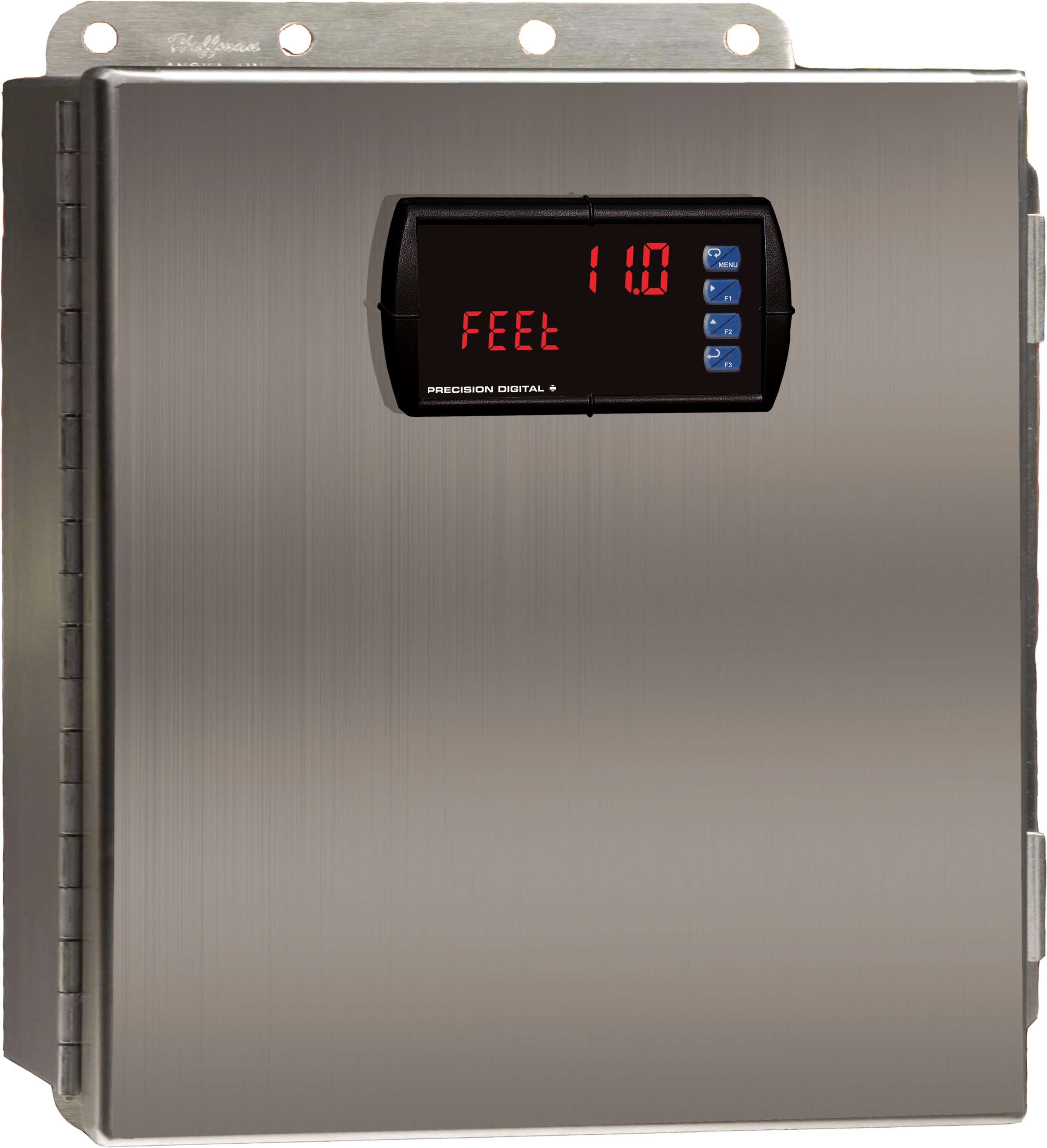
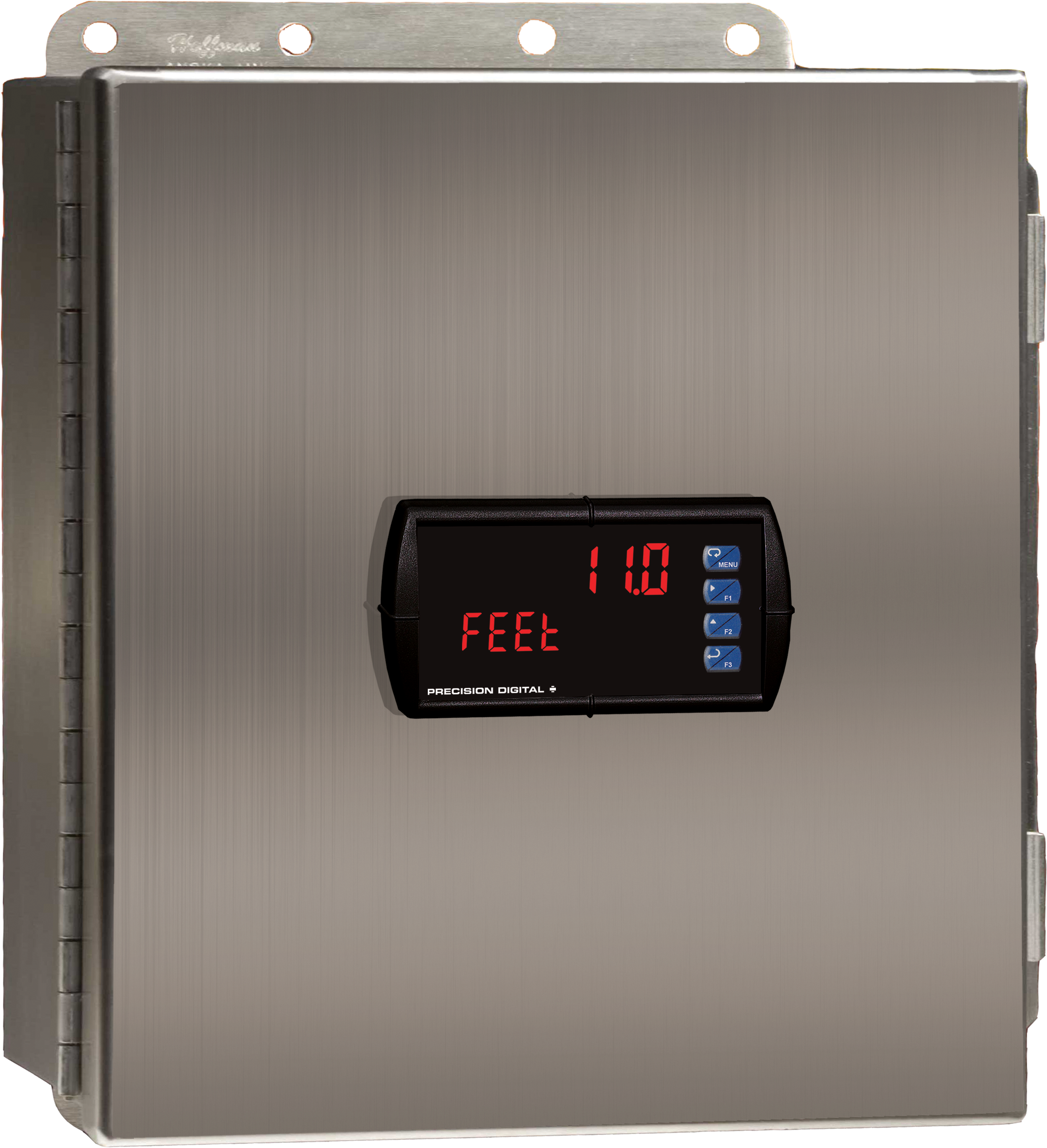
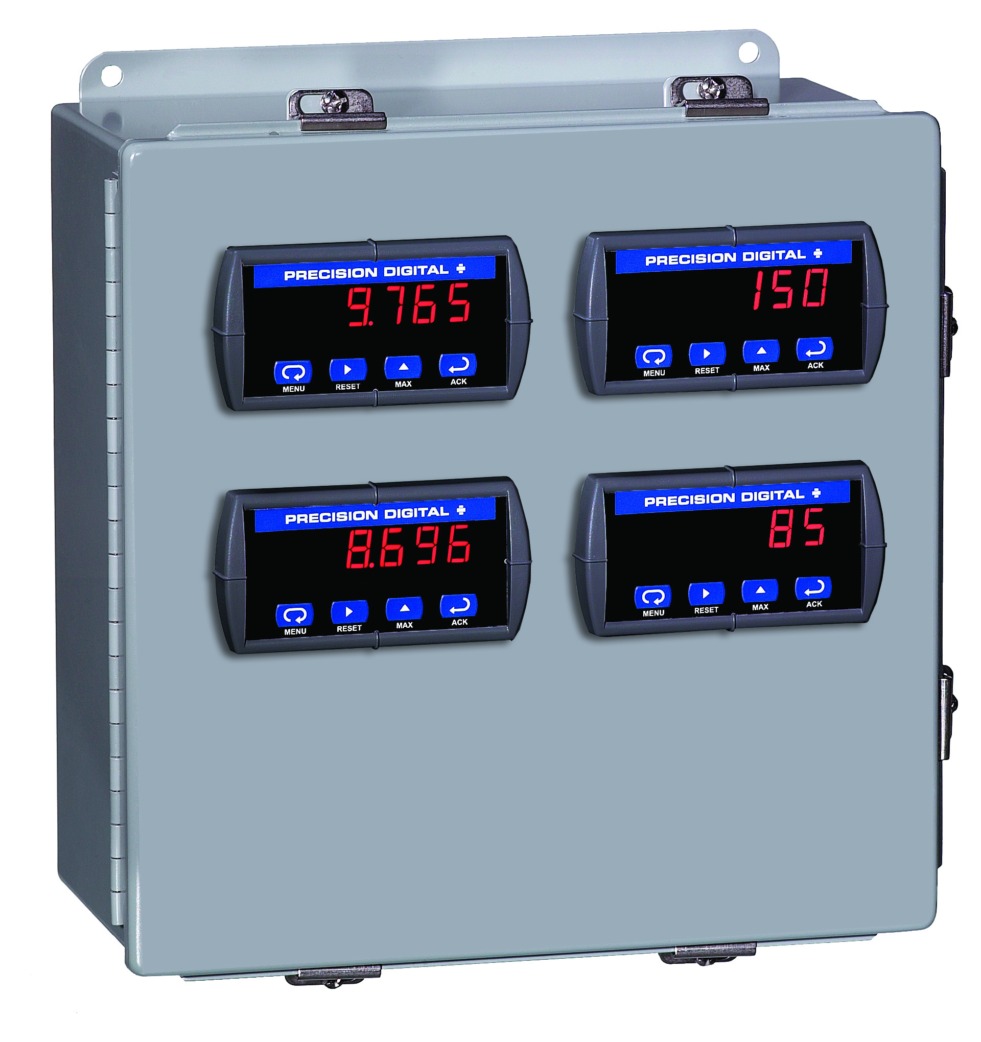
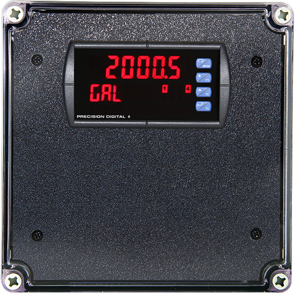
Stainless Steel UL Type 4X Enclosure with (1) Centered Horizontal 1/8 DIN Cutout
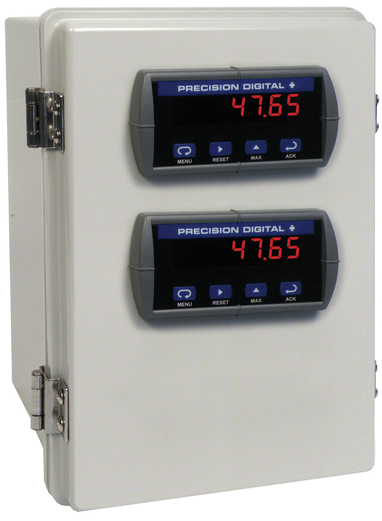
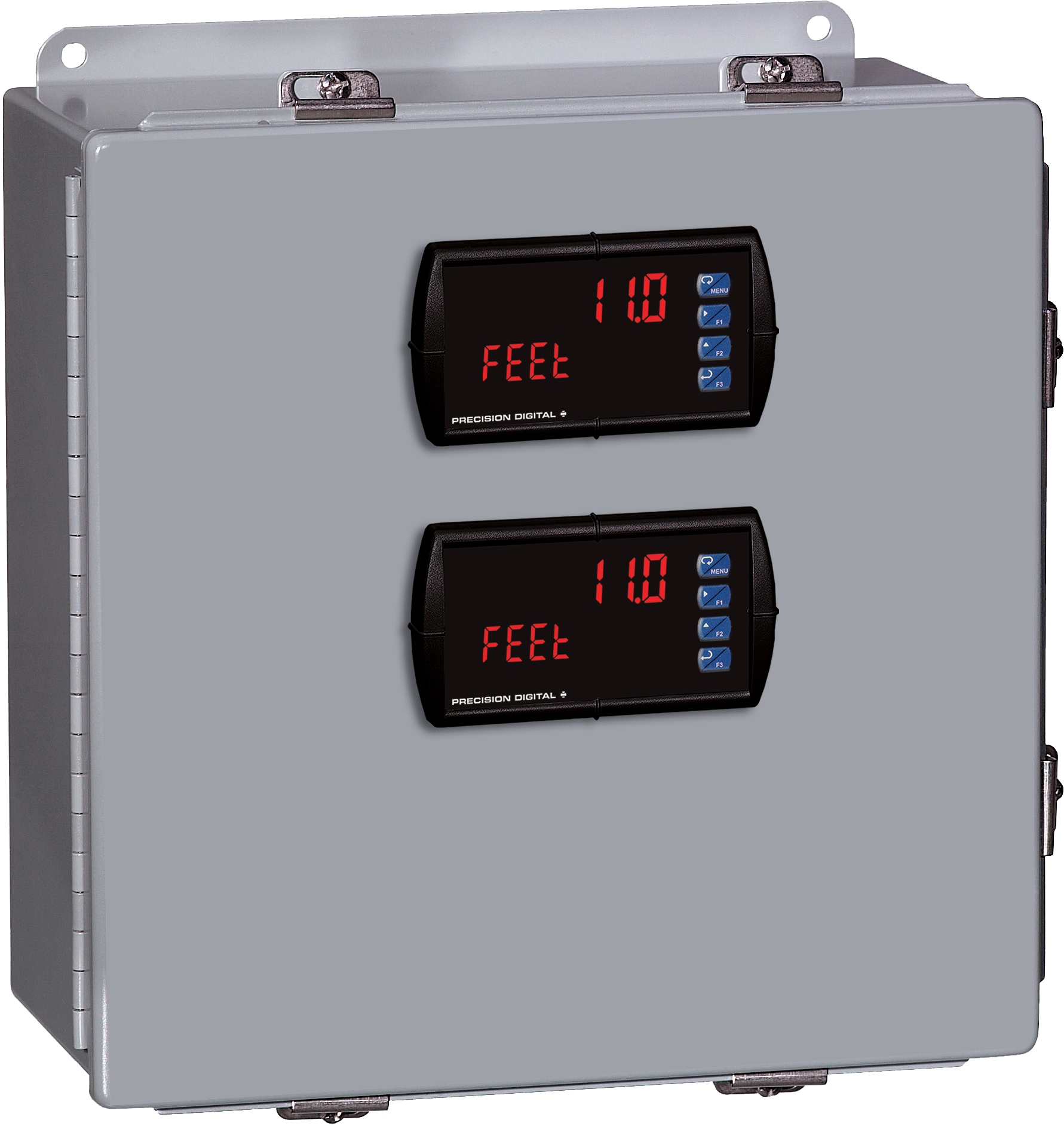
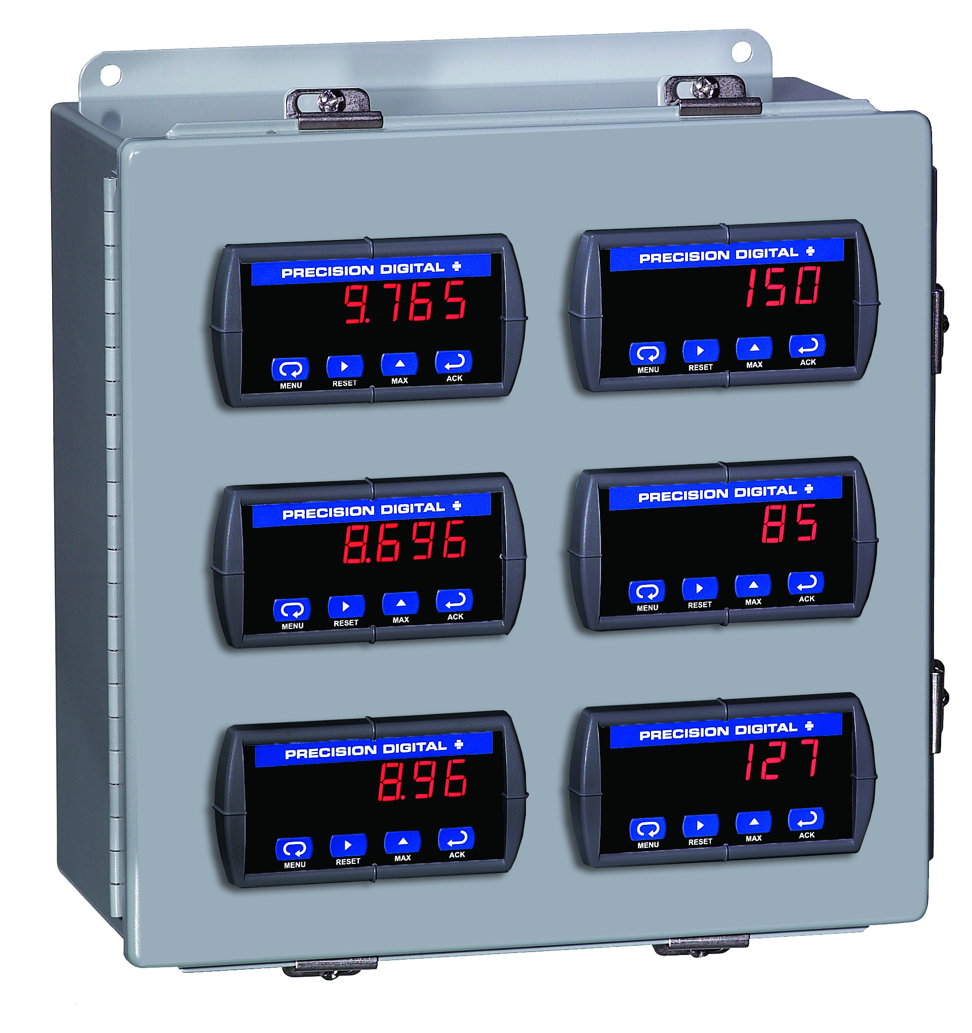
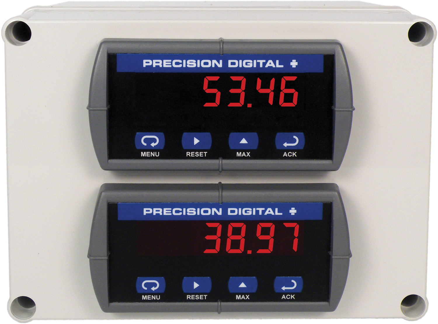
PDA2604-2C
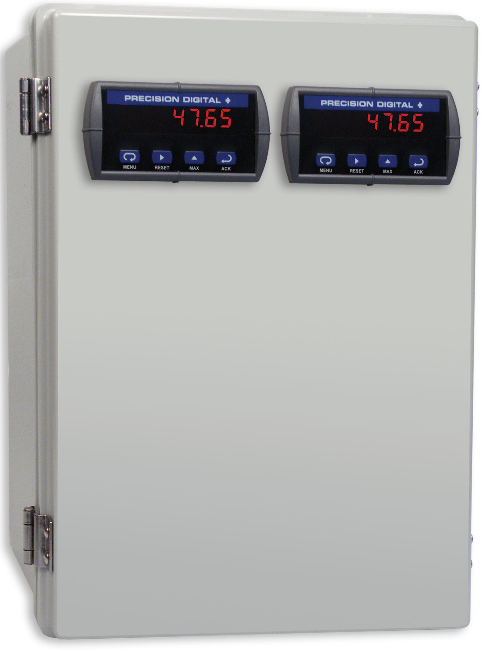
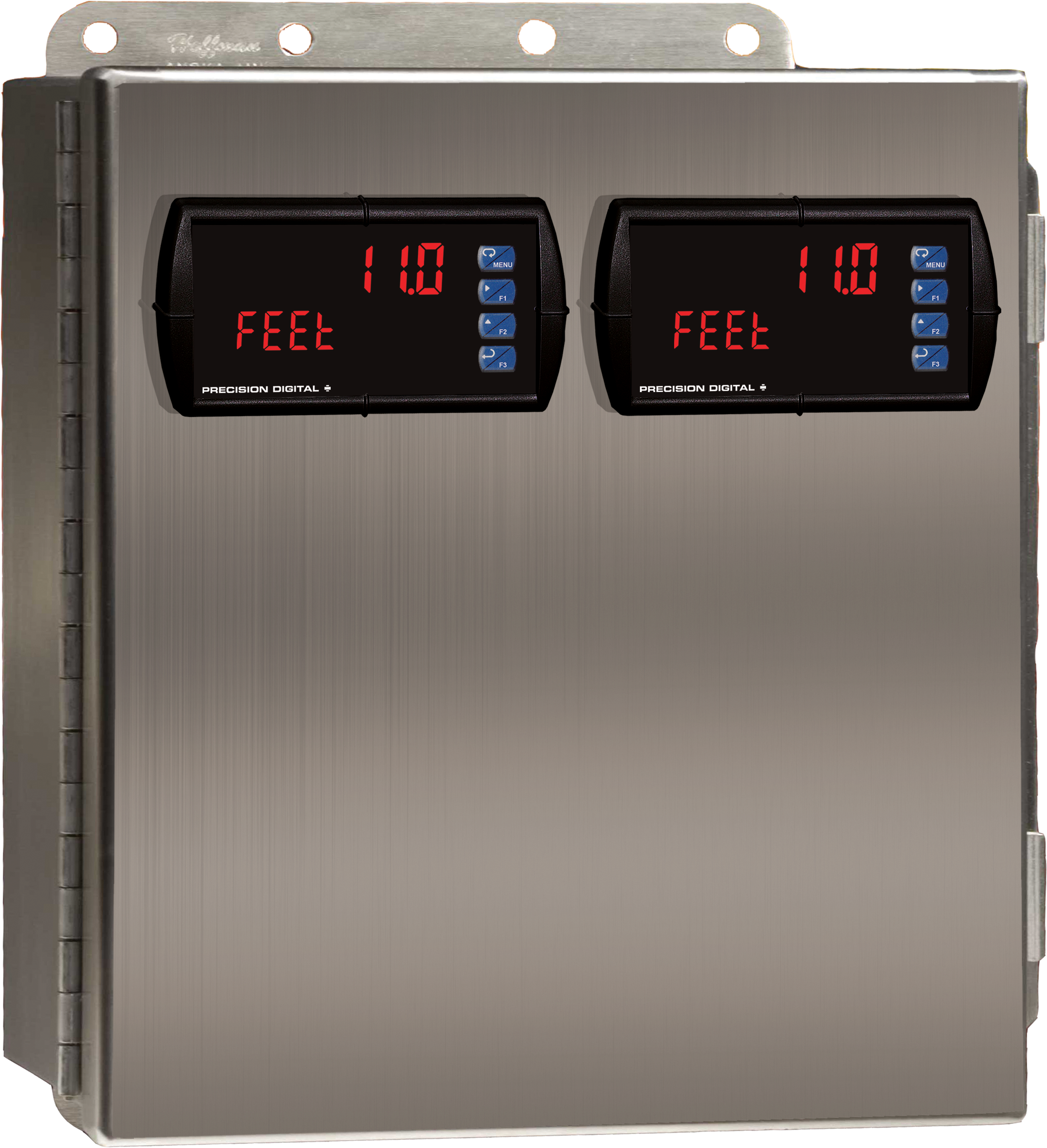
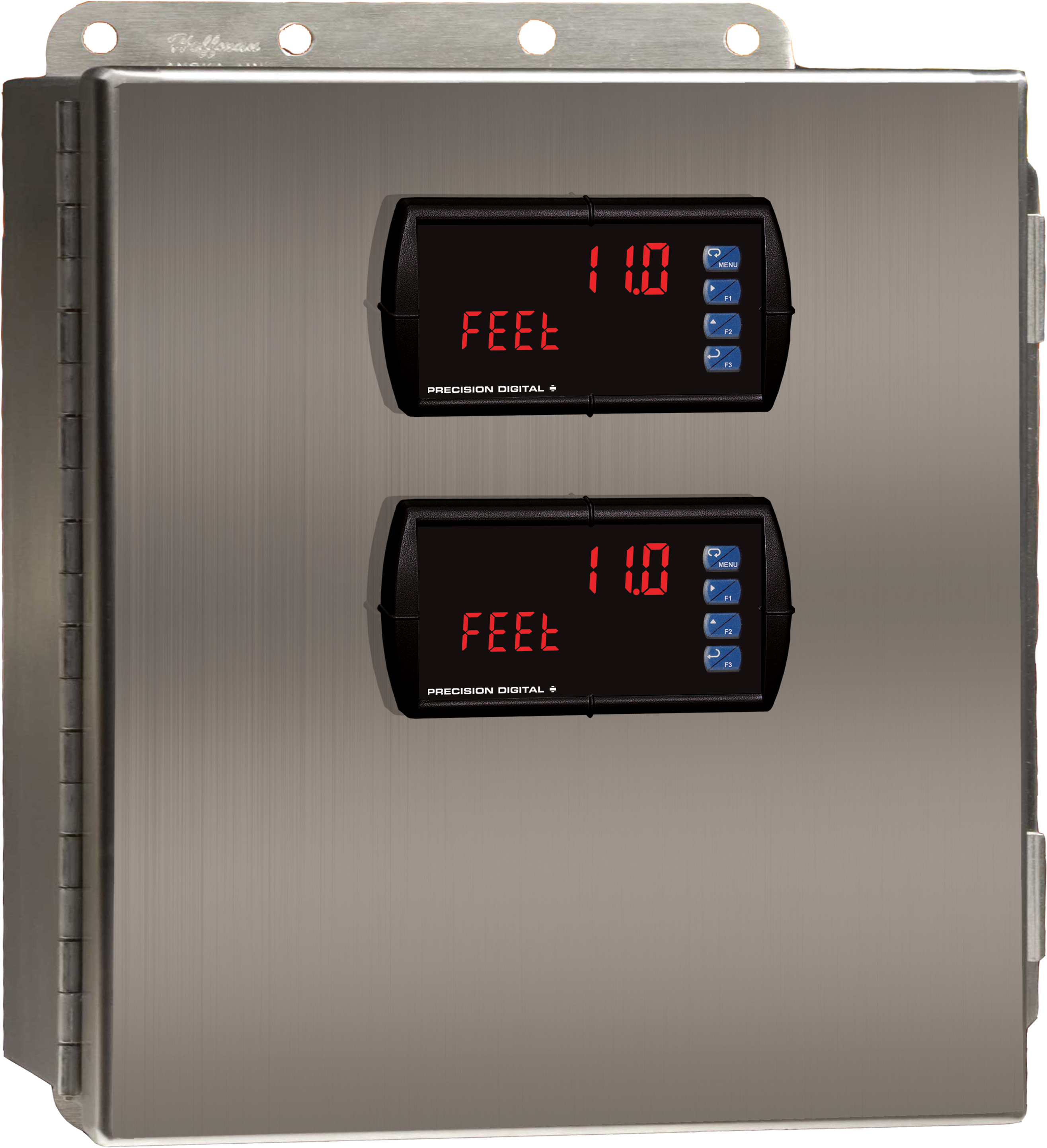
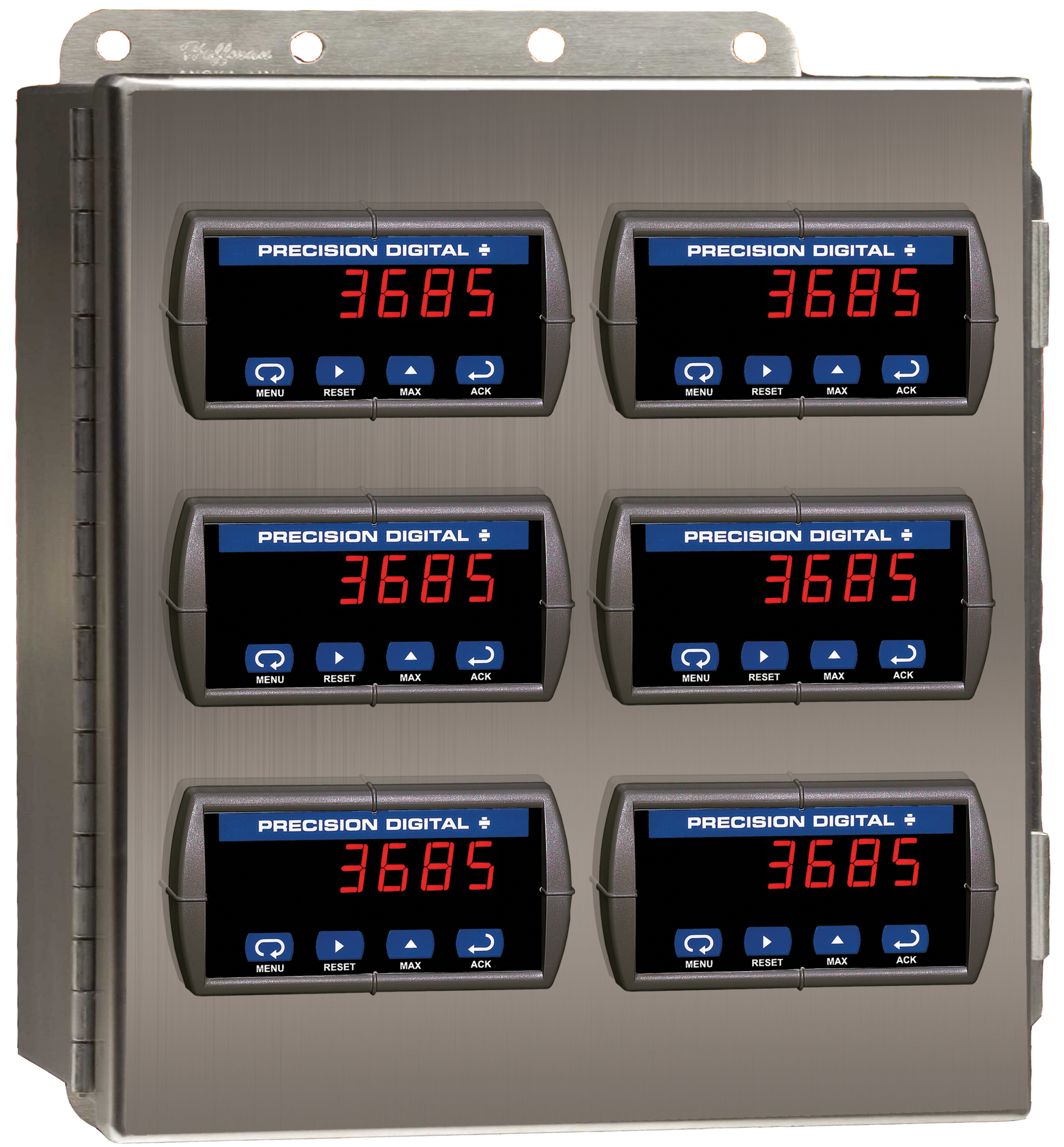
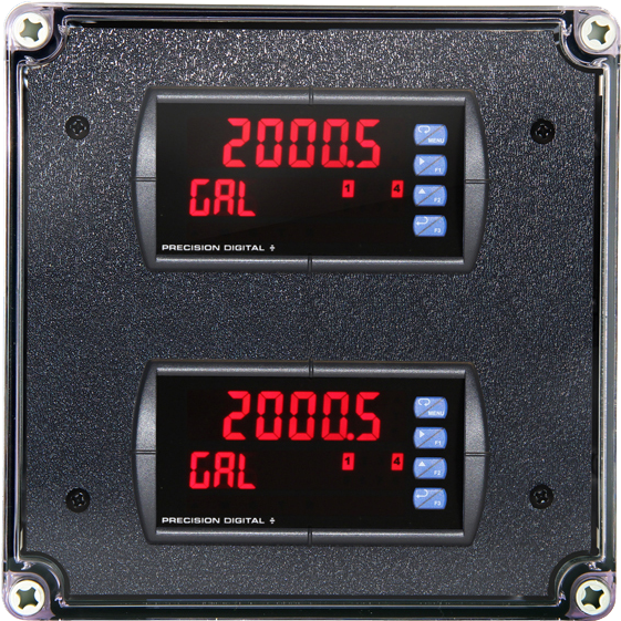
Stainless Steel UL Type 4X Enclosure with (2) Centered Horizontal 1/8 DIN Cutouts
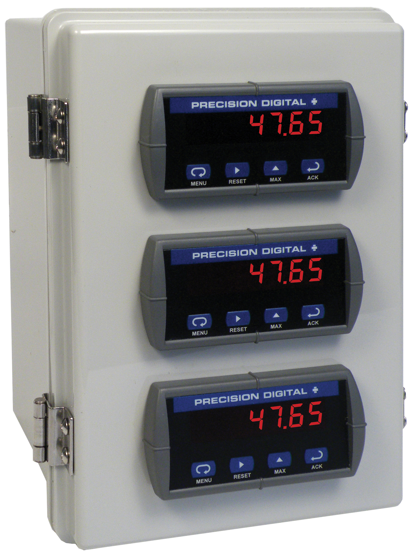
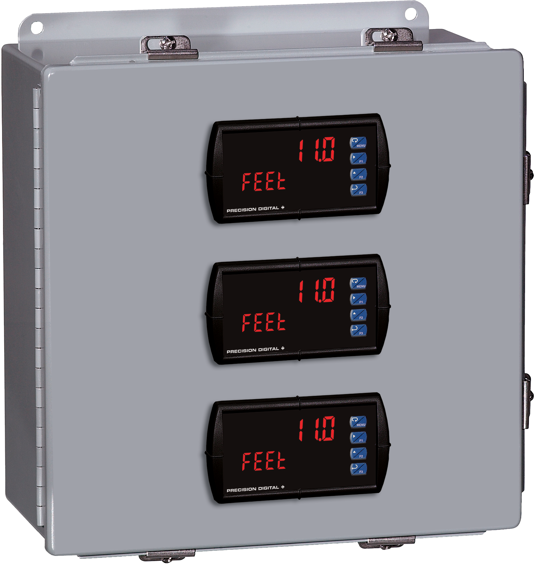
PDA2604-3C
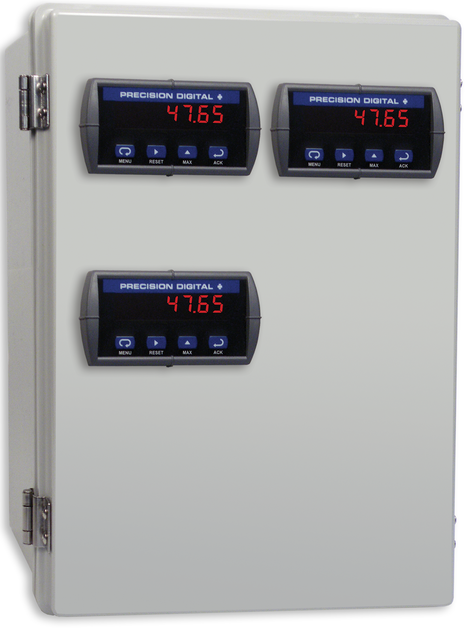
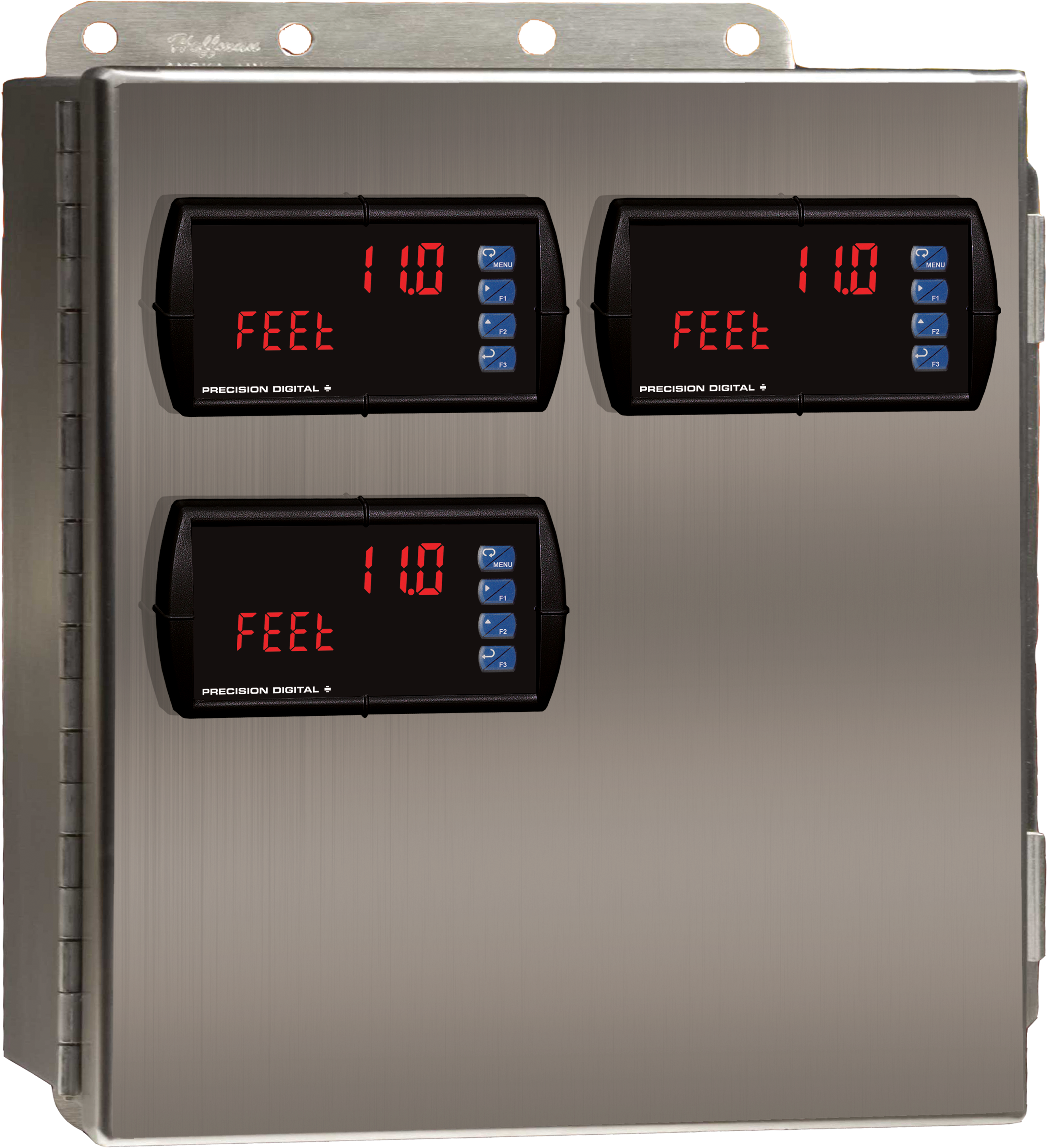
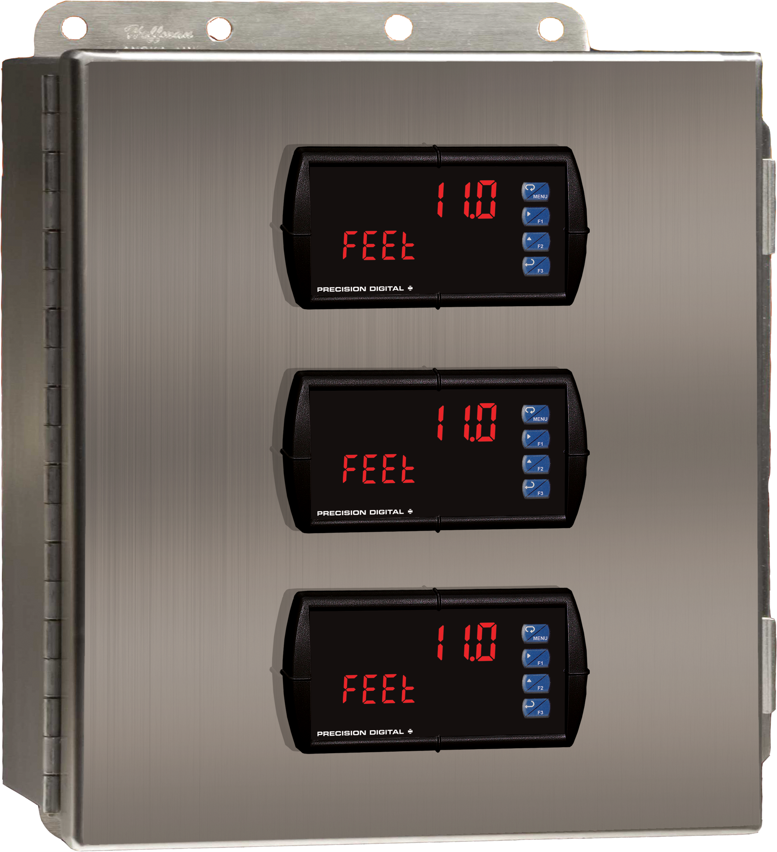
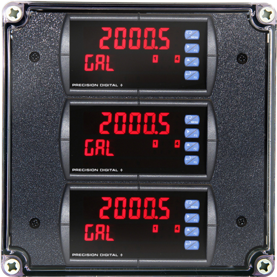
Stainless Steel UL Type 4X Enclosure with (3) Centered Horizontal 1/8 DIN Cutouts

PDA2622
Stainless Steel UL Type 4X Enclosure with (1) Vertical and (1) Horizontal 1/8 DIN Cutouts


PDA2821
Plastic UL Type 4X Enclosure with (1) Vertical and (1) Horizontal 1/8 DIN Cutouts
PDA3414
Plastic UL Type 4X Enclosure with (1) Vertical and (1) Horizontal 1/8 DIN Cutouts