Except where noted all specifications apply to operation at +25°C.
General
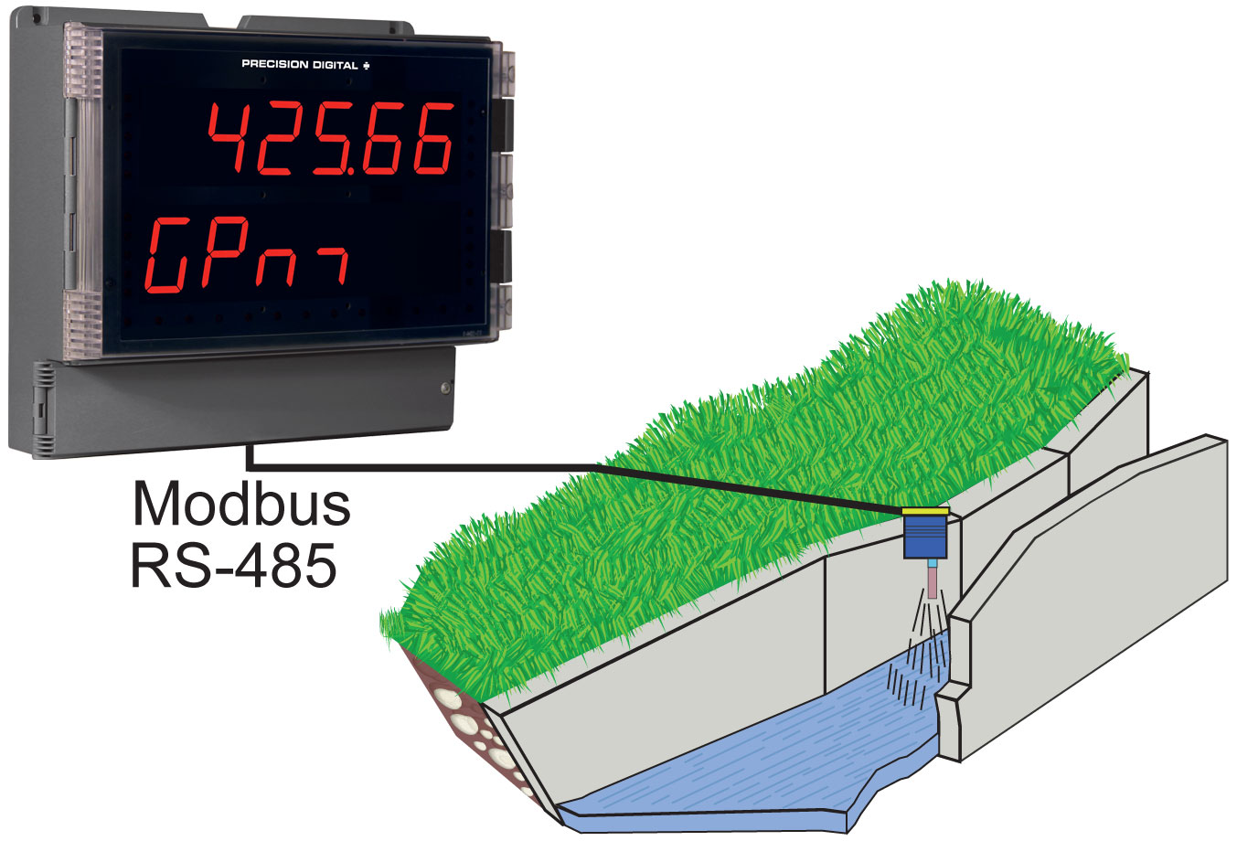
Input/Output:Modbus RTU over RS-485, Two analog inputs (4-20 mA, ±10 V)
Display: Two lines with 1.8" (46 mm) high digits, red LEDs; 6 digits per line (-99999 to 999999), with lead zero blanking
Display Intensity Eight user selectable intensity levels
Display Update Rate: 5/second (200 ms)
Overrange: Display flashes 999999
Underrange: Display flashes -99999
Programming Methods: Four programming buttons, digital inputs, PC and ScanView software, or Modbus registers.
Max/Min Display: Max/min readings reached by the process are stored until reset by the user or until power to the meter is turned off.
Password: Three programmable passwords restrict modification of programmed settings.
Pass 1: Allows use of function keys and digital inputs
Pass 2: Allows use of function keys, digital inputs and editing set/reset points
Pass 3: Restricts all programming, function keys, and digital inputs.
Power Options: 85-265 VAC 50/60 Hz, 90-265 VDC, 20 W max or 12-24 VDC ± 10%, 15 W max. Powered over USB for configuration only.
Isolated Transmitter Power Supply: Terminals P+ & P-: 24 VDC ± 10%. 12-24 VDC powered models selectable for 24, 10, or 5 VDC supply (internal P+/P- switch). 85-265 VAC models rated @ 200 mA max, 12-24 VDC powered models rated @ 100 mA max, @ 50 mA max for 5 or 10 VDC supply.
Non-Volatile Memory: All programmed settings are stored in non-volatile memory for a minimum of ten years if power is lost.
Fuse: Required external fuse: UL Recognized, 5 A max, slow blow; up to 6 meters may share one 5 A fuse
Isolation: 4 kV input/output-to-power line; 500 V input-to-output or output-to-P+ supply
Overvoltage Category: Installation Overvoltage Category II: Local level with smaller transient overvoltages than Installation Overvoltage Category III.
Environmental: Operating temperature range: -40 to 150°F (-40 to 65°C); Storage temperature range: -40 to 185°F (-40 to 85°C); Relative humidity: 0 to 90% non-condensing
Connections: Removable and integrated screw terminal blocks accept 12 to 22 AWG wire.
Enclosure: UL Type 4X, IP65 rated. Polycarbonate & glass blended plastic case, color: gray. Includes four PG11 through-hole conduit openings, with two factory installed PG11, IP68, black nylon threaded hole plugs with backing nuts.
Wall Mounting: Four (4) mounting holes provided for mounting meter to wall.
Pipe Mounting: Optional pipe mounting kit (PDA6260) allows for pipe mounting. Sold separately.
See PD2-6080/81 manual for instructions.Tightening Torque: Removable Screw Terminals: 5 lb-in (0.56 Nm);
Digital I/O and RS485 Terminals: 2.2 lb-in (0.25 Nm)
Overall Dimensions: 10.63" x 12.59" x 4.77" (270 mm x 319.7 mm x 121.2 mm) (H x W x D)
Weight: 6.10 lbs (2.76 kg)
UL File Number: UL & C-UL Listed. E160849; 508 Industrial Control Equipment.
Warranty: 3 years parts & labor
USB Connection: Compatibility: USB 2.0 Standard, Compliant
Connector Type: Micro-B receptacle
Cable: USB A Male to Micro-B Cable
Driver: Windows 98/SE, ME, 2000, Server 2003/2008, XP 32/64-Bit, Vista 32/64-Bit, Windows 7 32/64-Bit, Windows 10 32/64-Bit
Power: USB Port
Operating Modes
Master: Processes data read from Modbus RTU slave devices. It polls up to 16 process variables from 1 to 16 slave devices. The Master is capable of scanning the selected PVs, scaling the data, triggering relays, performing math operations, and driving the analog outputs.
Snooper: Listens to the Modbus traffic and picks up a specific register or registers being polled by a master device from a specific slave device and processes the data being read. The Snooper mode handles the data the same way as the Master.
Slave: Processes data sent to it from a Modbus RTU master device.
Note: The relays and the 4-20 mA outputs are functional in all modes.
Master & Snooper Settings
PV Number: PV1–PV16 Enable or disable the process variables to be polled by the Master.
Slave Id: Assign the slave ID or address (1-247, 256-259 for mA or volts inputs) containing the process variables to be displayed by the selected PV.
Function Code: Select which Modbus function code (03, 04, or 65) to use in reading the slave device.
Register Number: 5 digit: 30001-39999, 40001-49999, or 1-65,536
6 digit: 300001-365536 or 400001-465536 (Function Code 65 N/A here)
Specifies which register(s) to read in the slave device. Range is dependent on Function Code selection (65, 04, or 03) and digits selection (5 or 6).
Data Type: Select the data format that the slave device uses. Select between Short integer (2 byte), Long integer (4 byte), or floating point (4 byte), Signed or Unsigned (integer only) and byte order: 1234, 4321, 2143, or 3412 (big-endian vs. little-endian, or swapped).
Poll Time: 1.0 to 99.9 sec. Time between read-commands (Master mode).
Slave Response Timeout: 0.0 to 99.9 seconds: Time allowed for the slave to respond before the scanner generates a communication break condition. The master polls the slave 3 times before starting the response timeout timer.
Slave/Snooper mode: Time the scanner will wait for new data before going into break condition.
Slave mode: Programming 0 disables the timeout; the last value received will be displayed indefinitely.
Communication Break:Displays "brEAK" after the Master has polled the slave device 3 times and the response timeout has elapsed. The Snooper and Slave modes go into break condition after no new data is received within the response timeout window. Relays can be programmed to go on, off, or ignore the break condition. The analog outputs can be setup to generate a fixed mA current when a break condition is detected.
PV Settings
Tag & Units: 6-character, independent tag and units for each PV and math channel
PV Format: PD6080 default: Decimal format
PD6081 default: FT & IN, 1/8th or 1/16th; decimal format may be selected for display line 2 indication.
Display Decimal Point: Up to five decimal places or none: d.ddddd, dd.dddd, ddd.ddd, dddd.dd, ddddd.d, or dddddd
Float Decimal Point:Select the number of decimals to use for the floating point data expected from the slave or master device (this is independent from the display decimal point selection).
PV & Math Scaling: All PVs and math channels may be scaled to represent the input data in any engineering unit.
Example: Level transmitter = 999.999 inches; to display in Ft-In-1/16th scale input 2 to display 83 Ft – 4 In – 0/16th.
Display Settings
Scan Mode: Automatic: 1.0 to 99.9 sec
Manual: Front panel or digital inputs
Go on alarm: Continues scanning after an alarm is detected
Stop on alarm: Goes to the alarmed PV and stops scanning; press Scan to resume scanning.
Display Scan Rate: Master/Snooper: 1 PV/second to 1 PV every 99.9 seconds
Slave: Dependent on master device (e.g. PLC)
Note: The display scan rate is independent of the poll time.
Display Assignment: Display line 1 may be assigned to PV (process values), Ch C (math channel), PV & units, tag & PV, tag-PV-units, C & units, tag-C-unit, Set point 1 8, max/min PV, max/min C.
Display line 2 may be assigned to all of the above, tag, tag & units, or off.
The tag and units are displayed alternately for 2 sec max, when selected.
Different tags & PVs may be selected to display on line 1 and line 2 at the same time.
Math Functions
| Name | Math Operation (Examples) (P = Adder, F = Factor) | Setting |
| Addition | (PV1+PV2+P)*F | Sunm |
| Difference | (PV1-PV2+P)*F | diF |
| Absolute diff. | ((Abs(PV1- PV2)+P)*F | diFAbS |
| Average | (((PV1+PV2)/2)+P)*F | AvG |
| Multiplication | ((PV1*PV2)+P)*F | Nmulti |
| Division | ((PV1/PV2)+P)*F | divide |
| Max PV | Max value of all selected PVs | Hi-pv |
| Min PV | Min value of all selected PVs | Lo-pv |
| Draw | ((PV1/PV2)-1)*F | drAuw |
| Weighted avg. | ((PV2-PV1)*F)+PV1 | uwavg |
| Ratio | (PV1/PV2)*F | ratio |
| Concentration | (PV1/(PV1+PV2))*F | Concen |
| Math 2 | Math on other math channels | Nmath2 |
Programmable Constants:Constant P (Adder): -99.999 to 999.999, default: 0.000;
Constant F (Factor): 0.001 to 999.999, default: 1.000
Serial Communications
Compatibility: EIA-485
Connectors:Removable screw terminal connector
Max Distance:3,937' (1,200 m) max
Status Indication:Separate LEDs for Power (P), Transmit (TX), and Receive (RX)
Scanner Id:1 – 247 (Scanner Modbus address)
Baud Rate:300 – 19,200 bps
Transmit Time Delay:Programmable 0 to 4999 ms
This is the time the scanner will wait for a slave to respond before sending another request on the bus. This value should be greater than 100 ms to avoid collisions on the bus.
Data:8 bits (1 start bit, 1 or 2 stop bits)
Parity:Even, Odd, or None with 1 or 2 stop bits
Byte-To-Byte Timeout:0.01 – 2.54 second
Turn Around Delay:Less than 2 ms (fixed)
Note: Refer to the Modbus® Scanner Modbus Register Tables located at www.predig.com.Relays
Rating: 4 SPDT (Form C) internal rated 3 A @ 30 VDC and 125/250 VAC resistive load; 1/14 HP (≈ 50 W) @ 125/250 VAC for inductive loads
Noise Suppression: Noise suppression is recommended for each relay contact switching inductive loads. See manual for details.
Electrical Noise
Suppression: A suppressor (snubber) should be connected to each relay contact switching inductive loads to prevent disruption to the microprocessor's operation. Recommended suppressor value: 0.01 µF/470 , 250 VAC (PDX6901).
Deadband: 0-100% of span, user programmable
High Or Low Alarm: User may program any alarm for high or low trip point. Unused alarm LEDs and relays may be disabled (turn off).
Relay Operation: Automatic (non-latching) and/or manual reset Latching (requires manual acknowledge) with/without clear Pump alternation control (2 to 4 relays) Sampling (based on time) Off (disable unused relays and enable Interlock feature) Manual on/off control mode
Relay Reset: User selectable via front panel buttons or digital inputs
1. Automatic reset only (non-latching), when the input passes the reset point.
2. Automatic + manual reset at any time (non-latching)
3. Manual reset only, at any time (latching)
4. Manual reset only after alarm condition has cleared (latching)
Note: Front panel button or digital input may be assigned to acknowledge relays programmed for manual reset.Time Delay: 0 to 999.9 seconds, on & off relay time delays; Programmable and independent for each relay
Fail-Safe Operation: Programmable and independent for each relay.
Note: Relay coil is energized in non-alarm condition. In case of power failure, relay will go to alarm state.Auto Initialization: When power is applied to the meter, relays will reflect the state of the input to the meter.
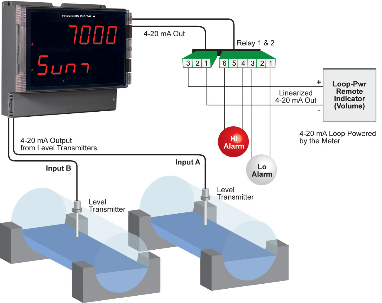
Isolated 4-20 mA Transmitter Output
Output Source: Input channels A or B, rate, total, or grand total; channel C; max or min for channel A or B; highest or lowest max or min of A and B; set points 1-4; Modbus input; or manual control mode
Scaling Range: 1.000 to 23.000 mA for any display range
Calibration: Factory calibrated: 4.000 to 20.000 = 4-20 mA output
Analog Out Programming: 23.000 mA maximum for all parameters: Overrange, underrange, max, min, and break
Accuracy: ± 0.1% of span ± 0.004 mA
Temperature Drift: 0.4 μA/°C max from 0 to 65°C ambient, 0.8 μA/°C max from -40 to 0°C ambient
Note: Analog output drift is separate from input drift.Isolated Transmitter Power Supply: Terminals I+ & R: 24 VDC ± 10%. Isolated from the input at >500 V. May be used to power the 4-20 mA output or other devices. All models rated @ 40 mA max.
Output Loop Resistance:| Power supply | Minimum | Maximum |
| 24 VDC | 10 Ω | 700 Ω |
| 35 VDC (external) | 100 Ω | 1200 Ω |
Dual Process Input
Two Inputs Two
non-isolated inputs, each separately field selectable: 0-20, 4-20 mA, 10 V (0-5, 1-5, 0-10 V), Modbus PV (Slave)
PV Analog Channel Id: Ch-A mA: Assign PV to ID 256 or Ch-A volt: 257;
Ch-B mA: Assign PV to ID 258 or Ch-B volt: 259
Accuracy ±0.03% of calibrated span ±1 count, square root & programmable exponent accuracy range: 10-100% of calibrated span
Temperature Drift: 0.005% of calibrated span/°C max from 0 to 65°C ambient, 0.01% of calibrated span/°C max from -40 to 0°C ambient
Signal Input Conditioning:Linear, square root, programmable exponent, or
round horizontal tank volume calculation
Multi-Point Linearization: 2 to 32 points for PV1 and PV2
Programmable Exponent: 1.0001 to 2.9999
Low-Flow Cutoff:0-999999 (0 disables cutoff function) for PV1 and PV2
Calibration Range:| Input Range | Minimum Span Input 1 & Input 2 |
| 4-20 mA | 0.15 mA |
| ±10 V | 0.01 V |
An error message will appear if the input 1 and input 2 signals are too close together.Input Impedance:Voltage ranges: greater than 500 kΩ
Current ranges: 50 - 100 Ω (depending on resettable fuse impedance)
Input Overload: Current input protected by resettable fuse, 30 VDC max.
Fuse resets automatically after fault is removed.
HART Transparency: Analog input will not interfere with existing HART communications on the wired 4-20 mA signal
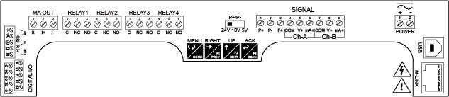
Digital Input & Output Terminal
Channels: 4 digital inputs & 4 digital outputs
Digital Input Logic High: 3 to 5 VDC
Digital Input Logic Low: 0 to 1.25 VDC
Digital Output Logic High: 3.1 to 3.3 VDC
Digital Output Logic Low: 0 to 0.4 VDC
Source Current: 10 mA maximum output current
Sink Current: 1.5 mA minimum input current
+5 V Terminal: To be used as pull-up for digital inputs only. Connect normally open pushbuttons across +5 V & DI 1-4.
WARNING! DO NOT use +5 V terminal to power external devices.