Except where noted all specifications apply to operation at +25°C.
General
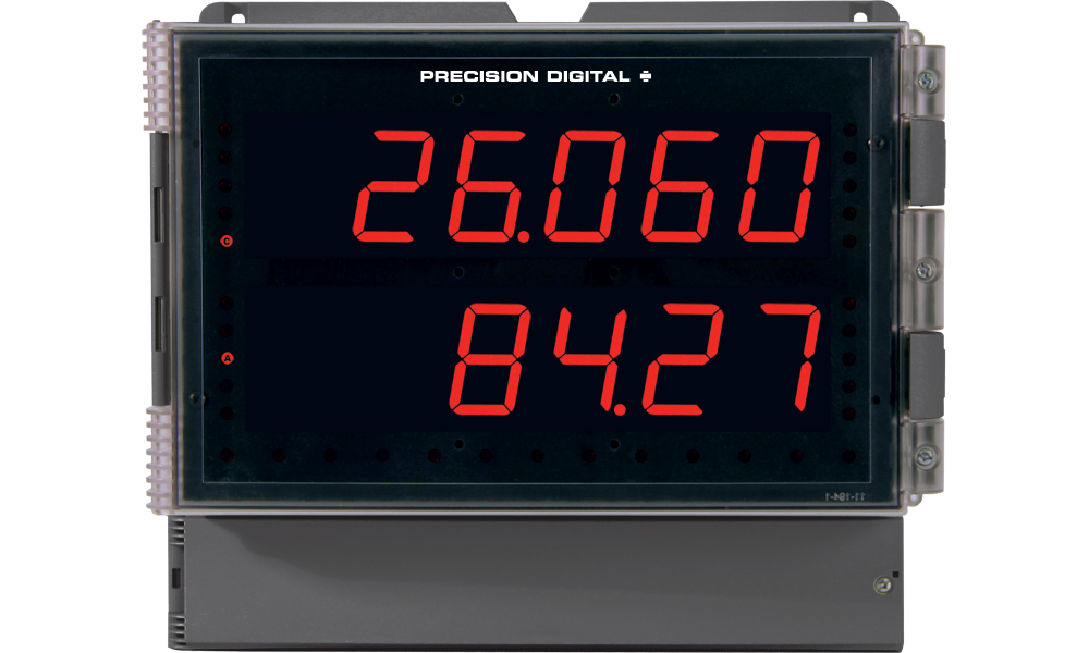
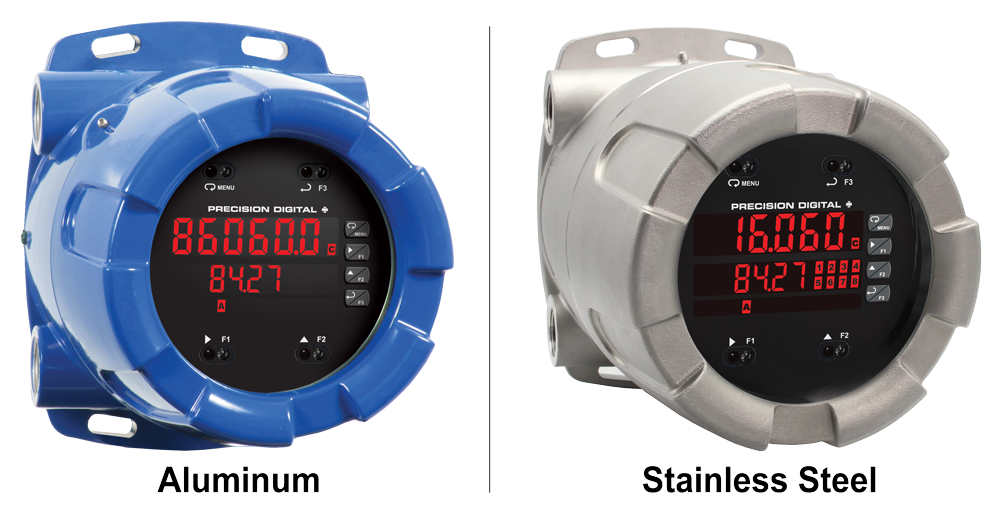
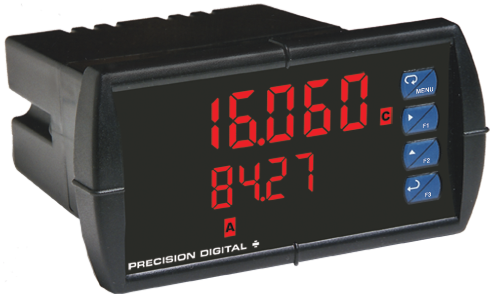
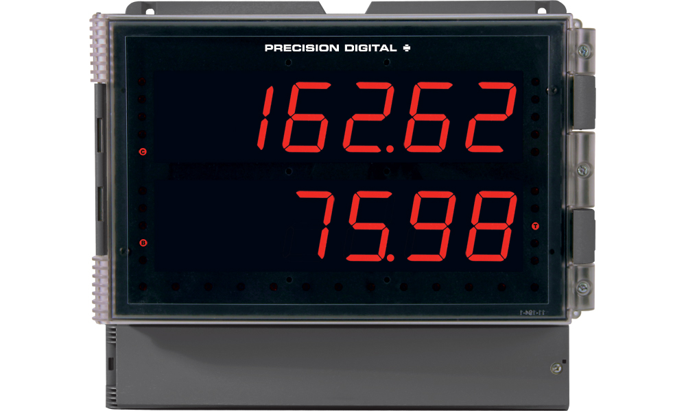
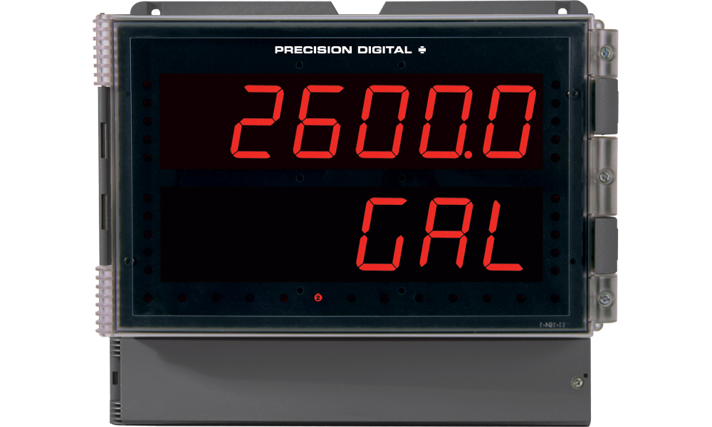
Display: Two lines with 1.8" (46 mm) high digits, red LEDs; 6 digits per line (-99999 to 999999), with lead zero blanking
Display Intensity Eight user selectable intensity levels
Display Update Rate: 5/second (200 ms)
Overrange: Display flashes 999999
Underrange: Display flashes -99999
Display Assignment: Display lines 1 & 2 may be assigned to process values for Channels A (Ch-A), B (Ch-B), or C (Ch-C), toggle between (Ch-A & Ch-B, Ch-A & Ch-C, Ch-B & Ch-C, and Ch-A, Ch-B, & Ch-C), toggle between Channel & units, show channel gross value (no tare) or toggle net (tare) and gross values, show relay set points, max & min values, or Modbus input. The lower display may also be set to show engineering units or be off, with no display.
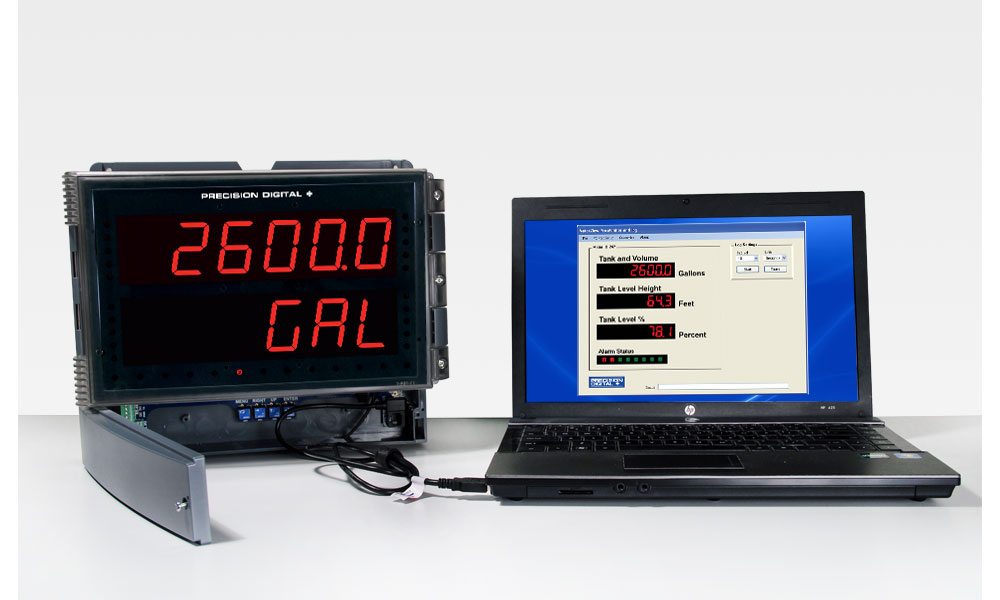
Programming Methods: Four programming buttons, digital inputs, PC and MeterView Pro software, or Modbus registers.
Noise Filter: Programmable from 2 to 199 (0 will disable filter)
Filter Bypass: Programmable from 0.1 to 99.9% of calibrated span
Recalibration: All ranges are calibrated at the factory. Recalibration is recommended at least every 12 months.
Max/Min Display: Max/min readings reached by the process are stored until reset by the user or until power to the meter is turned off.
Password: Three programmable passwords restrict modification of programmed settings.
Pass 1: Allows use of function keys and digital inputs
Pass 2: Allows use of function keys, digital inputs and editing set/reset points
Pass 3: Restricts all programming, function keys, and digital inputs.
Power Options: 85-265 VAC 50/60 Hz, 90-265 VDC, 20 W max or 12-24 VDC ± 10%, 15 W max. Powered over USB for configuration only.
Isolated Transmitter Power Supply: Terminals P+ & P-: 24 VDC ± 10%. 12-24 VDC powered models selectable for 24, 10, or 5 VDC supply (internal P+/P- switch). 85-265 VAC models rated @ 200 mA max, 12-24 VDC powered models rated @ 100 mA max, @ 50 mA max for 5 or 10 VDC supply.
Non-Volatile Memory: All programmed settings are stored in non-volatile memory for a minimum of ten years if power is lost.
Fuse: Required external fuse: UL Recognized, 5 A max, slow blow; up to 6 meters may share one 5 A fuse
Normal Mode Rejection: Greater than 60 dB at 50/60 Hz
Isolation: 4 kV input/output-to-power line; 500 V input-to-output or output-to-P+ supply
Overvoltage Category: Installation Overvoltage Category II: Local level with smaller transient overvoltages than Installation Overvoltage Category III.
Environmental: Operating temperature range: -40 to 150°F (-40 to 65°C); Storage temperature range: -40 to 185°F (-40 to 85°C); Relative humidity: 0 to 90% non-condensing
Connections: Removable and integrated screw terminal blocks accept 12 to 22 AWG wire.
Enclosure: UL Type 4X, IP65 rated. Polycarbonate & glass blended plastic case, color: gray. Includes four PG11 through-hole conduit openings, with two factory installed PG11, IP68, black nylon threaded hole plugs with backing nuts.
Wall Mounting: Four (4) mounting holes provided for mounting meter to wall.
Pipe Mounting: Optional pipe mounting kit (PDA6260) allows for pipe mounting. Sold separately.
See PD2-6060 manual for instructions.Tightening Torque: Removable Screw Terminals: 5 lb-in (0.56 Nm);
Digital I/O and RS485 Terminals: 2.2 lb-in (0.25 Nm)
Overall Dimensions: 10.63" x 12.59" x 4.77" (270 mm x 319.7 mm x 121.2 mm) (H x W x D)
Weight: 6.10 lbs (2.76 kg)
UL File Number: UL & C-UL Listed. E160849; 508 Industrial Control Equipment.
Warranty: 3 years parts & labor
USB Connection: Compatibility: USB 2.0 Standard, Compliant
Connector Type: Micro-B receptacle
Cable: USB A Male to Micro-B Cable
Driver: Windows 98/SE, ME, 2000, Server 2003/2008, XP 32/64-Bit, Vista 32/64-Bit, Windows 7 32/64-Bit, Windows 10 32/64-Bit
Power: USB Port
Dual Process Input
Two Inputs: Two
non-isolated inputs, each separately field selectable: 0-20, 4-20 mA, ±10 V (0-5, 1-5, 0-10 V), Modbus PV (Slave)
Channels: Channel A, Channel B, Channel C (Math channel)
Programmable Constants:Constant P (Adder): -99.999 to 999.999, default: 0.000;
Constant F (Factor): 0.001 to 999.999, default: 1.000
Math Functions:| Name | Function | Setting |
| Addition | (A+B+P)*F | Sunm |
| Difference | (A-B+P)*F | diF |
| Absolute diff. | ((Abs(A-B))+P)*F | diFAbS |
| Average | (((A+B)/2)+P)*F | AvG |
| Multiplication | ((A*B)+P)*F | nmulti |
| Division | ((A/B)+P)*F | divide |
| Max of A or B | ((AB-Hi)+P)*F | Hi-Ab |
| Min of A or B | ((AB-Lo)+P)*F | Lo-Ab |
| Draw | ((A/B)-1)*F | drAuw |
| Weighted avg. | ((B-A)*F)+A | uw avg |
| Ratio | (A/B)*F | ratio |
| Concentration | (A/(A+B))*F | Concen |
Note: The F constant can be any value from 0.001 to 999.999. If the value is less than 1, it will have the same effect as a divider. For example, the average could also be derived by using (A+B)*F, where F = 0.500.Sequence Of Operations For Input Programming:- Select Input for A and B
- Set up the engineering units for A, B, and C
- Set up decimal point for A, B, and C
- Program A & B
- Set up the displays for A, B, or C
- Select the transfer function for A & B (e.g. Linear)
- Select Math function for Channel C
- Program constants for Factor (F) and Adder (P)
- Program cutoff values for A and B
Accuracy: ±0.03% of calibrated span ±1 count, square root & programmable exponent accuracy range: 10-100% of calibrated span
Temperature Drift: 0.005% of calibrated span/°C max from 0 to 65°C ambient, 0.01% of calibrated span/°C max from -40 to 0°C ambient
Signal Input Conditioning: Linear, square root, programmable exponent, or round horizontal tank volume calculation
Multi-Point Linearization: 2 to 32 points for channel A and B
Programmable Exponent: 1.0001 to 2.9999
Round H Tank: Diameter & Length: 999.999 inch or cm calculates volume in gallons or liters respectively.
Low-Flow Cutoff: 0-999999 (0 disables cutoff function)
Decimal Point: Up to five decimal places or none: d.ddddd, d.dddd, d.ddd, d.dd, d.d, or dddddd
Calibration Range:| Input Range | Minimum Span Input 1 & Input 2 |
| 4-20 mA | 0.15 mA |
| ±10 V | 0.01 V |
An error message will appear if the input 1 and input 2 signals are too close together.Input Impedance: Voltage ranges: greater than 500 kΩ; Current ranges: 50 - 100 Ω (depending on resettable fuse impedance)
Input Overload: Current input protected by resettable fuse, 30 VDC max. Fuse resets automatically after fault is removed.
HART Transparency: Analog input will not interfere with existing HART communications on the wired 4-20 mA signal
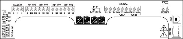
F4 Digital Input Contacts: 3.3 VDC on contact. Connect normally open contacts across F4 to COM.
F4 Digital Input Logic Levels: Logic High: 3 to 5 VDC, Logic Low: 0 to 1.25 VDC
Relays
Rating: 2 or 4 SPDT (Form C) internal and/or 4 SPST (Form A) external; rated 3 A @ 30 VDC and 125/250 VAC resistive load; 1/14 HP (≈ 50 W) @ 125/250 VAC for inductive loads
Noise Suppression: Noise suppression is recommended for each relay contact switching inductive loads. See manual for details.
Deadband: 0-100% of span, user programmable
High Or Low Alarm: User may program any alarm for high or low trip point. Unused alarm LEDs and relays may be disabled (turn off).
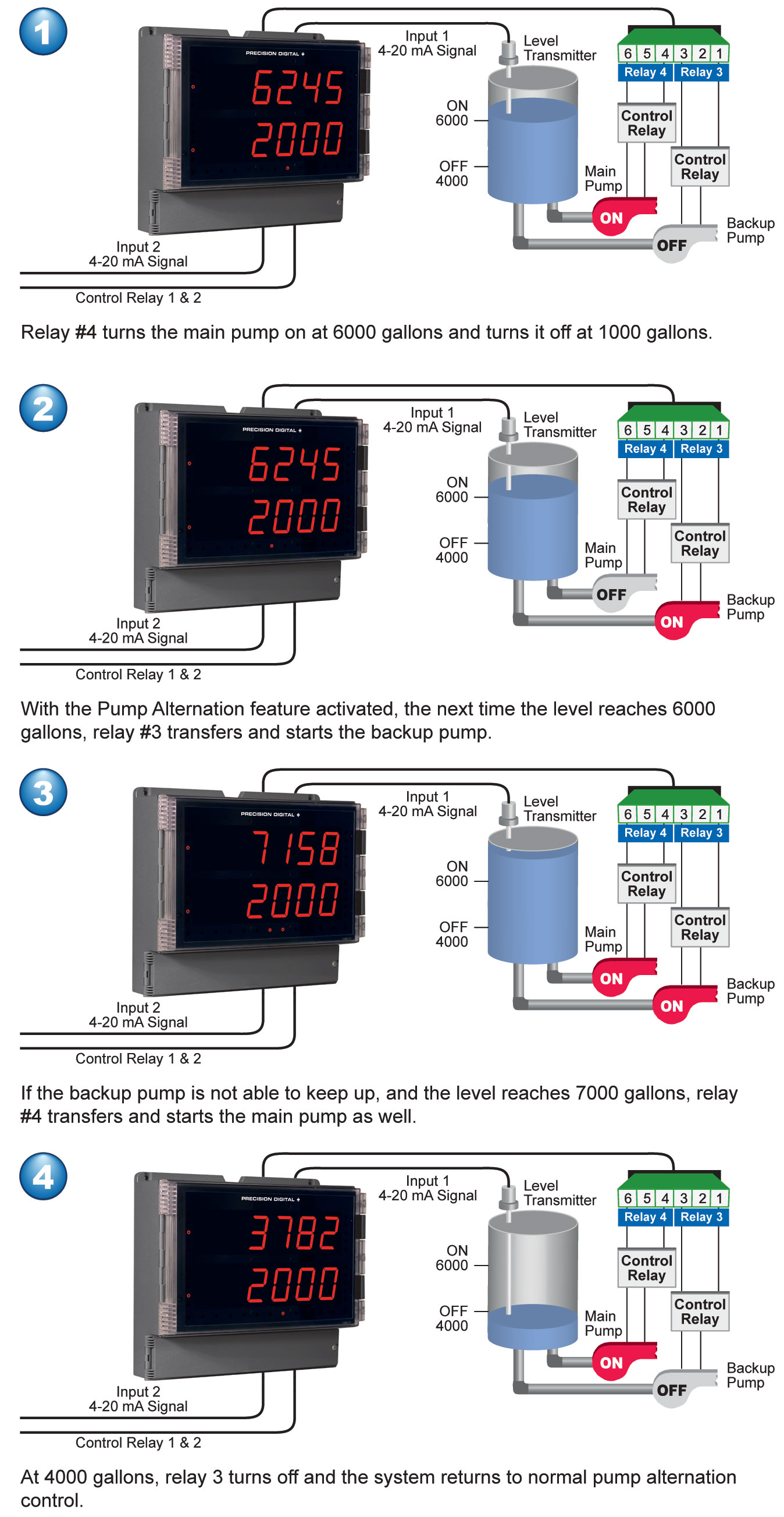
Relay Operation: Automatic (non-latching) and/or manual reset; Latching (requires manual acknowledge) with/without clear; Pump alternation control (2 to 4 relays); Sampling (based on time); Off (disable unused relays and enable Interlock feature); Manual on/off control mode
Relay Reset: User selectable via front panel buttons or digital inputs
1. Automatic reset only (non-latching), when the input passes the reset point.
2. Automatic + manual reset at any time (non-latching)
3. Manual reset only, at any time (latching)
4. Manual reset only after alarm condition has cleared (latching)
Note: Front panel button or digital input may be assigned to acknowledge relays programmed for manual reset.Time Delay: 0 to 999.9 seconds, on & off relay time delays; Programmable and independent for each relay
Fail-Safe Operation: Programmable and independent for each relay.
Note: Relay coil is energized in non-alarm condition. In case of power failure, relay will go to alarm
state.Auto Initialization: When power is applied to the meter, relays will reflect the state of the input to the meter.
Isolated 4-20 mA Transmitter Output
Output Source: Process variable (PV), max, min, set points 1-4, Modbus input, or manual control mode
Scaling Range: 1.000 to 23.000 mA for any display range
Calibration: Factory calibrated: 4.000 to 20.000 = 4-20 mA output
Analog Out Programming: 23.000 mA maximum for all parameters: Overrange, underrange, max, min, and break
Accuracy: ± 0.1% of span ± 0.004 mA
Temperature Drift: 0.4 µA/°C max from 0 to 65°C ambient, 0.8 µA/°C max from -40 to 0°C ambient
Note: Analog output drift is separate from input drift.Isolated Transmitter Power Supply: Terminals I+ & R: 24 VDC ± 10%. Isolated from the input at >500 V. May be used to power the 4-20 mA output or other devices. All models rated @ 40 mA max.
Output Loop Resistance:| Power supply | Minimum | Maximum |
| 24 VDC | 10 Ω | 700 Ω |
| 35 VDC (external) | 100 Ω | 1200 Ω |
RS485 Serial Communications Terminal
Compatibility: EIA-485
Connectors: Removable screw terminal connector
Max Distance: 3,937' (1,200 m) max
Status Indication: Separate LEDs for Power (P), Transmit (TX), and Receive (RX)
Modbus® RTU Serial Communications Protocol
Slave: ID 1 – 247 (Meter address)
Baud Rate: 300 – 19,200 bps
Transmit Time Delay: Programmable between 0 and 199 ms
Data: 8 bit (1 start bit, 1 or 2 stop bits)
Parity: Even, Odd, or None with 1 or 2 stop bits
Byte-To-Byte Timeout: 0.01 – 2.54 second
Turn Around Delay: Less than 2 ms (fixed)
Note: Refer to the Modbus Register Tables located at www.predig.com for details.Digital Input & Output Terminal
Channels: 4 digital inputs & 4 digital outputs
Digital Input Logic High: 3 to 5 VDC
Digital Input Logic Low: 0 to 1.25 VDC
Digital Output Logic High: 3.1 to 3.3 VDC
Digital Output Logic Low: 0 to 0.4 VDC
Source Current: 10 mA maximum output current
Sink Current: 1.5 mA minimum input current
+5 V Terminal: To be used as pull-up for digital inputs only. Connect normally open pushbuttons across +5 V & DI 1-4.
WARNING! DO NOT use +5 V terminal to power external devices.