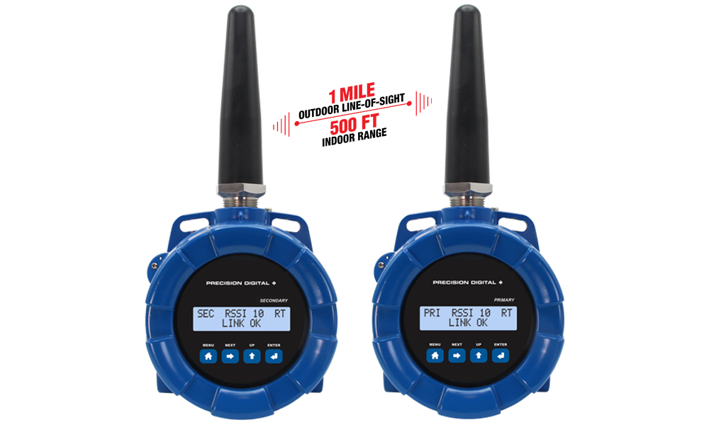
- Signal Wire Replacement Bridge Consisting of a Matched Pair of Wireless Field Units
- Virtually Plug and Play Right out of Box
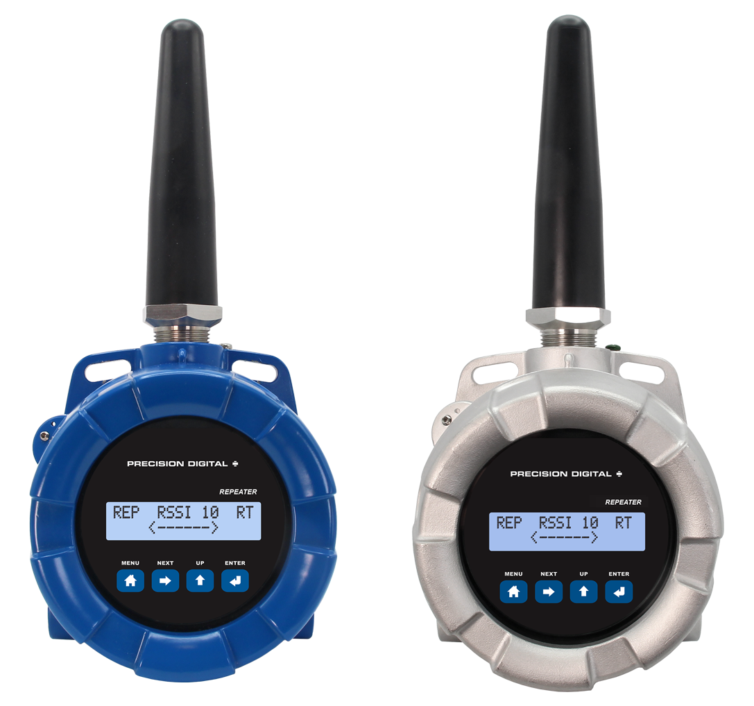
- Range: 1 Mile Line-of-Sight Outdoor, 500 Feet Indoor; Repeaters Available to Extend Range
- Wireless Transmission Between Primary and Secondary Unit of
- ◦ 4-20 mA (Separate Signals Going Both Ways)
- ◦ Discrete (4 digital I/O Signals Going Both Ways)
- ◦ RS-485 Modbus
- Inputs: (Wired to Units) 4-20 mA or 0-10 V (1), Discrete/Digital (up to 4), Modbus
- Outputs: (Wired to Units) 4-20 mA (1), Discrete/Digital (up to 4), Relays (2, optional), Modbus
- Loss of Signal (LoS) Digital Output
- PDA10 Signal Strength Survey Tool to "Try Before You Buy"
- Field Installable Relay Module with Two Form A (SPST) 5A Relays (Available for Both Units)
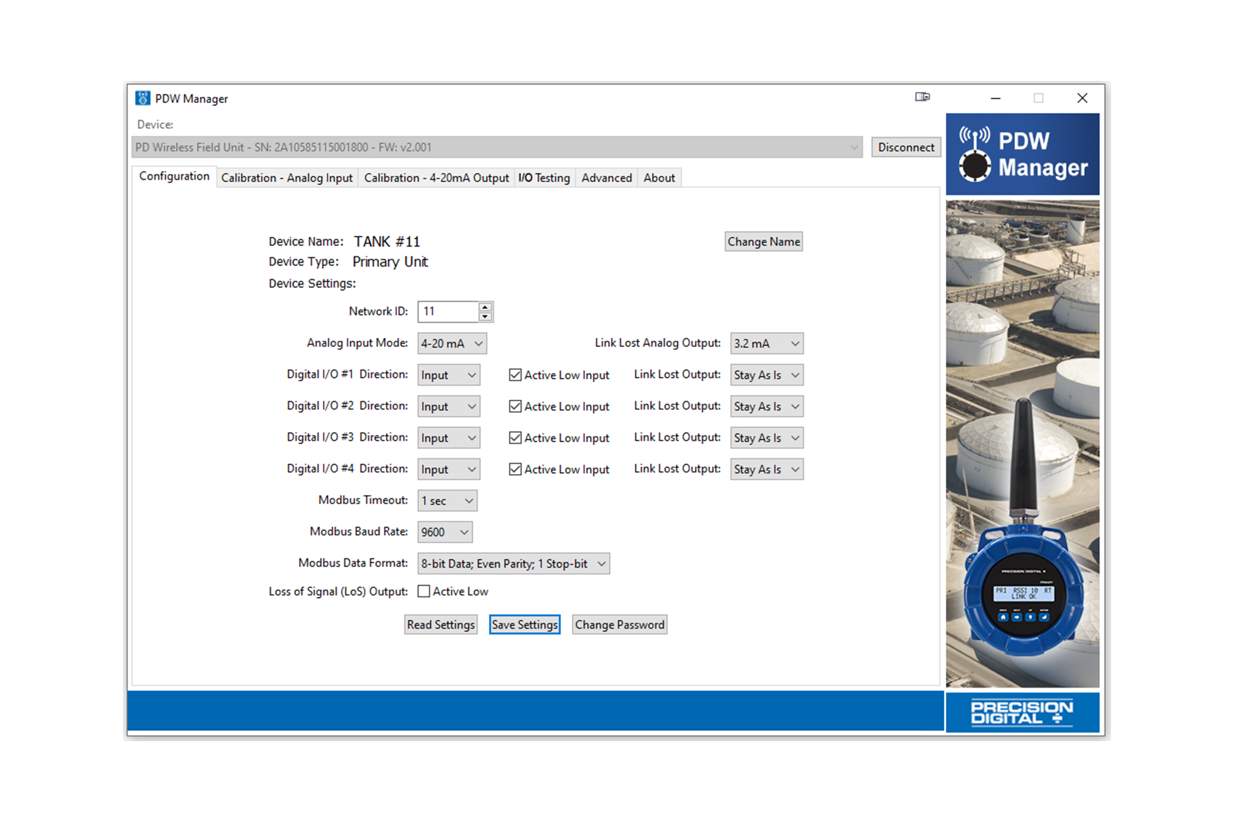
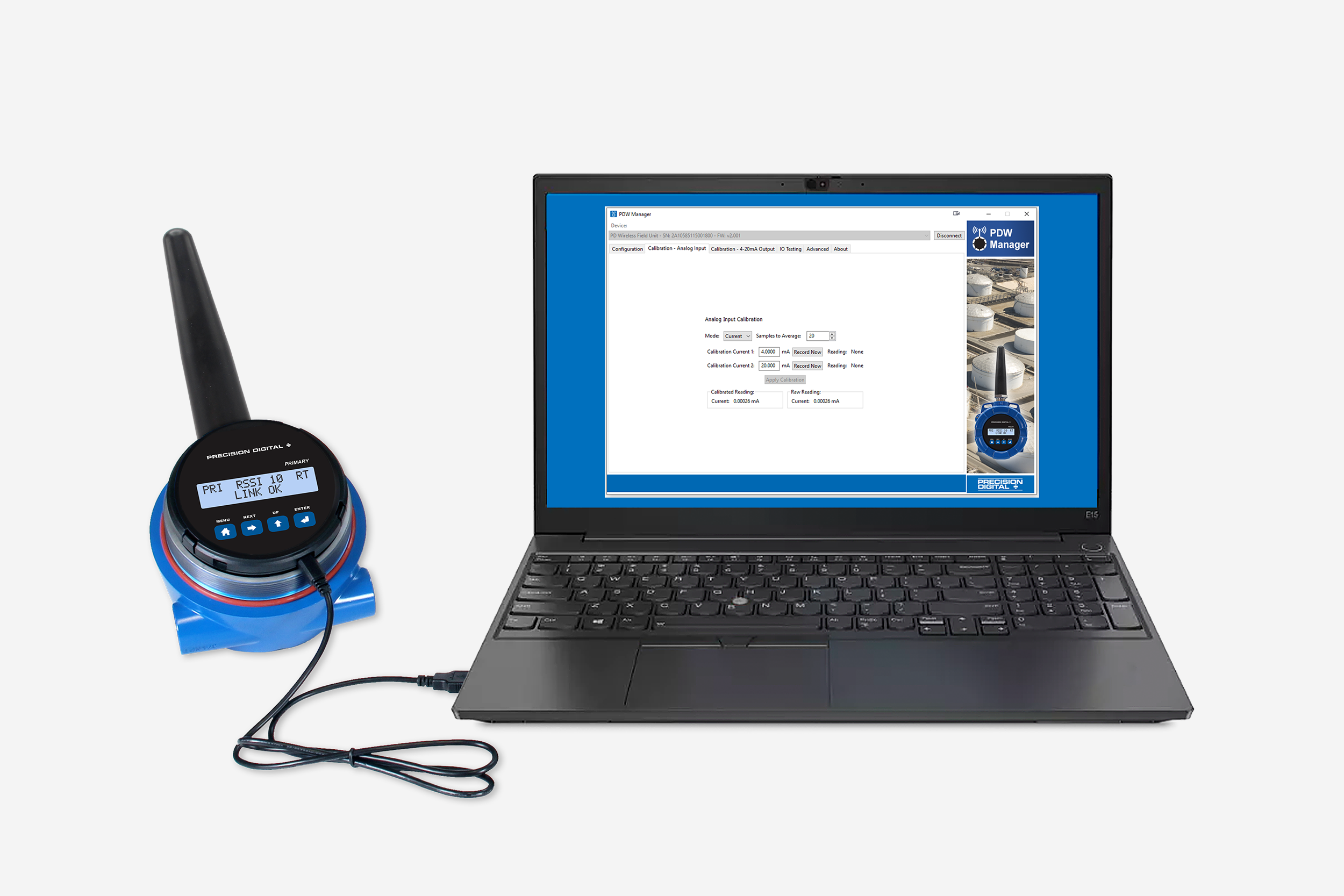
- Simple to Configure Using PDW Manager Programming Software and On-Board USB
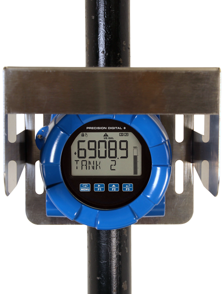
- Backlit Display Provides Helpful Input & Output Information
- CapTouch Through-Glass Button Programming for Non-Advanced Settings
- Device Communication Secured by Enabling 128-bit AES Encryption
- Password Protection
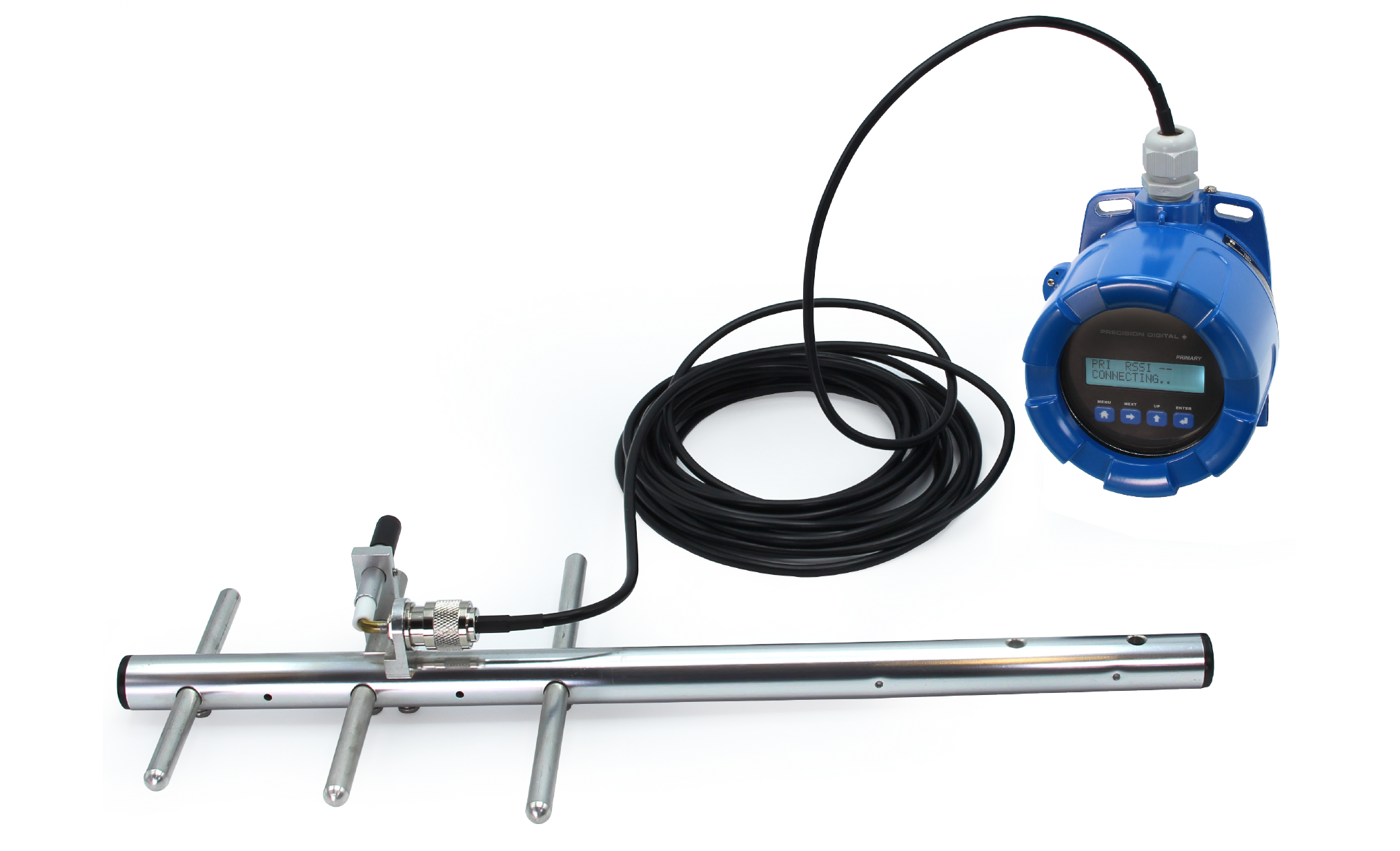
- Remote Yagi Directional Antennas Available
- IP68, NEMA 4X Aluminum & Stainless Steel Enclosures With Plenty of Room for Field Wiring
- Operating Temperature Range: -55 to 75°C (-67 to 167°F)
- Conformal Coated PCBs for Dust & Humidity Protection
- Flange for Wall or Pipe Mounting; Loop for Stainless Steel Tag; Holes for Tamper-Proof Seal
- Conformal Coated PCBs for Dust & Humidity Protection
- 9-30 VDC Power
- 3-Year Warranty
** NEW IMPROVED WEB STORE! | All users must register for a new account. | Register now > **
BUY ONLINE TO SAVE TIME AND INCREASE ORDER ACCURACY!

Questions? (508) 655-7300
Point-To-Point Wireless Bridge
PDW30 Aluminum Front


Models in stock
from $875.00
The PDW30 Point-to-Point Wireless Bridge is a plug-and-play signal wire replacement system consisting of a matched pair of wireless field units that transmit 4-20 mA, discrete, and Modbus signals between two points without running signal wiring. With bidirectional communication, up to 1 mile outdoor line-of-sight range, optional relay outputs, and simple setup using PDW Manager software and on-board USB, the PDW30 is ideal for industrial monitoring and control applications where wiring is impractical or costly.
Why Should You Buy:
- Replaces signal wiring between two points
- Sends 4-20 mA, digital, and Modbus signals wirelessly
- Simple setup with USB and PDW Manager software
- Up to 1 mile line-of-sight range