OPERATION
The PDA1500 High Voltage AC/DC to Logic Level Converter accepts up to four high voltage input signals and outputs a TTL logic (5 V) signal representative of each input's status, whether high voltage is present or not.
Normal Mode
In Normal Mode operation, the converter detects the presence of high voltage on input channels CH1 to CH4. If high voltage is present, the corresponding output 1-4 will be high, as seen in Figure 4. If voltage is below the detection range, the corresponding output will be low.
Normal Mode for AC Limiter Switches
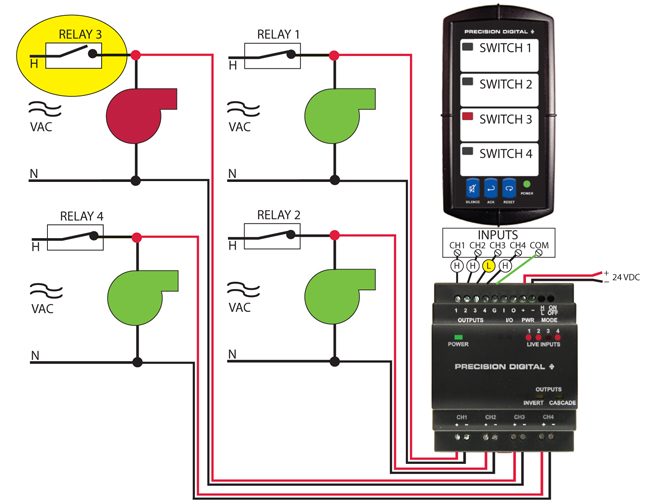
Figure 4: Normal Mode Example
Normal Mode may be used to set alarm conditions on a Vigilante II annunciator when high voltage is not present on an input channel, such as when an interlock relay has opened. In this example, since limit switch 3 (relay 3) is open, high voltage is not present at input channel 3 (CH3). The resulting low output from output 3 triggers the Vigilante II annunciator to alarm the corresponding input, as well as sound the 85dB alarm in order to alert the operator of the alarm condition. This setup can be used to alarm based on safety interlocks, fuse failures, or any other condition that would break the high voltage line. In this mode, the converter's output condition matches the input condition.
Inverted Mode
In Inverted Mode operation, the state of all outputs is the inverse of what they would be in Normal Mode. The converter detects the presence of high voltage on input channels CH1 to CH4. If high voltage is present on an input channel, the corresponding output 1 to 4 will be low, as seen in Figure 5. If voltage is below the detection range on an input channel, the corresponding output will be high.
Inverted Mode for Pumps
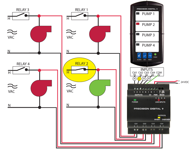
Figure 5: Inverted Mode Example
Inverted Mode may be used to set alarm conditions on a Vigilante II annunciator when high voltage is present on an input channel, such as when a relay closure supplied power to a pump. In this example, relay 2 has closed, applying power to pump 2. Input channel 2 (CH2) will detect high voltage. Because the converter is in Inverted Mode, the output is in the "Low" state, the opposite state of the input. Output channel 2 is subsequently Low. The Vigilante II is configured to light an LED on an input Low signal, and therefore the annunciator shows that pump 2 is active. The Vigilante II is configured to sound an 85 dB audible alarm while the alarm condition is present, and automatically clear when the alarm condition clears. In this mode, the converter's output condition is the opposite of the input condition.
Cascade Mode
Cascade Mode is a special operation mode used for the monitoring of high voltage interlocks where one failure causes a failure of all monitoring points further down in the system. Examples of this include the many interlocks on boiler systems, where a single failure can cause a cascade of failures later in the system. Cascade Mode will indicate the single point of failure in these series systems, as seen in Figure 6.
Cascade mode provides a digital output alarm state if the corresponding input channel is active, but the next subsequent input channel is inactive. This can be used to identify the single point of system failure, without indicating every alarm state throughout the linked series interlock system. Cascade mode utilizes exclusive NOR (inverting OR) logic.
Cascade Mode for Boiler System Control
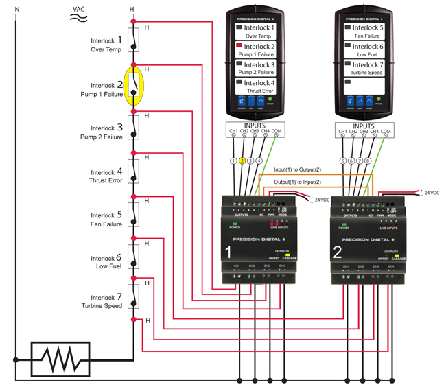
Figure 6: Cascade Mode Example
Cascade Mode may be used to set alarm conditions for multiple relays or interlocks wired together in a series. In this configuration, the first interlock in a system to encounter a problem opens the high voltage circuit, and is the only alarm output triggered by the PDA1500. In this example, since the signal output for Interlock 2 is now cut, the interlock triggers the Vigilante II annunciator to turn off the entire system, and sound the 85dB alarm in order to alert the operator of the alarm condition. The LED indicating the point of failure on the Vigilante II Annunciator can remain lit until reset. In this case, the point of failure is pump-related at Interlock 2, so investigation into the problem can begin there. The corresponding LED on the PDA1500 is independent of the Vigilante II; LEDs on the PDA1500 (Live Inputs) are always ON when high voltage is present and always OFF when high voltage is not present. Notice how PDA1500 #1's output (O) is wired to PDA1500 #2's input (I) and vice versa. This allows the two PDA1500 units to properly monitor the inputs for Cascade Mode.
Inverted Cascade Mode
Inverted Mode may be applied to Cascade Mode. When the H/L pushbutton is latched in the recessed position, Inverted Mode is active. The outputs behave using the same logic as in Cascade Mode, but the output states are all inverted. This makes the Cascade Mode output function using exclusive OR (XOR) logic. Inverted Cascade Mode will also work across multiple units.
Multiple Unit Cascade Mode
Cascade Mode logic may be combined across multiple Logic Level Converters to monitor more than 3 alarm outputs (or 4 inputs). When wired together, output four (4) of a Logic Level Converter will monitor input CH4 and CH1 of the next Logic Level Converter wired in series with it. Multiple unit Cascade Mode may be used across an unlimited number of units. See Figure 6.
DIMENSIONS
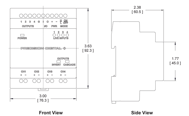
Figure 7: Dimension Drawings


