Includes a convenient storage case

Features

  • Measure and Source T/Cs, RTDs, Ohms, Current, Voltage
  • Compact & Lightweight
  • Battery or USB Powered
  • Descriptive LCD Display
  • 24 V Power to Drive the Transmitter
  • Auto Stepping & Auto Ramping
  • Selective Auto Off Mode
  • LCD includes an LED backlight

Overview

This 
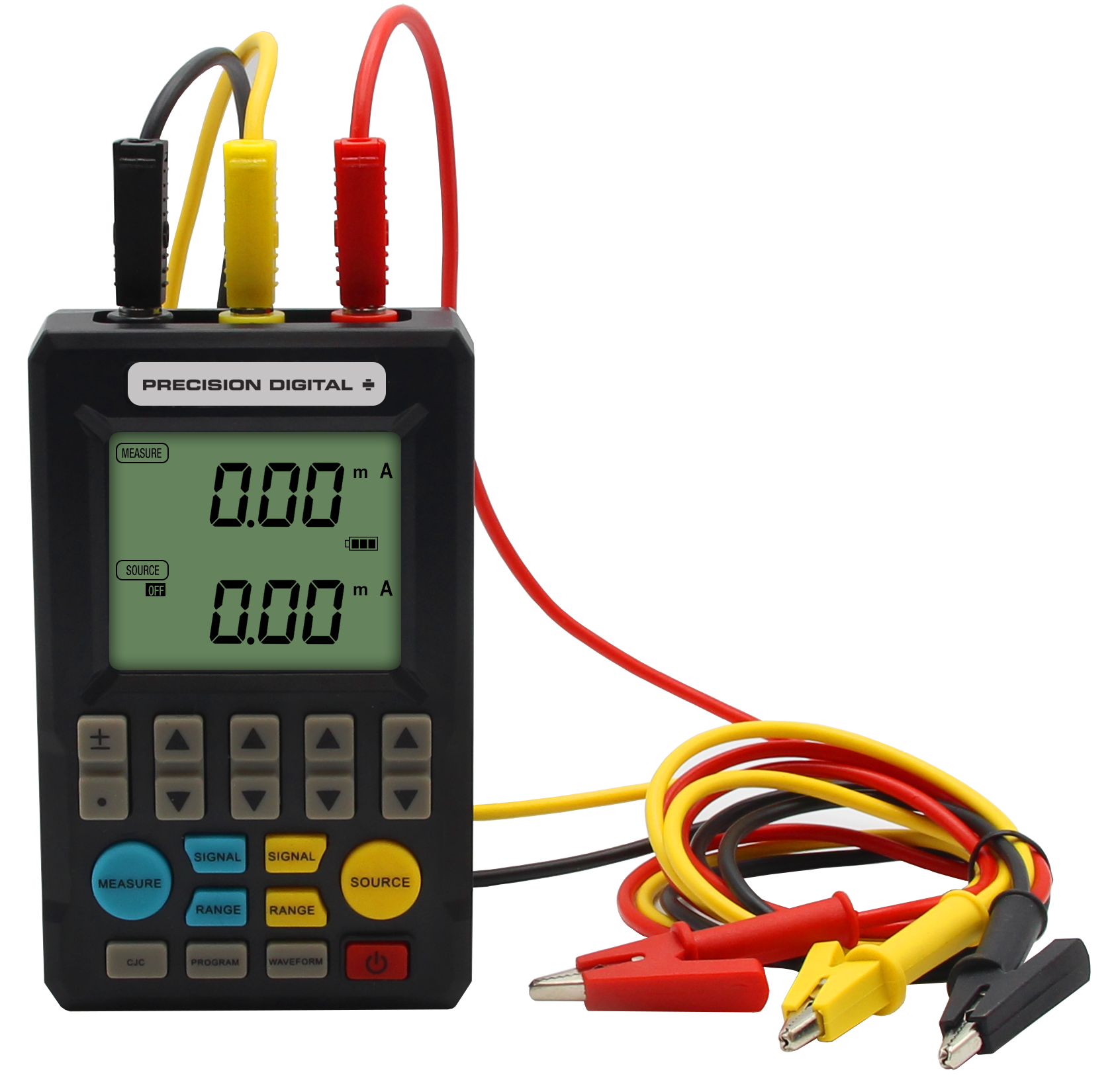
PD9501 Multi-Function Calibrator has a variety of signal measurement and output functions, including voltage, current, thermocouple, and RTD.

Main Function

Voltage Signal: 0-30 V, 0-25 mV, 0-100 mV output and measurement.
Current Signal: Active and passive 0-25 mA, 4-20 mA output and measurement.
Thermocouple: K, E, J, T, R, B, S, N output and measurement. Note: Output Range Starts from 0°C
RTD: PT100 output and measurement.
Ohms: Output and measurement

The PD9501 includes a convenient storage case.

The PD9501 includes a convenient storage case.

Functions

PD9501 Functions

Terminal Blocks

① Common (Black)
② Output Terminal (Yellow)
③ Measurement Terminals (Red)

Buttons

④ Numeric Modifier Keys

Increase or decrease values Increase or decrease values

Toggle numeric decimal points Toggle numeric decimal points

Toggle value plus or minus Toggle value plus or minus

⑤ Measurement Function Keys (Blue)
     [Signal]: toggle signal type
     [Range]: toggle measurement range
     [Measure]: open/exit measurement function

⑥ Cold Junction and Programming Function Keys
     [CJC]: display/modify cold end
     [Program]: turn on the programming function
     [Waveform]: change programmable output waveform

[Power]: turn power on/off

⑧ Output Function Keys (Yellow)
     [Signal]: toggle output signal type
     [Range]: toggle output range
     [Source]: open/turn off signal output

⑨ Dip Switch (Factory defaults to OFF-Down)
  1. Auto Power Off: 10 minutes without key operation, automatic shutdown.
  2. Manual Cold End: Manually set the cold end value when measuring thermocouples.
  3. Passive Output: outputs a passive current signal for analog transmitters.
  4. Low Load Mode: When the passive current is input, calibrator supplies 16 V to the transmitter to reduce power consumption and prolong the use time.

LCD Display

     a: Measurement: 4 digits with unit
     b: Output signal value: 4 digits with unit
     c: Signal and cold end mode: 20 mV, 100 mV, 4-20 mA, K, E, J, T, R, B, S, N
          RJA: automatic cold junction compensation
          M: manual set cold junction compensation
     d: Programming function: n/m to split the output, Output value = (Main Set Value)*(n/m)
          Sweep: Linear output, Linear output signal
          Step: Stepping output
          Time: Output time for each step, 0-999s can be set.
          Count: Output cycles, 0-999 times can be set, 0 is infinite
     e: Unit: mA/mV/°C
     f: Range and change function:
          RL: Show the lower range limit
          RH: Show the high range limit
          SL: Show the minimum signal
          SH: Show the maximum signal
     g: Battery: Indicates battery life

Signal Output

The calibrator can output voltage, active current, passive current, thermocouple, and RTD signals.

Voltage, Active Current Output

① Connect the black wire to the common terminal, connect the yellow wire to the output terminal
② Press [Signal] to toggle the signal type
③ Press Increase or decrease values to adjust the output value
④ Press [Source], the "source" will change from OFF to ON and start the output function

4-20 mA Output

① Choose 4-20 mA for signal type
② Press the opposite [Signal]. You can choose 4→8→12→16→20 or press Increase or decrease values to adjust
③ Press [Source] to open the output function

Figure 1: Output Active Current/Voltage to the meter or PLC

Figure 1: Output Active Current/Voltage to the meter or PLC

RTD and Thermocouple Output

Note: On thermocouple, the output temperature is minus the voltage value corresponding to the cold junction temperature.

① Press [Signal] to select signal type. Choose from K, E, J, T, R, B, S, N, RTD, Ω
② Press Increase or decrease values to set output value of temperature
③ Press [Source] to open the function

Passive Current Output

Active with DIP Switch setting

Passive current output can be used as a 2-wire transmitter simulator for loop testing.

① Choose 4-20 mA for signal type
② Press the opposite [Signal]. You can choose 4→8→12→16→20 or press the Increase or decrease values to adjust
③ Press [Source] to open the output function

Figure 2: 2-wire Transmitter Simulator

Figure 2: 2-wire Transmitter Simulator

Voltage, Current Signal Output or Measurement by Display Range (Eliminates range conversions)

① Signal type must be voltage or current
② Press [Range] to select display range limit: RL, RH, S1L, SH2
③ When “RL” is selected press Increase or decrease values to set value
④ Setup the RL, RH, SL, SH in turn


OUTPUT
⑤ Press [Range] to exit the rage setup.
     Press Toggle numeric decimal points to toggle between signal output or range output (no units are displayed on output)
⑥ Press the Increase or decrease values to change the output value
⑦ Press [Range] to open the function

MEASURE
⑤ Press [Range] to exit the rage setup.
     Press Toggle numeric decimal points to toggle between signal value or range output (no units are displayed on output)
⑥ It shows the measurement or conversion value according to range

Signal Measurement

The calibrator can measure voltage, active current, passive current, thermocouple signal, and RTD.

When measure function is not in use press [Measure] to turn off the measure mode to conserve battery power.

Voltage, Active Current Measurement

① Connect the black wire to the common terminal, connect the red wire to the measure terminal
② Press [Measure] to open measure function
③ Press [Signal] to toggle signal type
④ Shows value in the LCD screen

Figure 3: Measurement voltage, active current

Figure 3: Measurement voltage, active current

Passive Current Measurement

① Wiring as the 2-wire or 3-wire system
② Press blue [Signal] to set signal type to 24 V loop
③ Generator outputs 24 V (or 16 V when via DIP switch to low power mode)
④ Shows value in the LCD screen

Figure 4: Measure 2-wire transmitter

Figure 4: Measure 2-wire transmitter


Figure 5: Measure 3-wire transmitter

Figure 5: Measure 3-wire transmitter

RTD and Thermocouple Measurement

① Connect the black wire to the common terminal, connect the red wire to the measuring terminal
② Press blue [Measure] to set signal type to K, E, J, T, R, B, S, N, RTD, Ω
③ Value is displayed on the LCD screen

To view or adjust cold junction temperature for thermocouple:

① Press [CJC] to display cold end temperature
② If the LCD displays “RJA” the cold end is collected by the internal sensor and cannot be modified.
③ Select the “M” on the LCD to manually set the cold end value.

Programmable Output

Scaled Output Function (n/m)

The voltage, current, and thermocouple signals can be scaled by n/m.

Output value = (Main Set Value) × (n/m)

① Press Increase or decrease values to change the main setpoint
② Press [Program] to open split output mode to display n/m menu
③ Set (m) from 1 to 20
④ Set (n) from 0 to 20
⑤ Press yellow [Source] to open/exit the output
⑥ Press [Program] to exit the split output function

Linear Output Function

The signal value can be output linearly according to the time set by the user.

① Press Increase or decrease values to set value for the main set point
② Press [Waveform] to display “sweep”. This enables linear output function.
③ Press [Program] to set output time for rise time, hold time [top], fall time, hold time [low].
     Press Increase or decrease values to set time between 0-999s.
④ Press [Program] again to set number of linear outputs from 0-999.
⑤ Press yellow [Source] to open/exit the output
⑥ Press [Program] to exit the linear output function

Linear output functions

Automatic Step Output Function

The signal value can be stepped out according to the user-defined value.

① Press Increase or decrease values to set value for the main setpoint
② Press [Waveform] to display “step”. This enables step output function.
③ Press [Program] to set “time”. Press Increase or decrease values to set time between 0-999s.
④ Press [Program] again to set N/m for step output
⑤ Press yellow [Source] to open/exit the output
⑥ Press [Program] to exit the step output function

Step out wave

Specifications

Operating Temperature: 15 to 130°F (-10 to 55°C)
Storage Temperature: 5 to 158°F (-20 to 70°C)
Relative Humidity: 20 to 80%
External Dimensions: 4.5" x 2.8" x 1.1"
(114 mm x 71 mm x 28 mm) (H x W x D)
Weight: 11.0 oz (312 g), With batteries: 14.0 oz (397 g)
Power: Four AAA batteries or external USB power
Power Dissipation: 300 mA, 7-10 hours
Reverse Connection and Overcurrent Protection: 30 V
Cables Provided: Three signal cables

Accuracy Specifications

INPUTSIGNALRANGEACCURACYRESOLUTIONNOTE
DC Voltage20mV0.00-24.00 mV±0.2%0.01 mV
100 mV0.0-100.0 mV±0.2%0.1 mV
VOutput:
0.00-15.00 V
±0.2%0.01 VOutput:
Maximum current 30 mA
Measurement:
Input Impedance 1.2 M Ω
Measure:
±0.2% 0.01 V 0.00-30.00 V
±0.2%0.01 V
DC CurrentmA0.00-24.00 mA±0.2%0.01 VOutput:
Maximum load 750 Ω
Measurement:
Input Impedance 100 Ω
4-20 mA4/8/12/16/20 mA±0.2%0.01 mA
Passive CurrentmA0.00-24.00 mA±0.2%0.1 VOutput: External power 16-30 V
Power Output24 V LOOP24V/16 V±10%Drive Current:
24 mA
ThermocoupleK-270 to 1372°C±1%1°CThe output or measurement can not be less than the Cold Junction Temperature.

Output:
Range Starts from 0°C
E-270 to 1000°C±1%1°C
J-210 to 1200°C±1%1°C
T-270 to 400°C±1%1°C
R-50 to 1768°C±1%1°C
B0 to 1820°C±1%1°C
S-50 to 1768°C±1%1°C
N-270 to 1300°C±1%1°C
OhmsΩOutput:
15.0-400.0
Measure:
0.0-400.0
±0.2%0.1 ΩExcitation Current:
Min of 0.5 mA, Max of 3 mA
RTDPT100-199.0 to 650.0°C±0.2%0.1°C
loader.gif

Choose Your Options

Configurations other than those specified above are available at a $250 adder. Consult factory for desired model number and price.