- Fully Approved Explosion-Proof Modbus Scanners
- Modbus RS-485 RTU Scanner as Master, Slave, or Snooper
- Dual Analog Inputs (0-20 mA, 4-20 mA, 0-5 V, 1-5 V, and ±10 V)
- On-Board USB & RS-485 Serial Communication Standard
- Decimal or Feet & Inches (with Eighths & Sixteenths) Display Options
- Poll and Display up to 16 Process Variables
- Add, Diff, Avg, Multi, Div, Min, Max, Weighted Avg, Ratio, Concentration, & More
- Dual-Line 6-Digit Display, 0.6" (15 mm) & 0.46" (12 mm)
- SafeTouch Through-Glass Button Programming
- Display Mountable at 0°, 90°, 180°, & 270°
- 4 Relays with Interlocking Capability + Isolated 4-20 mA Output Option
- Password Protection
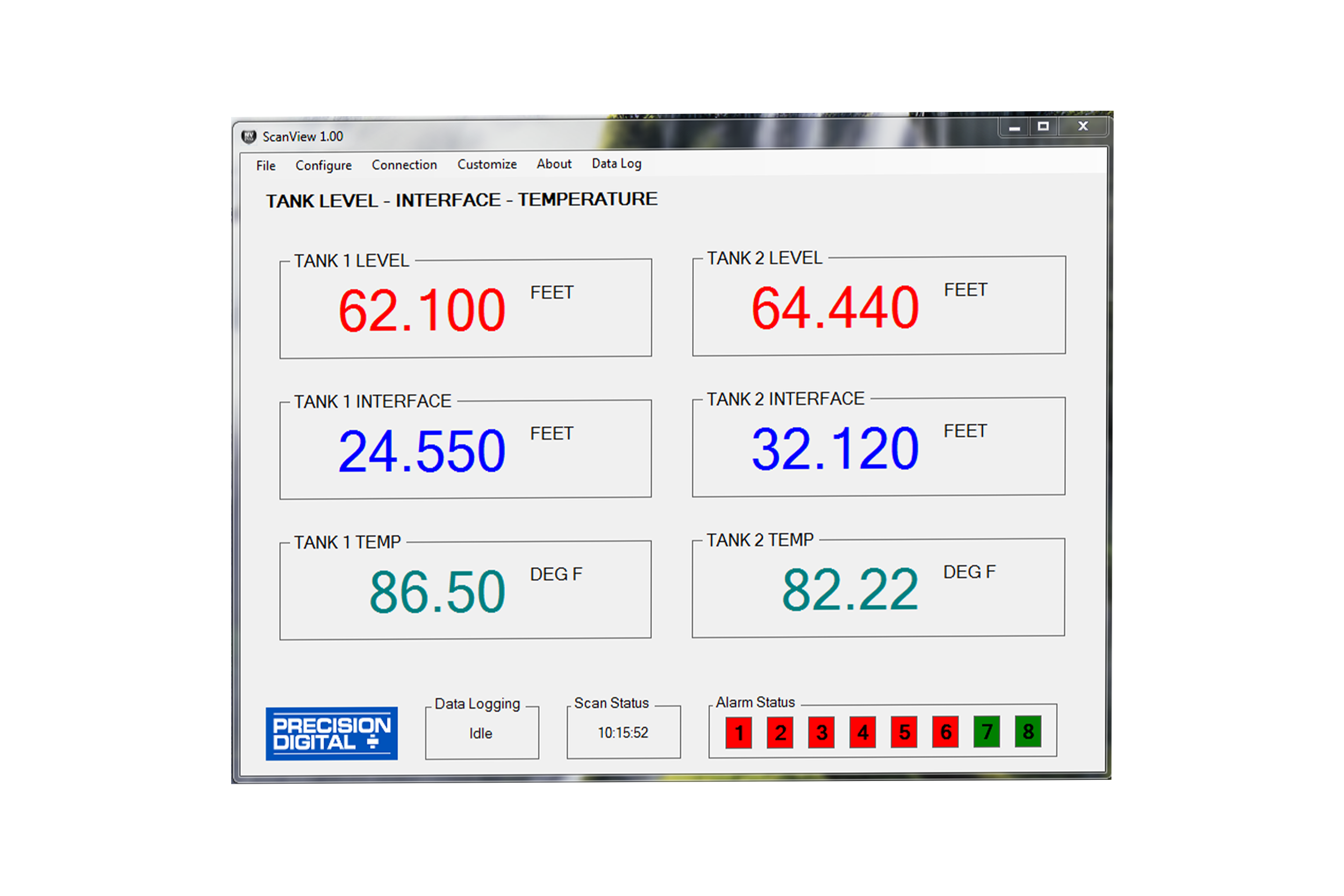
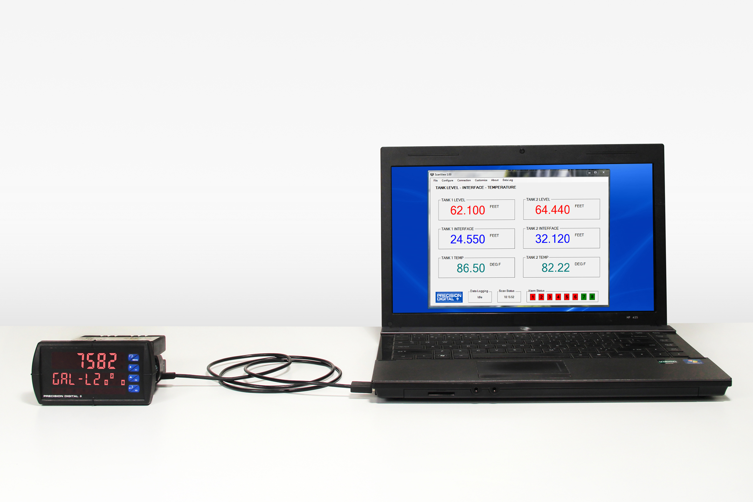
- Free PC-Based, On-Board, ScanView USB Programming Software
- SunBright Display Standard Feature; Great for Outdoor Applications
- Operating Temperature Range: -55 to 65°C (-67 to 149°F)
- CSA Certified as Explosion-Proof / Dust-Ignition-Proof / Flame-Proof
- ATEX and IECEx Certified as Flame-Proof
- Input Power Options: 85-265 VAC / 90-265 VDC or 12-24 VDC / 12-24 VAC
- Multi-Pump Alternation Control
- 32-Point, Square Root, or Exponential Linearization
- Flanges for Wall or Pipe Mounting
- Explosion-Proof Aluminum or Stainless Steel NEMA 4X / IP68 Enclosures
- Four 3/4" NPT Threaded Conduit Openings
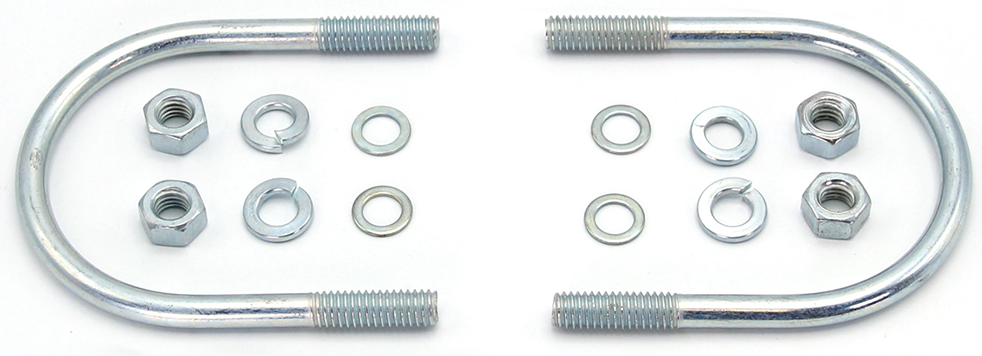
- Pipe Mounting Kits
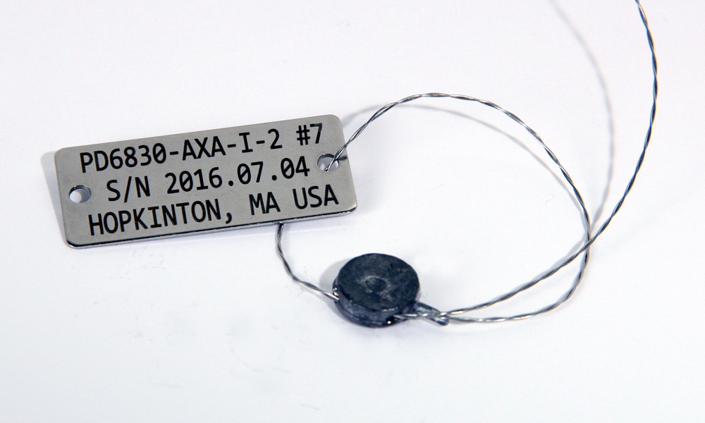
- Stainless Steel Tag Available
- 3-Year Warranty
** NEW IMPROVED WEB STORE! | All users must register for a new account. | Register now > **
BUY ONLINE TO SAVE TIME AND INCREASE ORDER ACCURACY!

Questions? (508) 655-7300
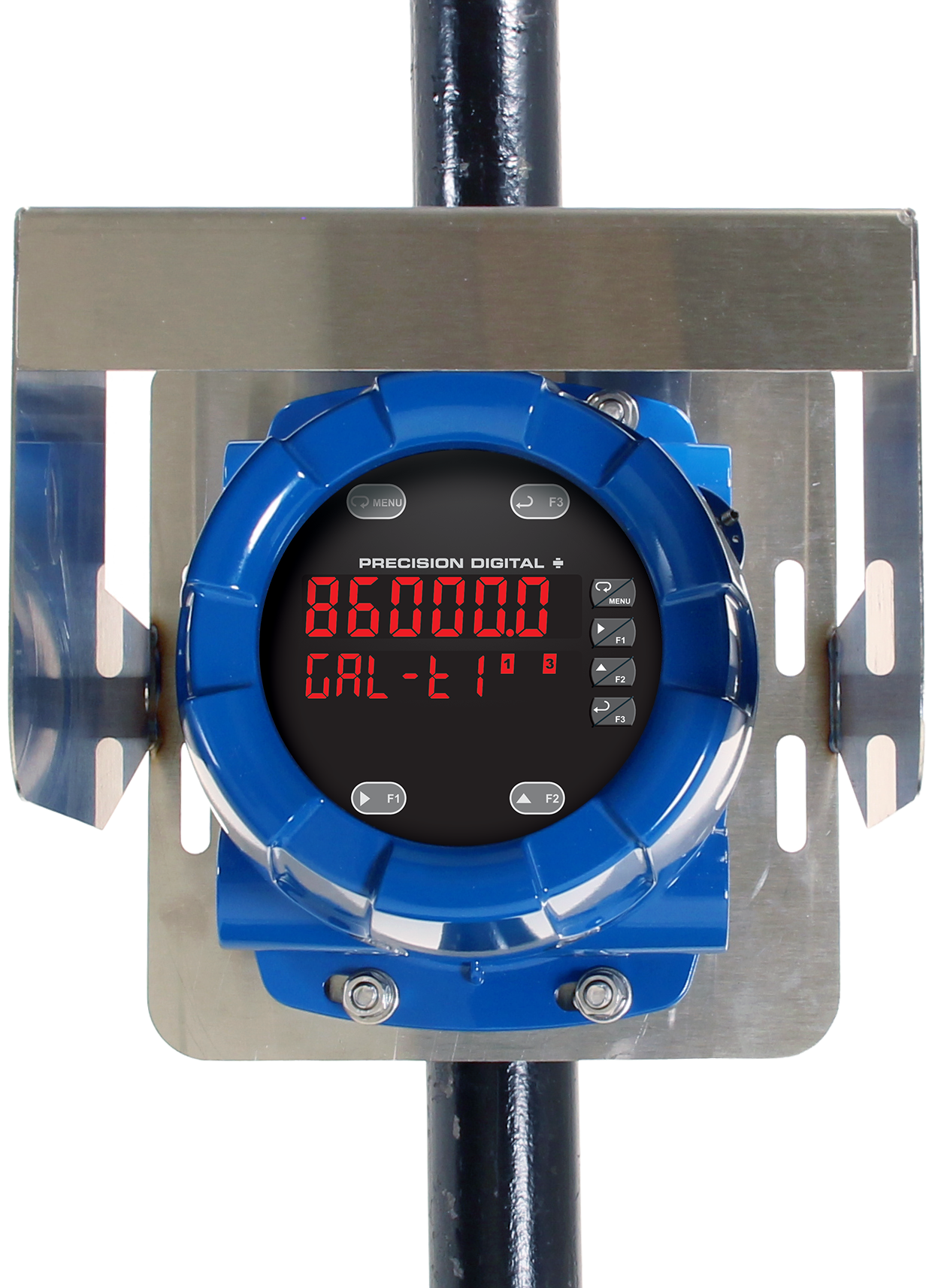
ProtEX-MAX Explosion-Proof Feet & Inches Modbus Scanner with Dual Analog Inputs
PD8-6081 in Aluminum Enclosure


Models in stock
from $1873.00
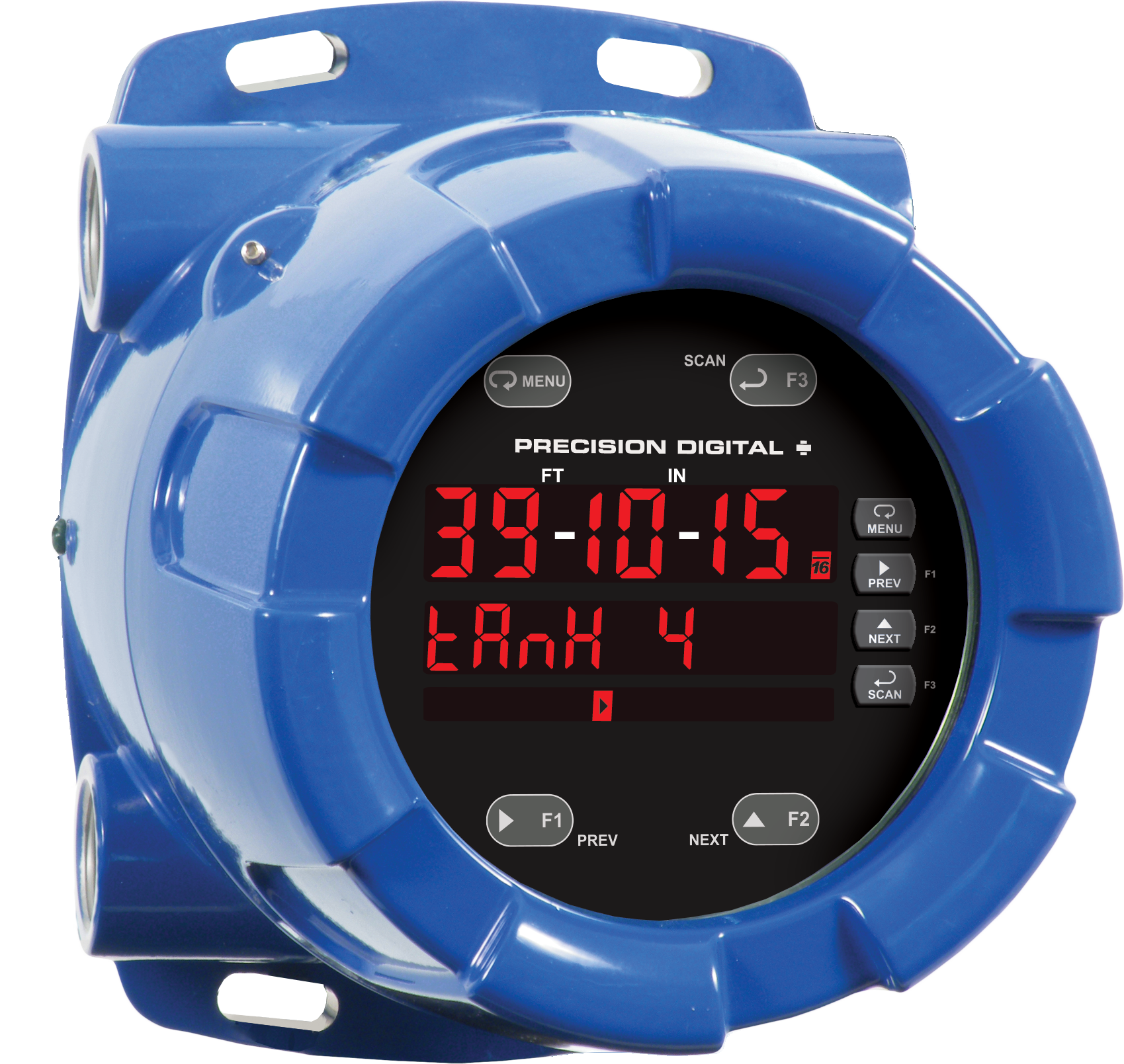
The ProtEX-MAX PD8-6081 Super Snooper feet & inches Modbus scanner offers all the functionality of the ProVu PD6081 as a CSA, ATEX, and IECEx certified explosion-proof product. It is available in an aluminum or stainless steel enclosure and will operate over a wide temperature range of -55 to 65°C (-67 to 149°F). It displays level information on a specially designed feet & inches display, instead of the usual decimal format. It is the ideal display for hazardous areas with Modbus level or multivariable transmitters and is capable of scanning up to 16 process variables. Its unique feet & inches upper LED display can indicate up to 99 feet, 11 and 15/16 inches. The 6-digit lower display can indicate units, tags, or other variables such as volume, temperature, or density. The PD8-6081 also has dual analog inputs, for integrating traditional 4-20 mA or voltage inputs in the display scanning. The scanner can be setup as a Modbus master, slave, or snooper. Various math functions may be applied to the analog or Modbus inputs, such as addition, difference, average, and ratio. The PD8-6081 can be equipped with four internal relays and a 4-20 mA output. It can be programmed and operated without opening the housing by using the built-in CapTouch through-glass buttons.
- Worldwide Explosion-Proof Approvals
- Feet & Inches Display
- Modbus Input
- Dual Analog Input