General
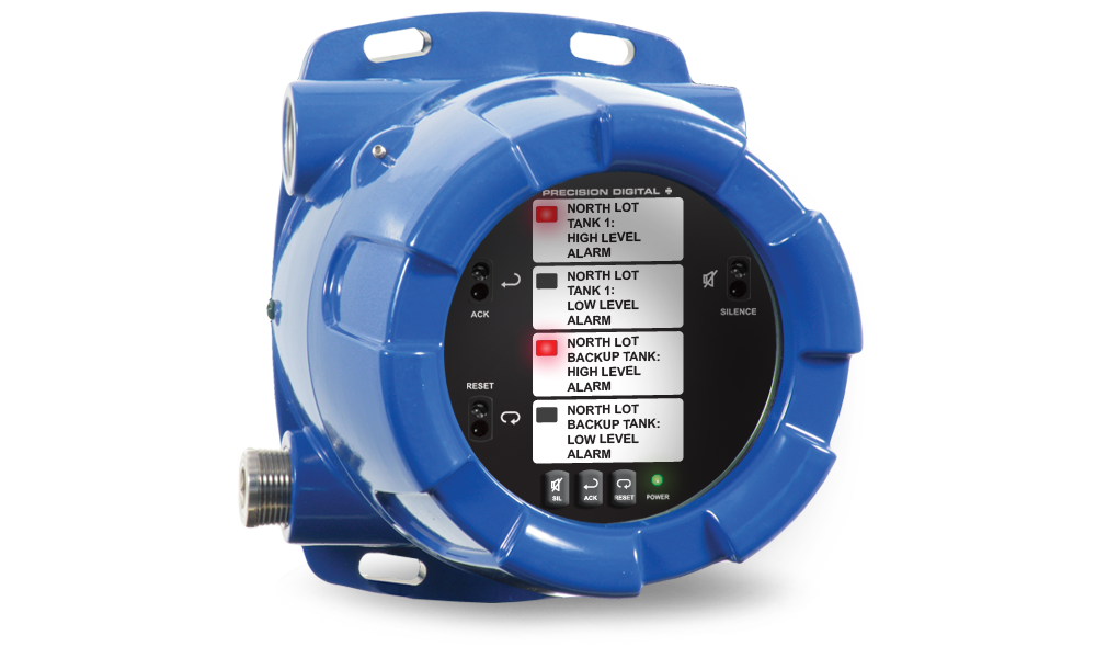
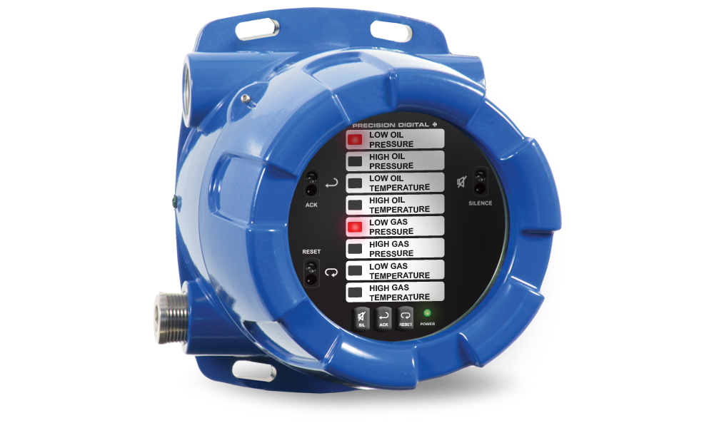
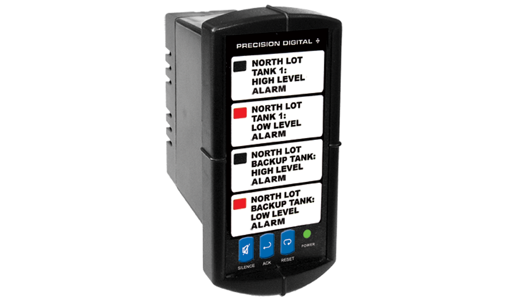
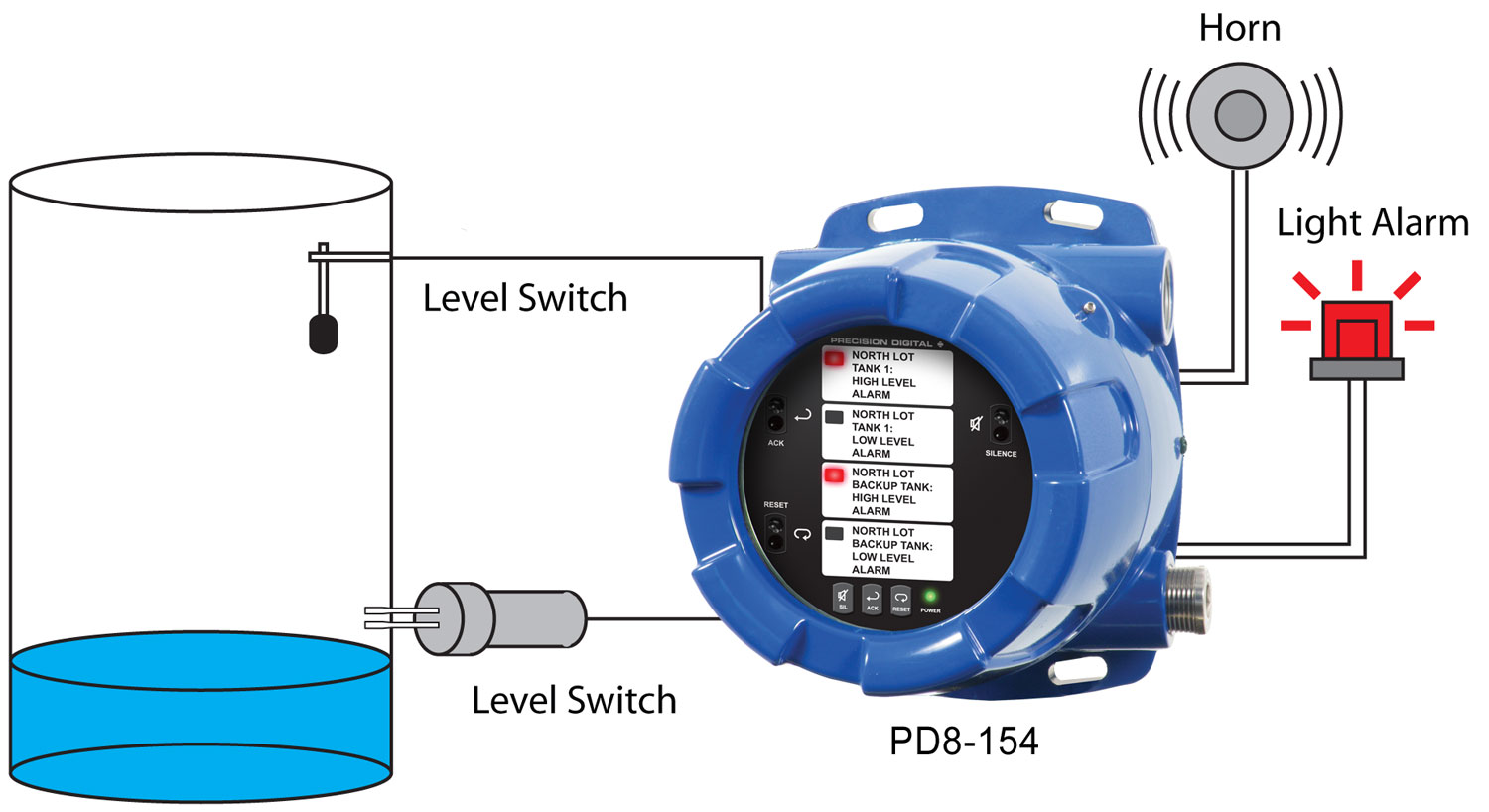
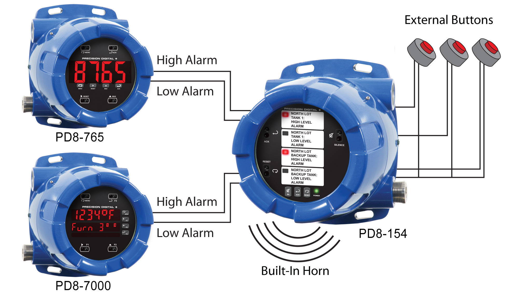
Display: PD8-154: Four red LED channel indicators. PD8-158: Eight red LED channel indicators. One green LED power indicator.
Alarm Messages: Custom printed adhesive clear labels.
Area: PD154, 1.25" x .60" (32 mm x 15 mm), 4 messages PD158, 1.25" x .25" (32 mm x 6 mm), 8 messages
User specified size and length, up to 4 lines (PD154) or 2 lines (PD158) of 14 characters of size 9 pt fonts.
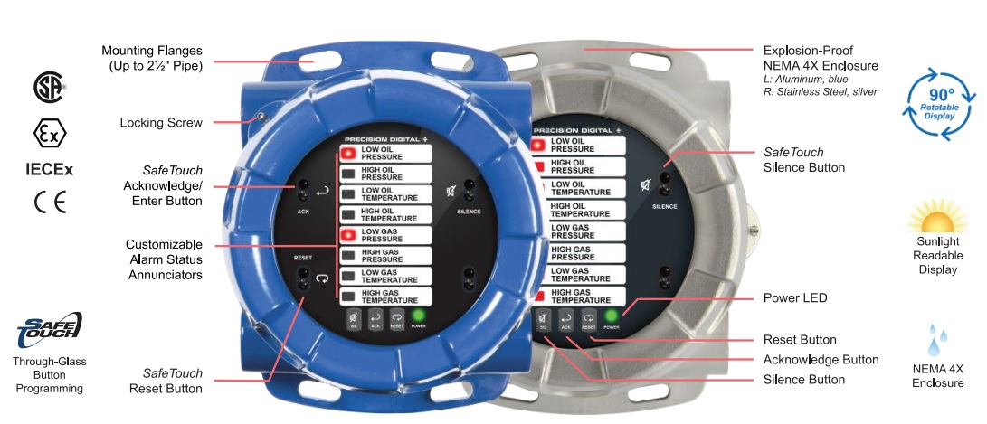
Programming Methods: Rear 4-position switch for sequence selection and horn operation. Three SafeTouch through-glass buttons for NO/NC input selection, sequence option, and operation when cover is installed. Three internal pushbuttons when cover is removed.
Audible Alarm: 85 dB internal horn. The use of an external explosion-proof horn is recommended due to the internal horn's audibility being dampened by the explosion-proof enclosure.
Noise Filter: 40 ms debounce on inputs and external push buttons.
Shared First-Out Systems: 1 ms unit-to-unit delay. Maximum of 200 units in the shared first-out system.
Non-Volatile Memory: All programmed settings are stored in non-volatile memory for a minimum of ten years if power is lost.
Power Options: 85-265 VAC, 50/60 Hz; 90-265 VDC, 20 W max; or 12-36 VDC, 12-24 VAC, 6 W max.
Fuse: Required external fuse: UL Recognized, 5 A max, slow blow. Up to 6 annunciators may share one 5 A fuse
Isolated Power Supply: 24 VDC ± 10% @ 200 mA max Standard on 85-265 VAC powered units only.
Isolation: 4 kV input/output-to-power line.
Overvoltage Category: Installation Overvoltage Category II: Local level with smaller transient overvoltages than Installation Overvoltage Category III.
Environmental: T6 Class operating temperature range: Ta = -40 to 60°C
T5 Class operating temperature range: Ta = -40 to 65°C
Storage temperature range: -55 to 85°C (-67 to 185°F)
Relative humidity: 0 to 90% non-condensing
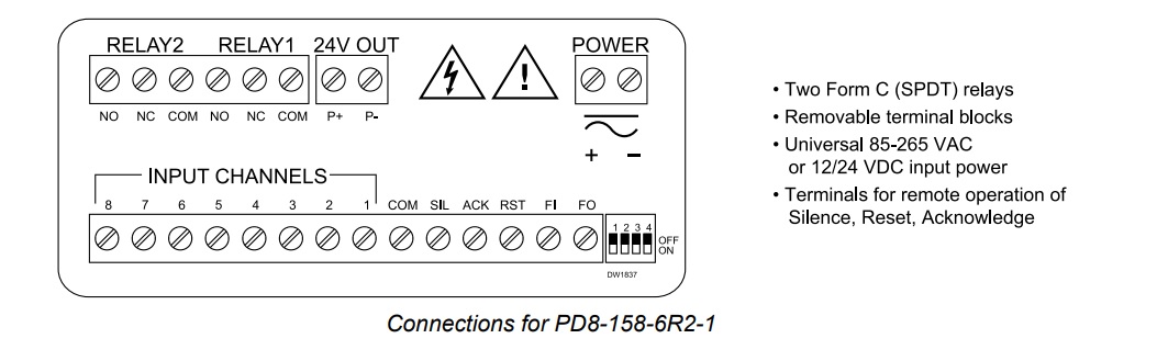
Connections: Removable screw terminal blocks accept 12 to 22 AWG wire.
Mounting: Four slotted flanges for wall mounting or NPS 1½" to 2½" or DN 40 to 65 mm pipe mounting.
Overall Dimensions: 6.42" x 7.97" x 8.47" (W x H x D) (163 mm x 202 mm x 215 mm)
Weight: Aluminum: 14.7 lbs (6.67 kg); Stainless Steel: 23.5 lbs (10.66 kg)
Warranty: 3 years parts & labor
Inputs
Input Types: NO or NC switches: No external excitation required.
Open collector transistor: Open circuit voltage approx. 3.3 VDC.
Logic Levels: LOW = 0 to 0.9 VDC, HIGH = 2.4 to 28 VDC
Update Rate: 41 ms following alarm state; 1 ms for alarm state clear.
Sequences: Input follower, ISA Sequences A, F1A, F2A, F3A, M, F1M, and F3M per ISA Standard ISA-18.1-1979 R2004.
Sequence Options: A, F1A, F2A, F3A, M, F1M, F2M, and input follower with selectable options -1 (silence push button), -4 (no lock-in), and -6 (no horn) per ISA Standard ISA-18.1-1979 R2004
Relays
Rating: 2 SPDT (Form C); rated 3 A @ 30 VDC or 3A @ 250 VAC resistive load; 1/14 HP @ 125/250 VAC for inductive loads.
Electrical Noise Suppression: A suppressor (snubber) should be connected to each relay contact switching inductive loads to prevent disruption to the microprocessor's operation. Recommended suppressor value: 0.01 µF/470 Ω, 250 VAC (PDX6901).
Relay Operation: Relay 1: Alarm state until alarm is acknowledged. Relay 2: Alarm state if any channel indicating alarm condition.
Fail-Safe Operation: Programmable independent for each relay.
Note: In fail-safe mode, relay coil is energized in non-alarm condition. In case of power failure, relay will go to alarm state.
Enclosure
| Material | -AL Models: ASTM A413 LM6 die-cast aluminum, copper-free, enamel coated
-SS Models: ASTM A743 CF8M investment-cast 316 stainless steel |
| Gasket | Fluoroelastomer |
| Rating | NEMA 4X, IP68 Explosion-proof |
| Color | -AL: Blue
-SS: Silver |
| Window | Borosilicate glass |
| Conduits | Four ¾" NPT threaded conduit openings |
| Conduit Stopping Plugs | Sold separately |
| Flanges | Two built-in flanges for wall and pipe mounting. |
| Tamper-Proof Seal | Cover may be secured with tamper-proof seal. |
| Overall Dimensions | 6.42" x 7.97" x 8.47" (W x H x D)
(163 mm x 202 mm x 215 mm) |
| Weight | AL: 14.7 lbs (6.67 kg)
SS: 23.5 lbs (10.66 kg) |
| ATEX | Flameproof
 II 2GD II 2GD
Ex db IIC Gb
Ex tb IIIC Db
IP66/IP68
Tamb: -55°C to +85°C
Certificate No.: Sira 19ATEX1252U |
| IECEx | Flameproof and dust protection
Ex db IIC Gb
Ex tb IIIC Db
IP66/IP68
Tamb: -55°C to +85°C
Certificate No.: IECEx SIR 19.0075U |
| CSA | Class I, Division 1, Groups A, B, C, D
Class II, Division 1, Group E, F, G
Class III
Ex db IIC Gb
Ex tb IIIC Db
Class I, Zone 1, AEx db IIC Gb
Zone 21, AEx tb IIIC Db
IP66/IP68/TYPE 4X
Tamb: -55°C to +85°C
Certificate No.: 80011200 |
| UL | Class I, Division 1, Groups A, B, C, D
Class II, Division 1, Groups E, F, G
Class III
Class I, Zone 1, AEx db IIC Gb
Zone 21, AEx tb IIIC
Ex db IIC Gb
Ex tb IIIC Db
IP66/IP68/TYPE 4X
Tamb: -55°C to +85°C
Certificate Number: E518920 |
| Note: The above approvals are for the enclosure only. See below for approvals on the entire instrument. |
General Compliance Information
Electromagnetic Compatibility
| Emissions | EN 55022
Class A ITE emissions requirements |
| Radiated Emissions | Class A |
| AC Mains Conducted Emissions | Class A |
| Immunity | EN 61326-1
Measurement, control, and laboratory equipment
EN 61000-6-2
EMC heavy industrial generic immunity standard |
| RFI - Amplitude Modulated | 80 -1000 MHz 10 V/m 80% AM (1 kHz)
1.4 - 2.0 GHz 3 V/m 80% AM (1 kHz)
2.0 - 2.7 GHz 1 V/m 80% AM (1 kHz) |
| Electrical Fast Transients | ±2kV AC mains, ±1kV other |
| Electrostatic Discharge | ±4kV contact, ±8kV air |
| RFI - Conducted | 10V, 0.15-80 MHz, 1kHz 80% AM |
| AC Surge | ±2kV Common, ±1kV Differential |
| Surge | 1KV (CM) |
| Power-Frequency Magnetic Field | 30 A/m 70%V for 0.5 period |
| Voltage Dips | 40%V for 5 & 50 periods
70%V for 25 periods |
| Voltage
Interruptions | <5%V for 250 periods |
| Note: Testing was conducted on meters with cable shields grounded
at the point of entry representing installations designed to optimize
EMC performance. |
Product Ratings and Approvals
| CSA | Class I, Division 1, Groups B, C, D
Class II, Division 1, Groups E, F, G
Class III, Division 1
Class I Zone 1 Ex db IIC
Zone 21 Ex tb IIIC T90°C
-55°C < Tamb. < +60° C; Temperature Code T6
-55°C < Tamb. < +65° C; Temperature Code T5
Enclosure Type 4X & IP66 / IP68
Certificate Number: 2531731 |
| ATEX | II 2 G D
Ex db IIC T* Gb
Ex tb IIIC T90°C Db IP68
Ta = -55°C to +*°C
*T6 = -55°C to +60°C
*T5 = -55°C to +65°C
Certificate Number: Sira 12ATEX1182X
|
| IECEx | Ex db IIC T* Gb
Ex tb IIIC T90°C Db IP68
Ta = -55°C to +*°C
*T6 = -55°C to +60°C
*T5 = -55°C to +65°C
*T5 = -55°C to +65°C
Certificate Number: IECEx SIR 12.0073X
|
ATEX/IECEx Specific Conditions of Use:- The equipment label and epoxy coating may
generate an ignition-capable level of electrostatic
charges under certain extreme conditions. The
user should ensure that the equipment is not
installed in a location where it may be subjected
to external conditions (such as high-pressure
steam) which might cause a build-up of
electrostatic charges on non-conducting
surfaces. Additionally, cleaning of the equipment
should be done only with a damp cloth.
- Flameproof joints are not intended to be repaired.
- All entry closure devices shall be suitably certified
as “Ex d”, “Ex t” and “IP66/68” as applicable.
Suitable thread sealing compound (non-setting,
non-insulating, non-corrosive, not solvent based,
suitable for the ambient rating) must be used at
the NPT conduit entries to achieve the IPx8
rating while maintaining the Ex protection
concept.
Year of ConstructionThis information is contained within the serial number
with the first four digits representing the year and
month in the YYMM format.
For European Community:The ProtEX-MAX must
be installed in accordance with the ATEX directive
2014/34/EU, and the product certificate Sira
12ATEX1182X.