General
Input: 0-300 VDC
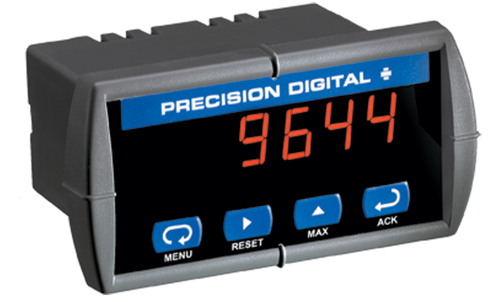
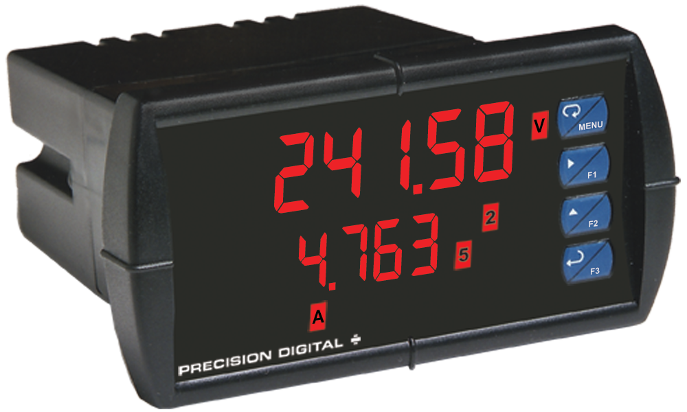
Display: 0.56" (14.2 mm) red LED, 4 digits (-1999 to 9999)
Accuracy: ±0.05% FS ±1 count
Display Intensity: Eight user selectable intensity levels
Decimal Point: Up to 3 decimals: d.ddd, dd.dd, ddd.d, or dddd
Front Panel: NEMA 4X, IP65; panel gasket provided
Programming Methods: Four front panel buttons, cloning with Copy feature, and Modbus registers
Noise Filter: Programmable 2 to 199 (0 will disable filter)
Display Update Rate: 5/second
Overrange: Display flashes 9999
Underrange: Display flashes -1999
Recalibration: Input is calibrated at the factory; recalibration is recommended at least every 12 months.
Temperature Drift: ±50 PPM/°C maximum
Input Impedance: Greater than 1 M.
Max/Min Display: Stored until reset by user or meter is turned off.
Password: Restricts modification of programmed settings
Non-Volatile Memory: Settings stored for a minimum of ten years.
Power Options: 85-265 VAC, 50/60 Hz; 90-265 VDC, 20 W max or 12-36 VDC; 12-24 VAC, 6 W max.
Required Fuse: UL Recognized, 5 A max, slow blow; up to 6 meters may share one fuse.
Normal Mode Rejection: 64 dB at 50/60 Hz
Isolation: 4 kV input/output-to-power line; 500 V input-to-output or output-to-24 VDC supply
Operating Temperature: 0 to 65°C
Storage Temperature: -40 to 85°C
Relative Humidity: 0 to 90% non-condensing
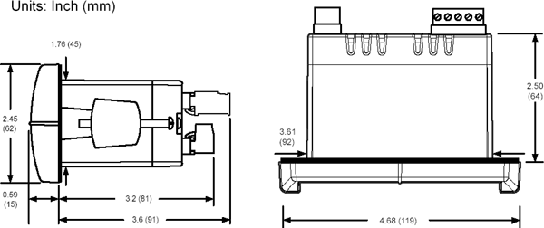
Connections: Removable screw terminals accept 12 to 26 AWG
Enclosure: 1/8 DIN, high impact plastic, 94V-0, color: gray
Weight: 8 oz (227 g) (including options)
UL File Number: E160849; 508 Industrial Control Equipment
Warranty: 3 years parts & labor
Extended Warranty: 1 or 2 years, refer to Price List for details
Voltage Measurement Input
Input: 0 to 300 VDC
Accuracy: ±0.05% of full scale ±1 count
Temperature Drift: 50 PPM/°C from 0 to 65°C ambient
Decimal Point: Up to three decimal places: d.ddd, dd.dd, ddd.d, or dddd
Input Impedance: Greater than 1 MΩ
Calibration Range: An Error message will appear if input 1 and input 2 signals are too close together. Minimum Span: 10 VDC
Serial Communications
Compatibility: EIA-485
Meter Address: PDC protocol: 0 to 99, Modbus protocol: 1 to 247
Baud Rate: 300 to 19,200 bps
Transmit Time Delay: Programmable 0 to 199 ms
Data: 8 bit (1 start bit, 1 stop bit)
Parity: None, even, or odd (Modbus only; PDC protocol does not use parity)
Byte-to-Byte Timeout: 0.01 to 2.54 seconds (Modbus only)
Turn Around Delay: Less than 2 ms (fixed)
Refer to PDC and Modbus Serial Communications Protocol manuals for details.Relays
Rating: 2 Form C (SPDT); rated 3 A @ 30 VDC or 3 A @ 250 VAC resistive load; 1/14 HP @ 125/250 VAC inductive loads
Deadband: 0-100% FS, user selectable
High or Low Alarm: User may program any alarm for high or low
Relay Operation: 1. Automatic (non-latching)
2. Latching
3. Pump alternation control
Relay Reset: User selectable via front panel buttons or PC
1. Automatic reset only (non-latching)
2. Automatic + manual reset at any time (non-latching)
3. Manual reset only, at any time (latching)
4. Manual reset only after alarm condition has cleared (latching)
Automatic Reset: Relays reset when input passes the reset point
Manual Reset: Front panel button, MeterView, Modbus registers
Time Delay: 0 to 199 seconds, on and off delays; programmable
Fail-Safe Operation: Programmable, independent for each relay. Relay coils are energized in non-alarm condition. In case of power failure, relays will go to alarm state.
Isolated 4-20 mA Transmitter Output
Output Range: 1.00 to 23.00 mA typical
Calibration: Factory calibrated 4.00 to 20.00 mA
Accuracy: ±0.1% FS ±0.004 mA
Temperature Drift: 50 PPM/°C
Note: Analog output drift is separate from input driftTransmitter Supply: Isolated 24 VDC ±10% @ 200 mA max
Isolation: 500 V input-to-output or output-to-24 VDC supply; 4 kV input/output-to-power line
External Power: 35 VDC maximum
Output Loop Resistance:| | Loop Resistance |
| Power supply | Minimum | Maximum |
| 24 VDC | 10Ω | 700Ω |
| 35 VDC | 100Ω | 1200 Ω (external) |