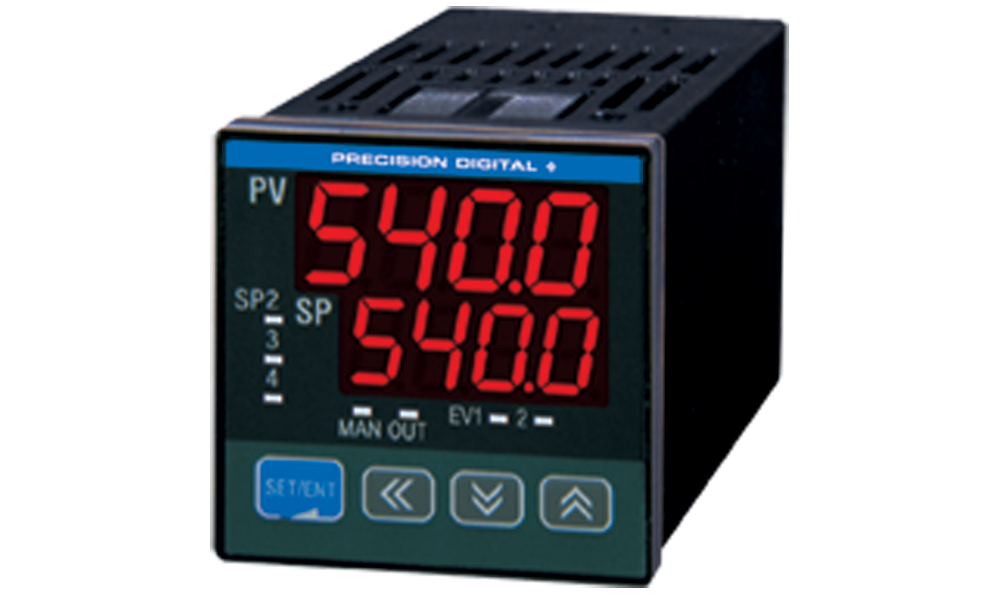


The Nova PD540 is a digital temperature controller with auto-tuning PID capabilities that is available in 1/16, 3/16, 1/8, and 1/4 DIN sizes. Models include standard one-directional control (i.e. heating or cooling) or bi-directional heating and cooling control. One of four user programmable set points may be selected for PID control in the form of time proportional relay on/off output, time proportional voltage pulse output, or 4-20 mA signal control. Its universal input accepts 23 input varieties, including thermocouple, RTD, and voltage inputs, and it can be easily configured for a 4-20 mA input. It is available with up to three (3) relays, two (2) 4-20 mA analog outputs, two (2) digital inputs, and an RS485 serial communication option which includes protocols for master/slave set point control, Modbus® ASCII and RTU, as well as PC software.
Features
- Thermocouple, RTD, & Process Inputs
- High Accuracy Auto-Tuning PID
- Heating & Cooling Models
- Universal Power Supply 100-240 VAC
- Up to 3 Relays & 2 Analog Outputs
- Digital Input Set Point Selection
- RS-485 Serial Communications Option
- Modbus® RTU/ASCII Communications
- Free Operating & Data Logging Software
- IP55 & IP65 Fronts
- 1/16, 3/16, 1/8, 1/4 DIN Sizes
- 3 Year Warranty
General
Display: Dual 4 digits, red LED, -1999 to 9999
| DIN SIZE | PV Display Inch (mm) | SP Display Inch (mm) | Weight oz (g) |
| 1/16 | 0.45 (11.3) | 037 (9.5) | 7.0 (198) |
| 3/16 | 0.55 (14.0) | 0.47 (12.0) | 11.4 (324) |
| 1/8 (H) | 0.78 (19.8) | 0.45 (11.5) | 10.8 (306) |
| 1/8 (V) | 0.54 (13.6) | 0.41 (10.5) | 10.7 (304) |
| 1/4 | 0.81 (20.5) | 0.43 (11.0) | 13.7 (389) |
Front Panel: Panel gasket provided. 1/16 & 1/8 DIN: IP65, 3/16 & 1/4 DIN: IP55
Programming Methods: Four front panel buttons and Modbus
Number of Set Points: Four programmable set points
Noise Filter: Programmable 1 to 120 seconds or off
Display Update Rate: 4/second
Password: Restricts modification of programmed settings.
Non-Volatile Memory: Settings stored for a minimum of 10 years
Power: 100-240 VAC, 50/60 Hz, 10 W
Required Fuse: UL Recognized, 1 A, 250 V, slow-blow
Isolation: 2300 V input/output-to-power line; 4 kV relay output-to-input/output/power line.
Operating Temperature: 10 to 50°C
Storage Temperature: -40 to 85°C
Relative Humidity: 20 to 90% non-condensing
Enclosure: 1/16, 3/16, 1/8(H), 1/8(V), 1/4 DIN; impact-resistant plastic; color: black
Approvals: UL & C-UL Recognized, CE Compliant
UL File Number: E244207; Process Control Equipment
Warranty: 3 years parts & labor
Temperature Inputs
Inputs: Factory calibrated, field selectable: J, K, T, E, B, R, S, L, U, N, W, Platinel II thermocouples,
and 100 Ω platinum RTD (0.00385 or 0.00392 curve)
Cold Junction Reference: Automatic or off
Offset Adjustment: Four programmable input bias zones
Sensor Break: Up or down scale, user selectable; display reads S.OPN; alarm relays will follow the up or
down scale selection.
| Type | Range (°C) | Range (°F) | Accuracy |
Thermocouple Inputs | |||
| K1 | -200 to 1370 | -300 to 2500 | 2500>0ºC: ± 0.1% FS ± 1count <0ºC: ± 0.2% FS ± 1 count |
| K2 | -199.9 to 999.9 | 0 to 2300 | |
| J | -199.9 to 999.9 | -300 to 2300 | |
| T | -199.9 to 400.0 | -300 to 750 | |
| E | -199.9 to 999.9 | -300 to 1800 | |
| B | 0 to 1800 | 32 to 3300 | >400ºC: ± 0.15% FS ± 1 count <400 ºC: ± 5% FS± 1 count |
| R | 0 to 1700 | 32 to 3100 | ±0.15% FS ± 1 count |
| S | 0 to 1700 | 32 to 3100 | |
| L | -199.9 to 900.0 | -300 to 1600 | >0ºC: ± 0.1% FS ± 1 count <0ºC: ± 0.2% FS ± 1 count |
| U | -199.9 to 400.0 | -300 to 750 | |
| N | -200 to 1300 | -300 to 2400 | >0ºC: ± 0.1% FS ± 1 count <0ºC: ± 0.25% FS ± 1 count |
| W | 0 to 2300 | 32 to 4200 | ±0.2% FS ± 1 count |
| Platinel II | 0 to 1390 | 32 to 2500 | ±0.1% FS ± 1 count |
RTD Inputs | |||
| PtA | -199.9 to 850.0 | -300 to 1560 | ±0.1% FS ± 1 count |
| PtB | -199.9 to 500.0 | -199.9 to 999.9 | |
| PtC | -19.99 to 99.99 | -4.0 to 212.0 | ±0.2% FS ± 1 count |
| JPtA | -199.9 to 500.0 | -199.9 to 999.9 | ±0.1% FS ± 1 count |
| JPtB | -150.0 to 150.0 | -199.9 to 300 | |
*Performance within recommended operating conditions (10 to 50 ºC, 20 to 90% RH)
Process Inputs
Inputs: Field selectable: 0.4 to 2.0 V, 1 to 5 V, 0 to 10 V, -10 to 20 mV, 0 to 100 mV. 4-20 mA input requires 100 Ω resistor connected across input terminals (order P/N: PDX-RES1).
Accuracy: ±0.1% FS ±1 count
Decimal Point: Up to 3 decimals: 9.999, 99.99, 999.9 or 9999
Calibration: All inputs are calibrated at the factory
Scale Range: User programmable over entire range
Transmitter Supply: 14 to 18 VDC @ 20 mA; available at terminals OUT2 or OUT3, instead of retransmitting analog output; selection through front panel.
Relays
Ratings: 1 Form C (SPDT) standard; rated 3 A @ 30 VDC or 3 A @ 250 VAC resistive load. 1 or2 Form A (SPST) optional; rated 1 A @ 30 VDC or 1 A @ 250 VAC resistive load.
Relay Operation: Time proportional PID control, on/off control, forward or reverse (fail-safe) alarm, or run status
Cycle Time: 1 to 300 seconds; time proportional PID control only
On/Off Hysteresis: For standard models, 0-10.0% of sensor range for independent high and low hysteresis limit. For heating & cooling models, 0-10.0% of sensor range full hysteresis band.
High/Low Alarm: User may program any alarm for absolute high or low trigger values.
Deviation Alarm: User may program any relay for high, low, or high/low range set point deviation alarm.
Alarm Deadband: 0-100% FS, user selectable
Alarm Delay: 0 to 99 minutes and 59 seconds
Reverse Operation (Fail-Safe): Programmable, independent for each alarm. Relay coils are energized in non-alarm condition. In case of power failure, relays will go to alarm state.
Forward Operation: Relay coils are energized in alarm condition. In case of power failure, relays will go to non-alarm state.
Auto Alarm Initialization: Normal and standby operation independent for each alarm. Normal alarms will reflect the state of the input to the controller at all times. Standby alarms will not trigger if the change to alarm state is a result of power up cycle, set point change, or alarm configuration change.
Run Status: Relays will energize when PID outputs are running.
Analog Outputs
Scaling Range: Retransmitting 4-20 mA outputs can be scaled for any display range.
Accuracy: ±0.1% FS
Availability:1/16 & 3/16 DIN: 1 standard, 1 optional 1/8 & 1/4 DIN: 2 standard
Output Operation: 4-20 mA PID control, time proportional voltage pulse PID control, or 4-20 mA retransmitting
Ratings: Continuous 4-20 mA PID or retransmitting: 600 Ω max Time Proportional PID: 15 VDC pulse high, less than 0.1 VDC pulse low; 600 Ω minimum, current limited at 30 mA
Cycle Time: 1 to 300 seconds; time proportional PID control only
Power: Internally powered 4-20 mA output
Isolation: 500 V input-to-output
Output Loop Resistance: 600 Ω max
Digital Inputs
Configuration Two contacts, two operating modes
Contacts: Normally open switches (external excitation not required) or open collector transistor
Open Circuit Voltage: Approximately 5 VDC
Logic Levels: LO = 0 to 0.8 VDC, HI = 4.7 to 28 VDC
Operation Modes: Mode 1: Control output run or stop, selection of set point 1 or 2. Mode 2: Selection of set points
1 to 4.
Serial Communications
Compatibility: EIA-485
Protocol: PC, Modbus (ASCII, RTU), Sync (Master/Slave SP Control)
Address: 1 to 99 (Max 31 units connected)
Baud Rate: 600 to 19,200 bps
Transmit Time Delay: 0 to 100 ms
Data: 7 or 8 bit, automatic when using Modbus protocol
Stop Bit: 1 or 2
Parity: None, even, or odd
Nova Multi-Monitoring PC Software
Any Nova Controller with the serial communications option can be configured to interface with the Nova Multi-Monitoring PC software. Up to 30 controllers can be monitored and operated, and each can use independent data logging.
- Easy to Set Up and Use
- Connect up to 30 Nova Controllers
- View PV, SP, and Alarm Status Simultaneously
- Control Set Points
- Log, View, and Save Data in Spreadsheet Files
- Free Download (click here)
Specifications
System Requirements: Windows® 95\98\ME\2000\XP\Vista\7
Communications: An RS-232 to RS-485 or USB to RS-485 converter may be used for communication with a PC and Nova Multi-Monitoring Software.
Number of Units: Up to 30 Nova Controllers
Baud Rate: 9,600 to 19,200 bps
Data Logging: Graph and save data as .hdr format. Each controller saves graphs independently. Data exportable in spreadsheet format.
Logging Interval: 1 second to 24 hours
Simultaneous Monitoring
Simultaneously monitor up to 30 Nova Controllers and view the PV, SP, and alarm status for all connected controllers. The main view screen also displays the basic model numbers of all connected units. Any series
of Nova Controllers with the serial communications option may be monitored with this software.
Simultaneously View Up to 30 Nova Controllers
Remotely Control Set Points
Program each of the 4 set points through a detailed operation screen available for every connected controller. In addition, control outputs can be set to run or stop, auto tuning enabled, and automatic or manual control established.
Monitor and Control Common Parameters
Data Acquisition
PV and SP data can be logged independently for each unit. This data can be graphed using the Data Viewer for quick and clear analysis. Logged data can be exported into spreadsheet format.
View Logged Data Graphs and Export Data
PD540 & PD541 Connections
PD542 & PD543 Connections
PD544 & PD545 Connections
PD546 & PD547 Connections
PD548 & PD549 Connections
PD540 & PD541 Cutouts
1/16 DIN (48 x 48)
PD542 & PD543 Cutouts
1/8 DIN (H) (96 x 48)
PD544 & PD545 Cutouts
3/16 DIN (72 x 72)
PD546 & PD547 Cutouts
1/8 DIN (V) (48 x 96)
PD548 & PD549 Cutouts
1/4 DIN (96 x 96)
Choose Your Options

Applicable Meter Types for PDC Enclosures
| Type A | Type B | Type C | Type D | Type E | Type F | Type G | Type H |
|---|---|---|---|---|---|---|---|
 |  |  |  |  |  |  |  |
| PD690 | PD542 PD543 | PD603 PD644 PD743 PD765 PD6602 PD6603 PD6604 PD6606 PD6607 PD6608 PD6622 PD6624 PD6626 PD6628 | PD138 PD154 PD158 PD520 | PD6000 PD6001 PD6060 PD6080 PD6081 PD6088 PD6089 PD6100 PD6200 PD6210 PD6262 PD6300 PD6310 PD6363 PD6400 PD7000 | PD530 | PD510 | PD420 |