

Features
- NEMA 4X Panel Mount Multivariable Controller
- Convenient Display, Control, & Alarm of Multiple 4-20 mA, Pulse, & Modbus Inputs
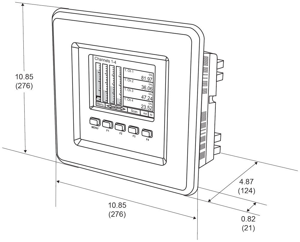
- Numeric & Bargraph Color Display (320 x 240 pixels) 5.7" (145 mm)
- Sunlight Readable Display, White Backlight
- Isolated 24 VDC Transmitter Supplies 200 mA / Analog Input: 1,600 mA Max
- 99 Channels, 32 Totalizers, 30 Timers, & 199 Modbus Inputs
- 64 High & Low Alarms, Combine Multiple Alarms Into Logic AND & OR Alarms
- Simulation & Manual Control Modes for Testing and Setup
- Modular Design for Inputs & Outputs Flexibility
- Up to (28) 4-20 mA Isolated Inputs or Pulse Inputs
- Up to (25) 10 Amp Form C Relays (With Eight Analog or Pulse Inputs)
- Up to (25) Isolated 4-20 mA Outputs (With Eight Analog or Pulse Inputs)
- Operating Temperature Range: -25°C to 55°C (-13 to 131°F)
- Pulse, Analog, & Modbus Input Flow Rate / Total / Grand Total Capability
- 50-Point Linearization, Square Root, and Exponent for Open Channel Flow
- Round Horizontal Tank Volume Calculation; Just Enter Diameter & Length
- Open Channel Flow Math Formulas for Weirs & Flumes
- Multi-Pump Alternation Control or On / Off Control with Random Varying Set Point
- Programmable Displays, Function Keys & Digital Inputs
- Math Functions: Sum, Diff, Average, Multiply, Divide, % Efficiency, & More
- Modbus Client (Master) & Snooper / Server with 99 Programmable Outputs
- Direct Modbus PV Inputs – Snooper / Server Mode
- Modbus Spoofer Feature to Replace Servers Removed from Network
- RS-485 Serial Communication with Modbus RTU / ASCII & Ethernet TCP/IP
- USB Data Logger Feature: Up to 8 Log Files with up to 12 Parameters Each
- Input Power Options: 90-264 VAC or 24 VDC
- 20) Screens with up to Eight PVs Each
- ConsoliDator+ Configuration Software
- Type 4X, IP66 Front – Field Enclosures Available
- Auto-Tune PID Control for Multiple Control Loops
- PID Control with Analog, Digital, or Relay Outputs
- Digital Selector Switch (HOA) Function to Route Inputs & Outputs
- Stainless Steel Sun Hood Accessory Available
- 3-Year Warranty
Overview
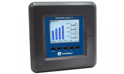
The ConsoliDator+ is a multivariable controller that is both easy to use and satisfies a wide variety of process display, alarm, and control applications. It accepts 4-20 mA inputs, flow meter pulse inputs, digital inputs, and Modbus inputs and displays them in both numeric and bargraph format on a large, 5.7" color display. It can be equipped with multiple relays with user-definable actions, 4-20 mA outputs, digital outputs, Modbus RTU & ASCII, Modbus Enron, and Ethernet Modbus TCP/IP protocol communication. Additionally, the controller is equipped with up to 30 timers that can be used to control many processes or events.
Two standard new features have been added to the version 2.300 release:
- Auto-Tune PID Control
- Digital Switches (HOA)
The ConsoliDator+ takes full advantage of its color display by allowing the user to customize screen colors for bargraphs, alarm conditions, and input channels.
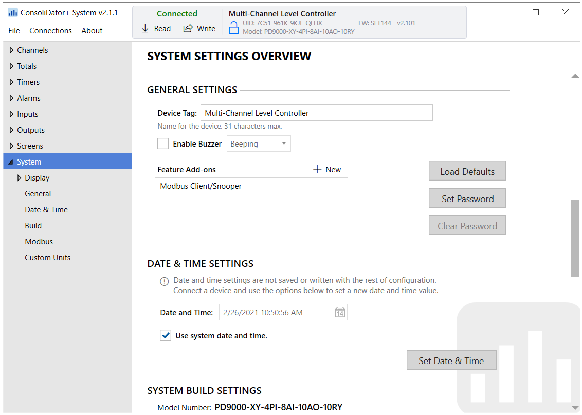
All this functionality is easily programmed using the free software or via the front panel pushbuttons. Choose the model that best suits your application, from monitoring only to fully loaded controllers with an extensive combination of inputs, outputs, and communication protocols. The standard product offering is listed in the ordering guide and other models are available for special order. The Modbus Client, Snooper, & Spoofer and USB Data Logger Add-On features expand the functionality of the ConsoliDator+.
The ConsoliDator+ has been Certified by Underwriters Laboratory (UL & C-UL) for use in ordinary locations (electrical safety) and in Div 2 hazardous area locations (nonincendive).
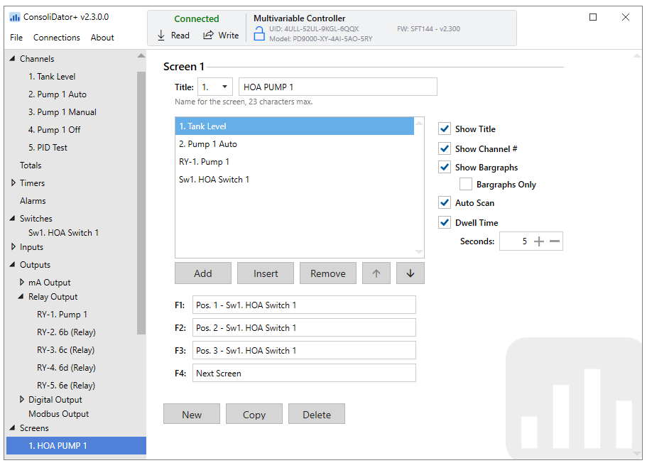
Screens
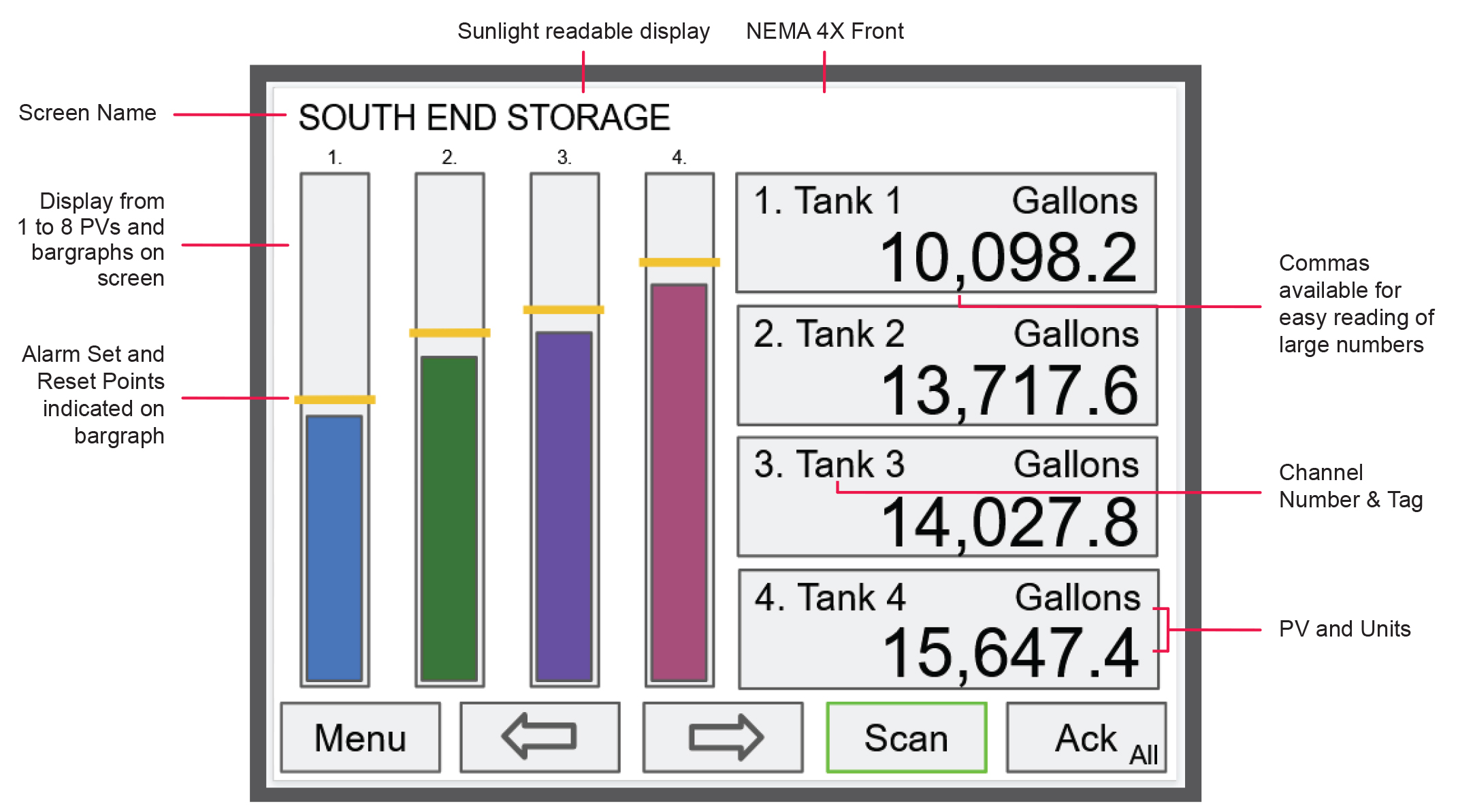
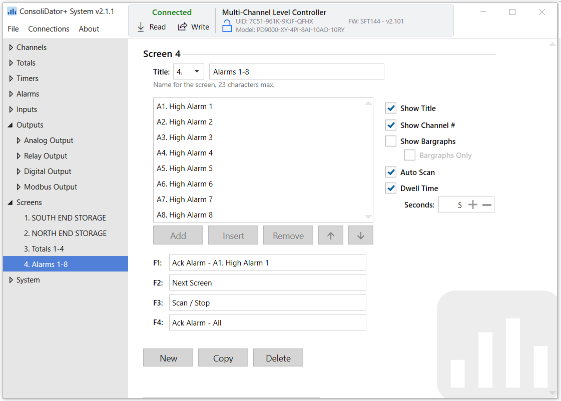
The ConsoliDator+ can be programmed to display the data on up to 20 different screens in a variety of formats and colors, with and without bargraphs. The following screens show a typical main screen and channel details screen:
Main Screen
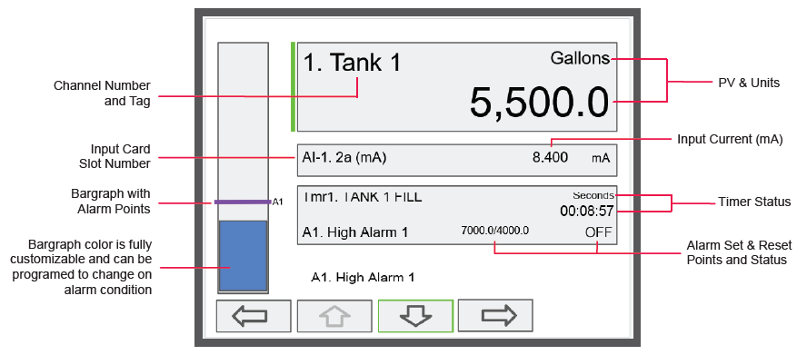
Channel Details Screen
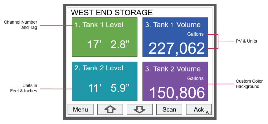
Screen with Feet & Inches Units
No More Sun Glare On Your
Multivariable Controller Display!

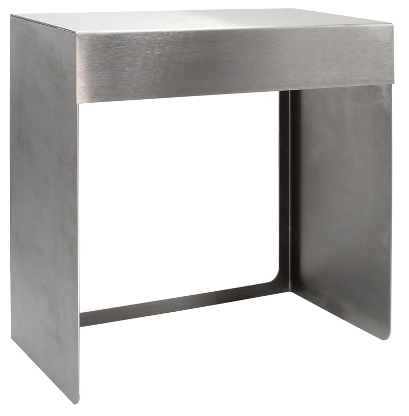
New PDA9000SH Sun Hood
The PDA9000SH Stainless Steel Sun Hood improves the readability of the PD9000 ConsoliDator+ Multivarialble Controller when it is mounted in direct sunlight by shading the instrument from the sun. The Sun Hood is made from 18 gauge 316 stainless steel and mounts between the PD9000 controller and the enclosure cover/door. In addition, the attached gasket is installed between the Sun Hood and the enclosure cover/door to provide a NEMA 4X seal. The whole assembly is held in place by the 12 mounting screws provided with the ConsoliDator+ Controller.
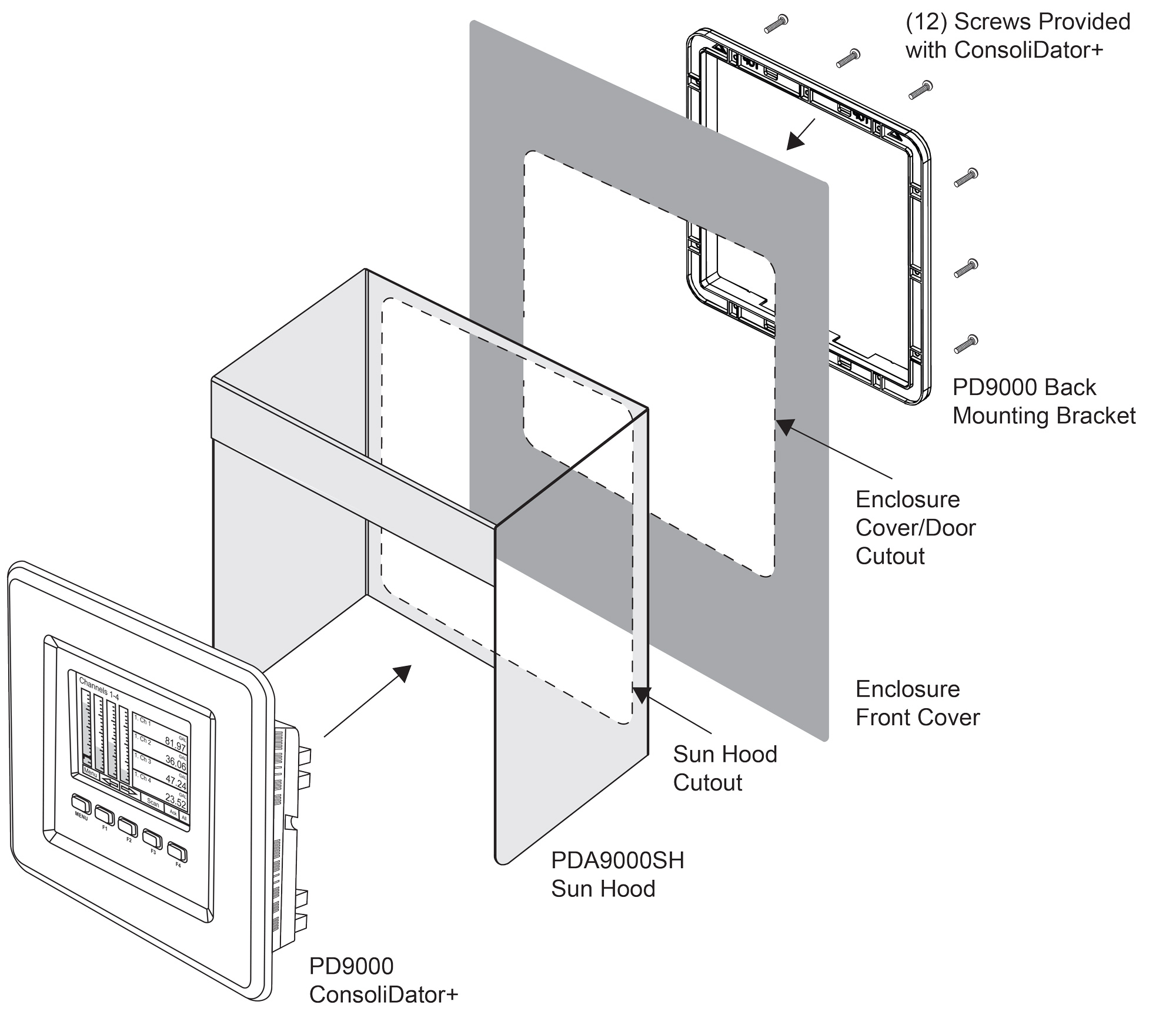
- Provides Shade for PD9000 ConsoliDator+ Multivarialble Controller
- Made from 18 Gauge 316 Stainless Steel
- Easy Mounting Requires no Drilled Holes in the Enclosure Cover/Door
- Includes Gasket to Maintain NEMA 4X Seal
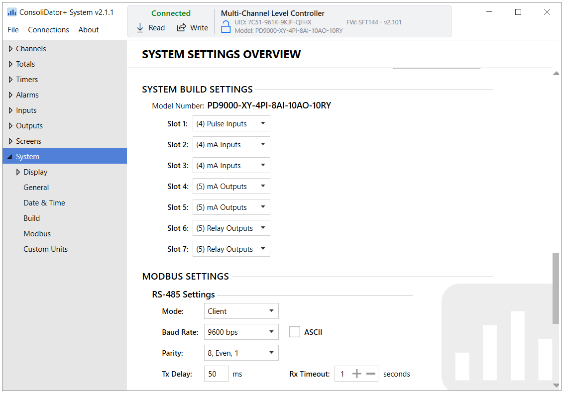
Inputs & Outputs
The back panel is labeled with the I/O boards that were installed at the factory. The removable connectors are labeled with the connection signal for each terminal. The following diagram shows what the back of the model PD9000-6G-4PI-8AI-10AO-10RY-E looks like. This model is powered from 90-264 VAC, it accepts (4) pulse and (8) analog inputs and has (10) 4-20 mA outputs and (10) relays. (5) digital inputs, (4) digital outputs, RS-485 serial capability and USB connections are standard on all ConsoliDator+ models. Ethernet is an option.
If all Input / Output slots are used exclusively for one function, the ConsoliDator+ can accept up to (28) isolated 4-20 mA inputs, (28) pulse inputs, (25) isolated 4-20 mA outputs, or (25) relays.
If used as a Modbus Client, Snooper, or Server only: It can have (35) 4-20 mA outputs, 30 relays,
or (20) 4-20 mA outputs and (15) relays.
If used as a Modbus Client, Snooper, or Server only: It can have (35) 4-20 mA outputs, 30 relays,
or (20) 4-20 mA outputs and (15) relays.
Units are powered from AC or DC according to the power option ordered (AC: -6 or DC: -7).
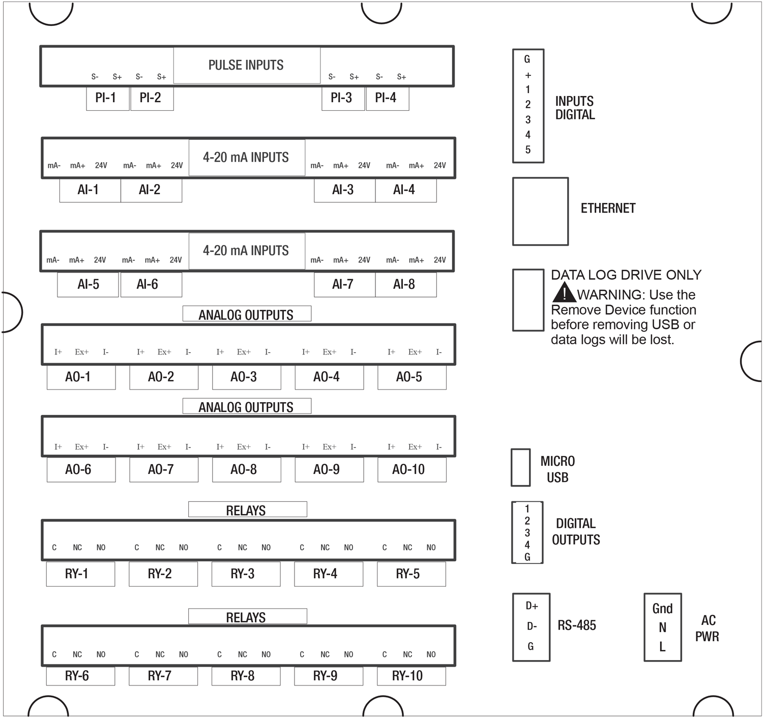
Connection Terminals for a PD9000-6G-4PI-8AI-10AO-10RY-E
- Each 4-20 mA input has its own isolated 24 VDC power supply to power the transmitter.
- Each 4-20 mA output has its own isolated 24 VDC power supply to power the output loop.
- Each relay is Form C and rated at 10 A.
- Input / output connections are made to removable screw connectors.
- Every ConsoliDator+ has five digital inputs (additional digital inputs can be obtained by using the Pulse Inputs).
- Every ConsoliDator+ has four digital outputs.
- Every ConsoliDator+ has RS-485 with Modbus.
- All ConsoliDator+ models can be powered from either AC or DC Power.
- The Data Log Drive is used for the Data Logger Add-On feature.
- Ethernet with Modbus TCP is an option.
- Micro USB is used for programming the ConsoliDator+ with Free Software.

- Use copper wire with 60°C or 60/75°C insulation for all line voltage connections. Observe all safety regulations. Electrical wiring should be performed in accordance with all applicable national, state, and local codes to prevent damage to the controller and ensure personnel safety.
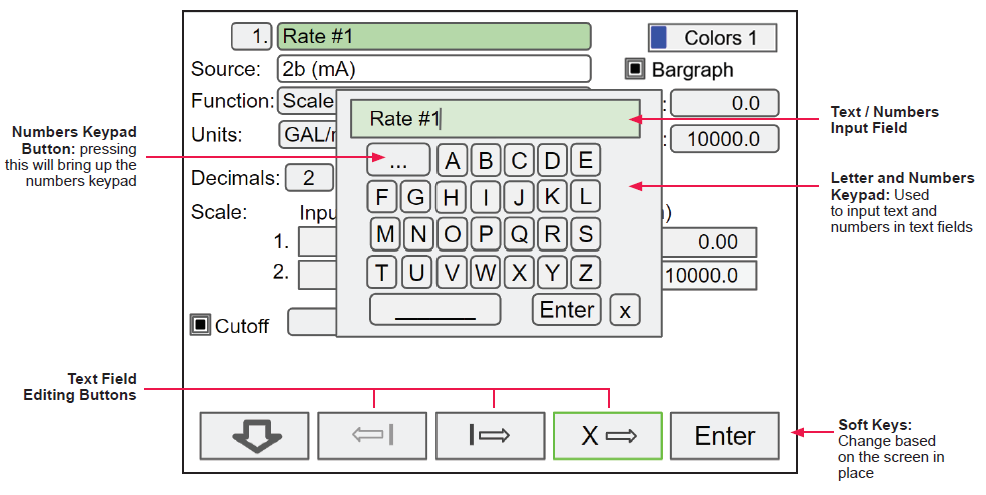
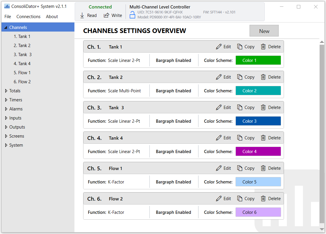
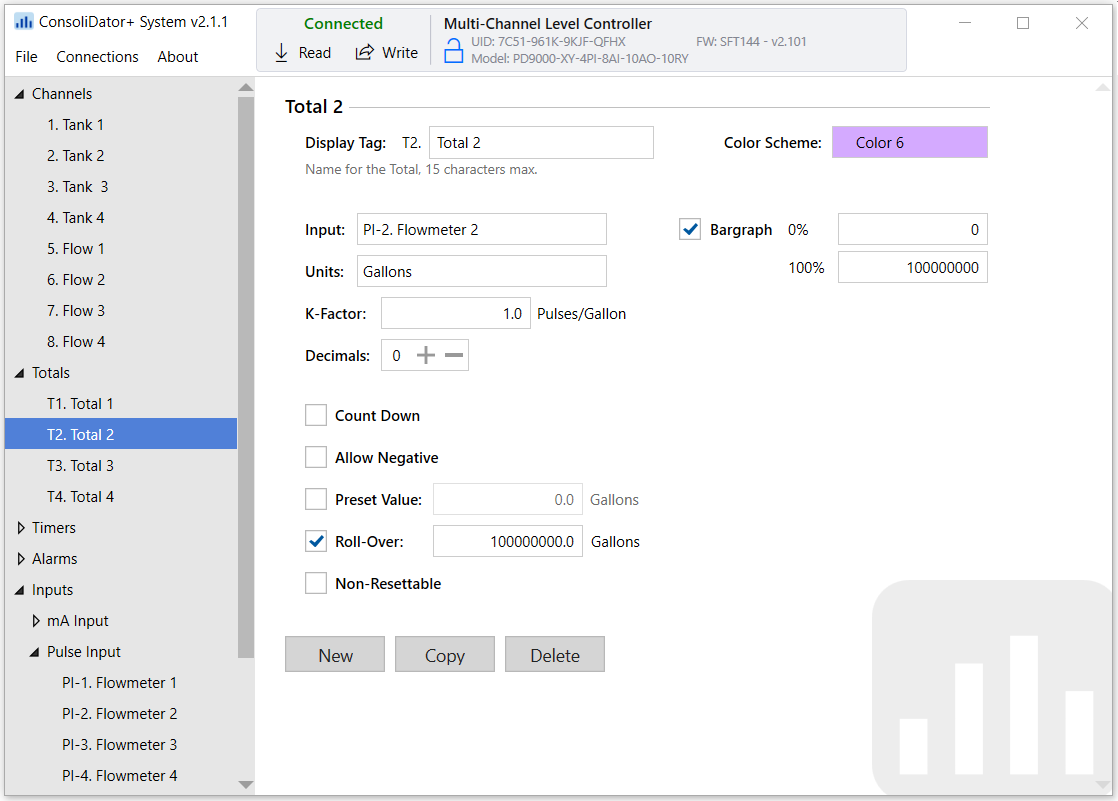
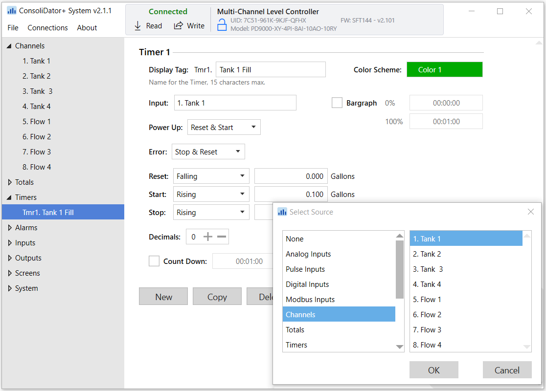
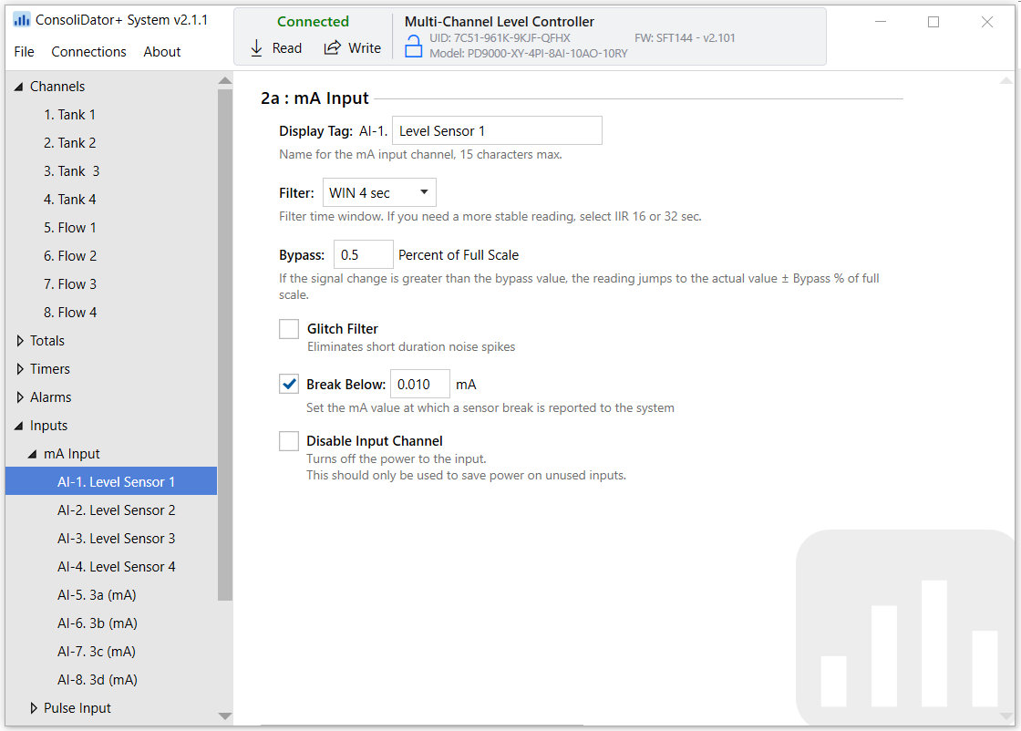
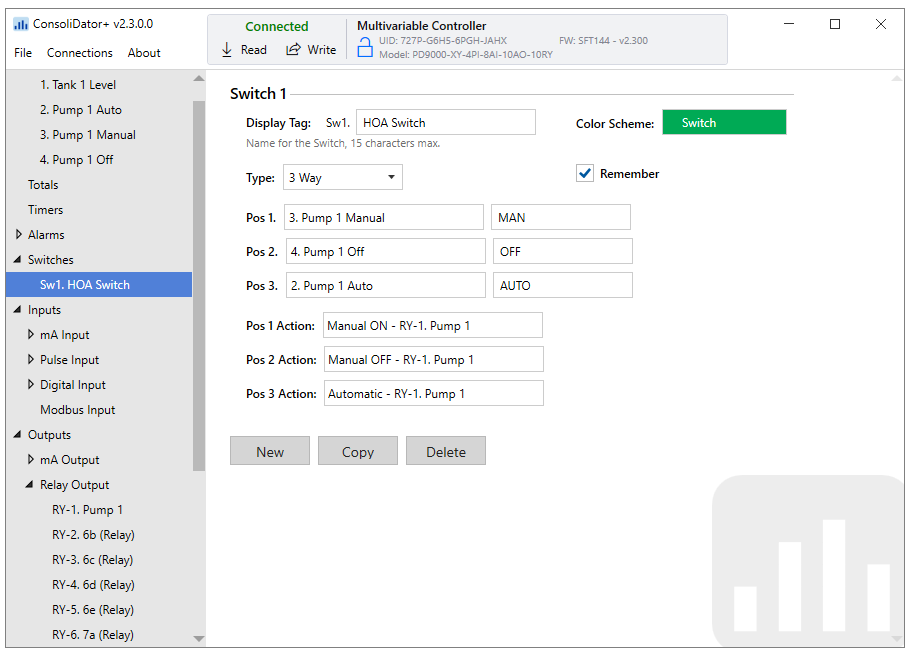
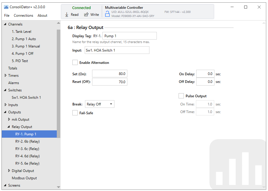
Setting Channel Parameters
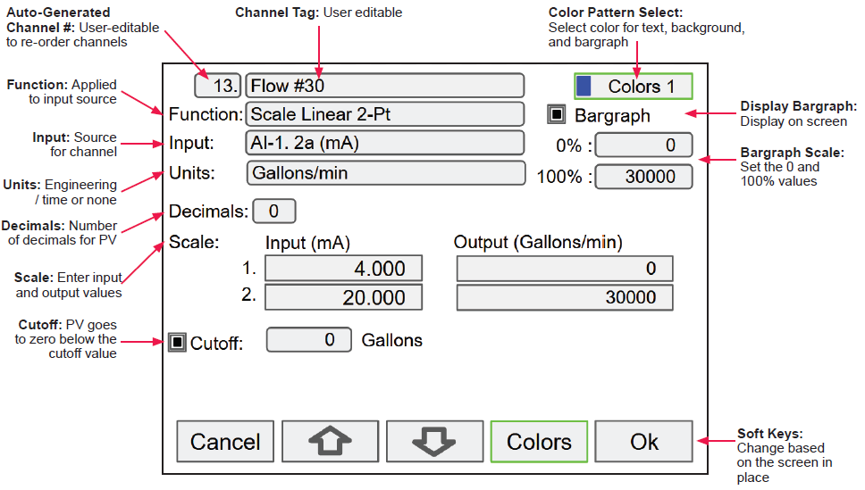
What makes the ConsoliDator+ easy to program is its intuitive setup screens. As shown in the first image below, the setup screen allows you to see all the relevant information you need when creating or editing a channel - all on one screen! When creating a new channel, the channel number is auto-generated for you. All you have to do is populate the appropriate fields such as the channel tag name, function, input, and units.
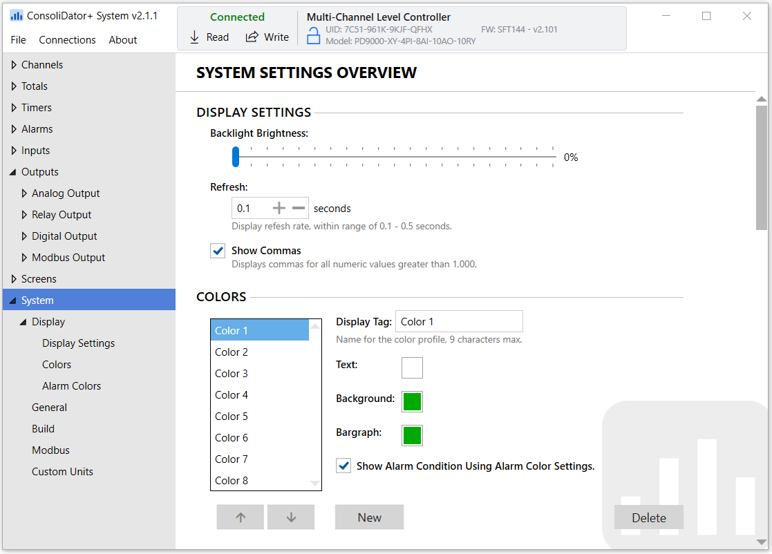
Scaling the inputs and outputs, selecting number of decimals, and turning the bargraph on/off and inputing its values are also programmed from this screen. Multiple colors can also be selected for the text, background and bargraphs to customize the look of the display screens.
During programming, the soft keys will change based on the screen in place. For instance, pressing the edit key will bring up the letters/numbers keypad and appropriate navigation keys will appear (Shown in the bottom image). See the PD9000 manual for details on setup and programming.
Individual Channel View
To view the details of any channel, press Menu and then press View – Channel. Select the channel of interest. Navigate through the different items using the navigation keys. A green bar indicates the selected item, press the R-key to step into and see more details about the inputs and outputs related to the channel in view.
In the following examples, the screens show all the parameters associated with Channel 1 including analog input, slot number and its current value, setpoints and status of alarms, and analog output and its mA value. The bargraphs in each of these screens examples represent the current value in gallon units.
 Alarm set points are indicated
by horizontal lines.
Low & High Alarm Indication
If applicable, alarms may be acknowledged, and totals may be reset from the channel view screens. The alarm set points are indicated by a line at the corresponding value on the bargraph. Color selection for alarm conditions can be done in the Setup – Alarm menu or in the System – Display menu.
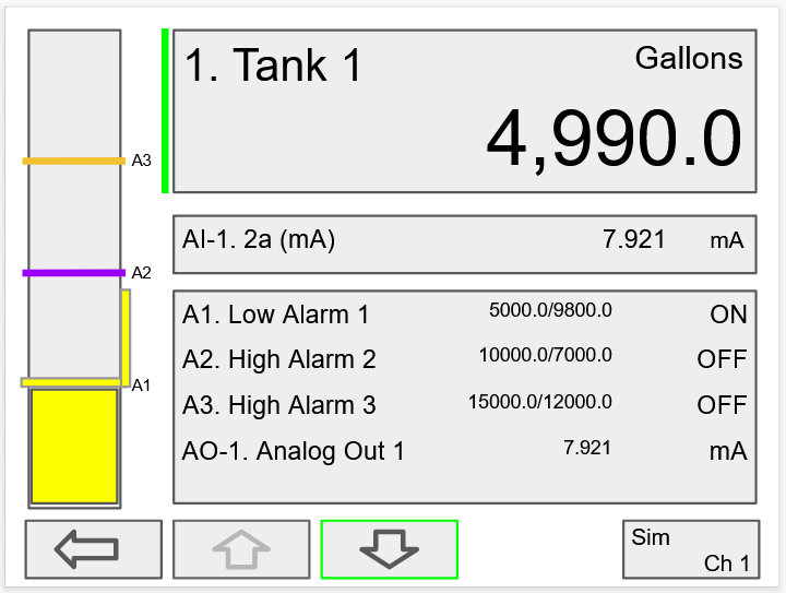
Active Low Alarm: Indicated by horizontal and vertical lines. The top of the vertical line is the reset point of the low alarm. The low alarm is indicated on the right side of the bargraph.
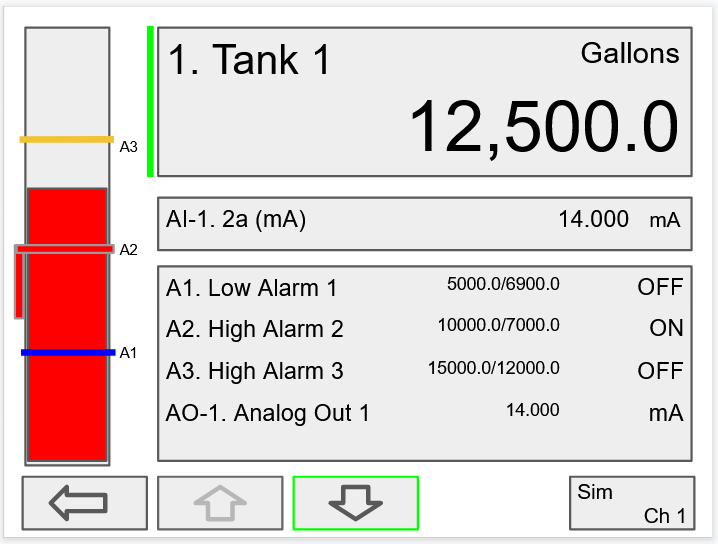
Active High Alarm: Indicated by horizontal and vertical lines. The bottom of the vertical line is the reset point of the high alarm. The high alarm is indicated on the left side of the bargraph.
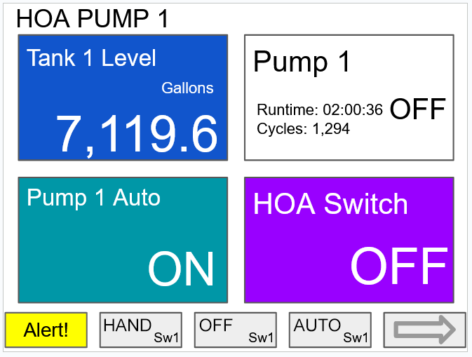
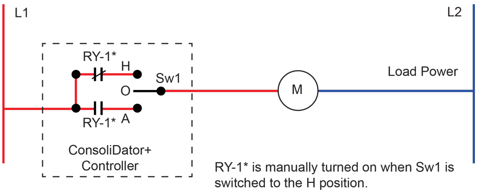
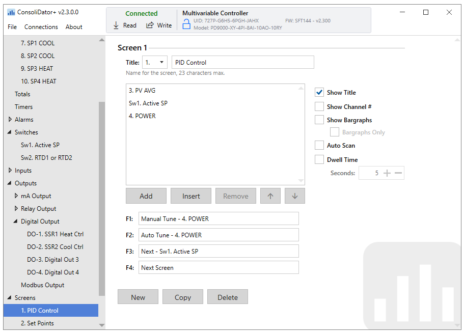
HOA Screen View
The image on the right shows the screen displaying Tank level in gallons, Alert! message indicating the pump has been turned off manually, HOA switch is the Off position, Pump 1 relay shows the runtime and number of cycles.
The HOA switch can be switched to automatic control by pressing the F4 key (AUTO).
Block Diagram for HOA Switch
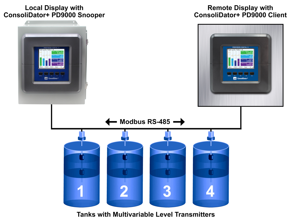
Modbus Client, Snooper & Spoofer Add-On Features
The ConsoliDator+ Multivariable Controller supports Modbus RTU, Modbus ASCII, Enron Modbus, and Ethernet Modbus TCP/IP. The Server mode is a standard ConsoliDator+ feature; it responds to requests and accepts writes from a Modbus client.
The ConsoliDator+ is now available with Modbus Client, Snooper, and Spoofer capabilities and has the ability to scan and display up to 199 Modbus registers. This feature can be “unlocked” on any ConsoliDator+ purchased after February 15, 2021 by purchasing the PDK9000-M1 Key for $500 and entering the Key value into the ConsoliDator+.
Client Mode
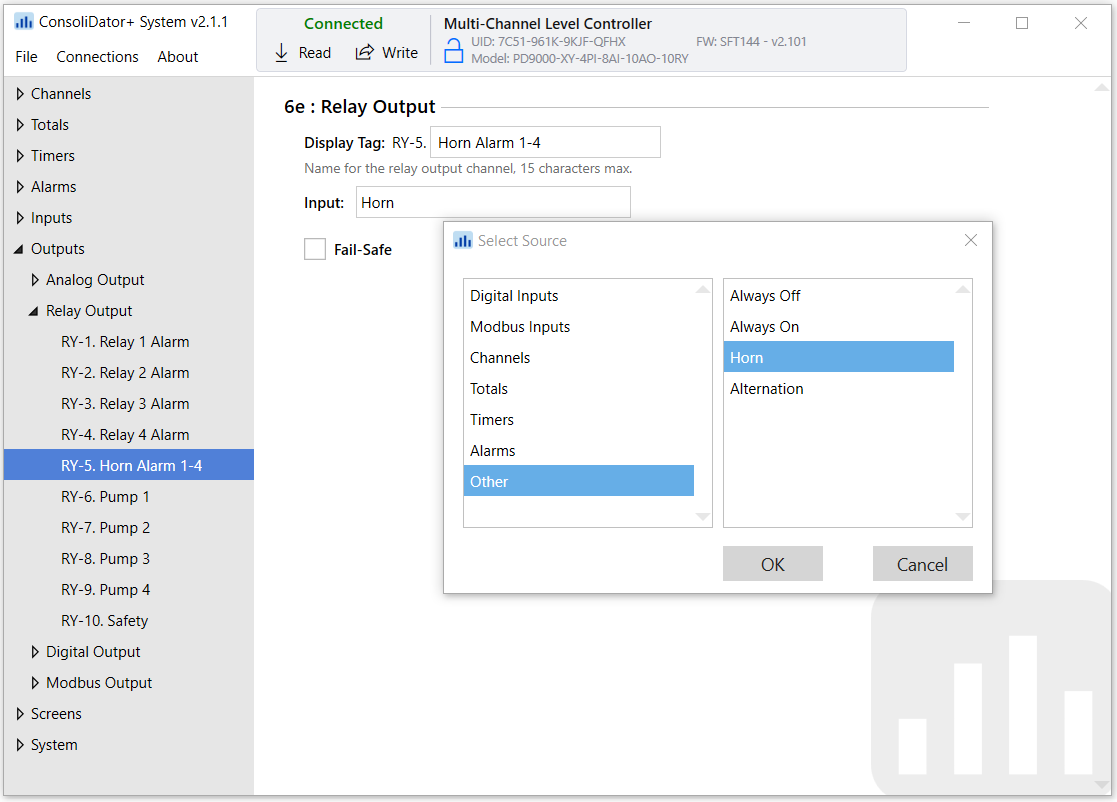
The Client mode can request process variables from server devices; the input variables can be scaled, combined with other variables using math functions, and they can be written to other server devices using the Modbus output functions. The controller can request up to 199 Modbus values, as inputs from other Modbus devices. The inputs can be used as the source for channels, math functions, alarms, relay control, etc.
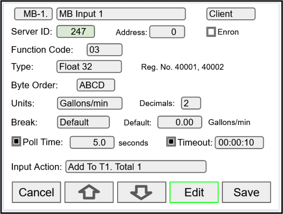
Modbus inputs setup screen for Client mode
Snooper Mode
The Snooper mode can listen and read the process variables being transmitted on the RS-485 bus without causing any disruptions to the network. The controller can read up to 199 Modbus values, as inputs from other Modbus devices being polled by a Modbus Client. The inputs can be used as the source for channels, math functions, alarms, relay control, etc.
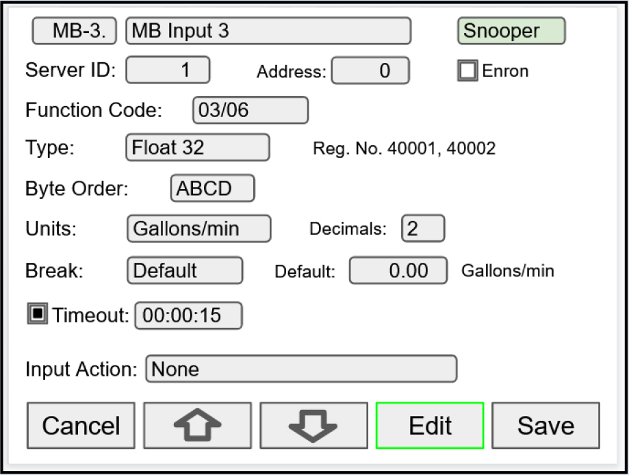
Modbus inputs setup screen for Snooper mode
Spoofer Mode
The Spoofer mode is designed to replace existing Modbus Servers without requiring changes to the Client configuration. Each process value can be assigned a specific Device ID and Register Number to mimic the original Client configurations.

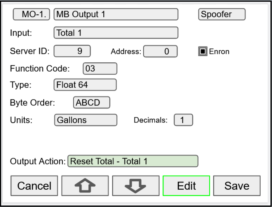
Modbus Output setup screen for Spoofer mode
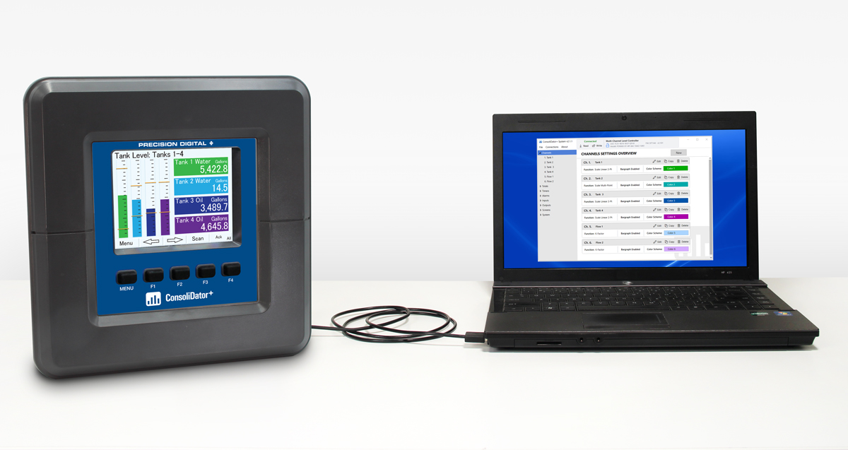
ConsoliDator+ USB Data Logger Add-On Feature
Setup Data Log
Setup New Data Log
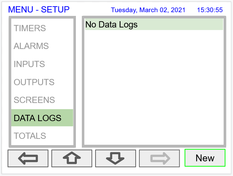
- Navigate to the Data Logs menu
- Press the New key (F4) to create a new log
- An untitled log is created

| Log #: | Enter log file name |
| Add: | Add items to be logged |
| Start / Stop: | Control the log start & stop |
| Enable Switch: | Select an additional log control |
| Log Trigger: | Trigger log on a specific event |
| Log Interval: | Log at the specified interval |
| Log with Units: | Each log entry will have the corresponding engineering units |
 Do not change the units for totals, while the data logger is running; the accumulated total will not be converted to the new units and the reflected value will not be accurate.
Add Items to Be Logged
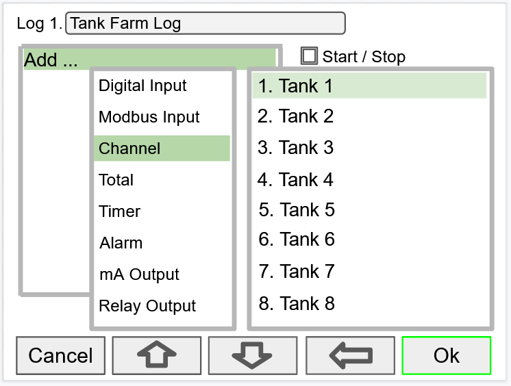
2. Digital Inputs
3. Modbus Inputs
4. Channels
5. Totals
6. Timers
8. mA Outputs
9. Relay Outputs
10. Digital Outputs
11. Modbus Outputs
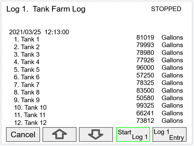
Setup Log Start / Stop

The Start / Stop function is available in the View Log menu via the function keys.
The Start / Stop function can be activated with:
- Screen F1-F4 function keys
- Digital inputs
- Modbus inputs
- Modbus outputs
- Channel Control: Schedule, Sampler
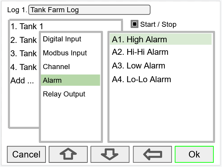
Setup Log Enable Switch

The Enable Switch input can be:
- Digital input
- Modbus input
- Channel
- Alarm
- Relay Output
Setup Log Trigger
The Log Trigger input can be:
- Digital input
- Modbus input
- Channel
- Alarm
- Relay Output
Setup Log Interval & Log Units
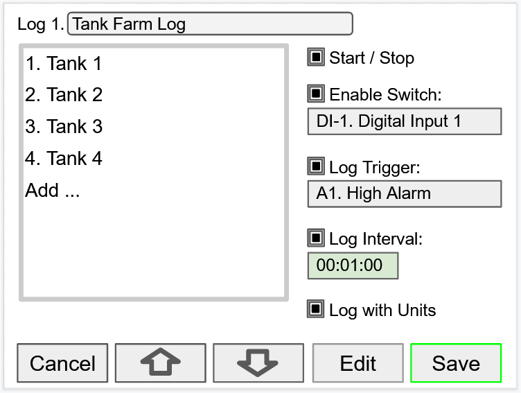
In this example the log must be started, and the digital input 1 must be on to log the tanks volume every minute.
To log continuously without the need to start or enable the log, deselect the Start / Stop and the Enable Switch settings.
If engineering units are not needed, deselect the Log with Units setting.
Setup USB Drive
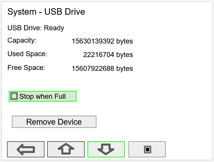
- USB Drive Status
- Capacity
- Used Space
- Free Space
If Stop when Full is not selected, the oldest block of data will be deleted to make room for new data.

Safely Remove Flash Drive
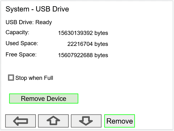
Go to the System – USB Drive screen, navigate to the Remove Device button using the down arrow key, then press the Remove key.
This procedure allows the USB drive to finish writing any log data in progress and prevent the lost or corruption of data.
View Data Logs
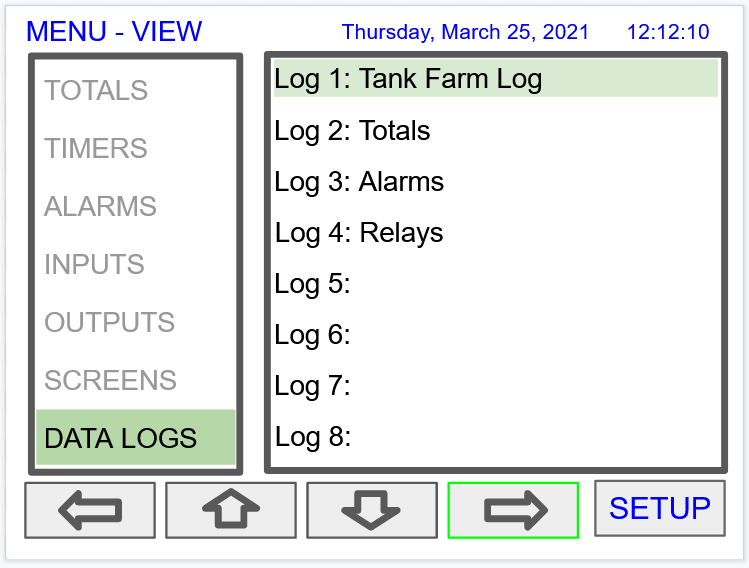
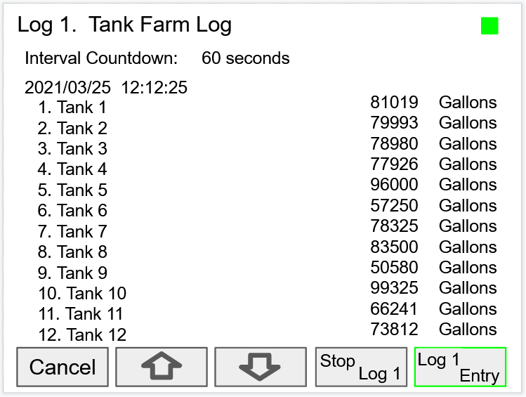
After the log is started, the system will capture the first log according to the log setup selected.
The Log Entry key allows the user to capture a snapshot of the process any time.
There is no provision for viewing previous log records on the screen. The flash drive must be removed and connected to a computer to download the saved logs.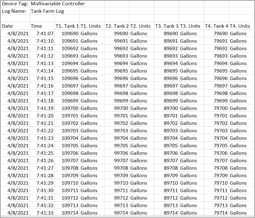


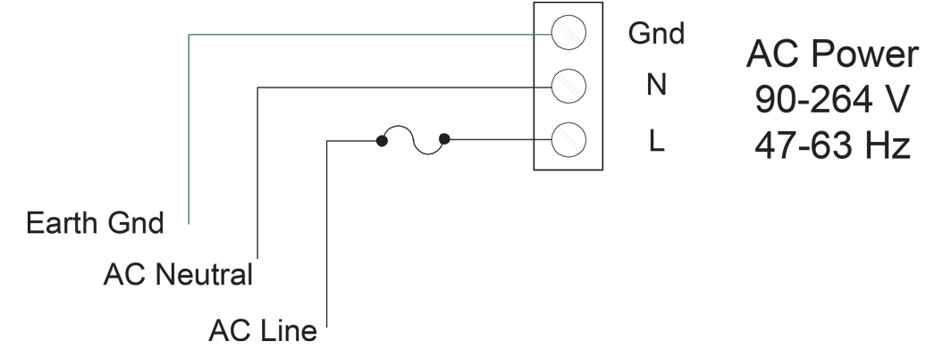 AC Power Connections
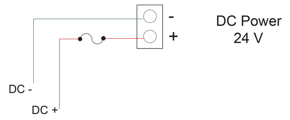 DC Power Connections
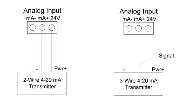 Transmitters Powered by ConsoliDator+ Isolated 24 VDC Power Supply
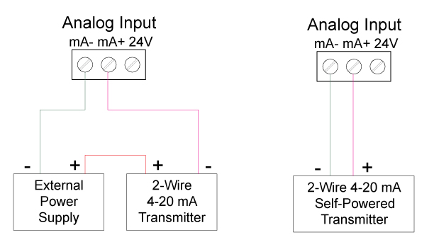 Transmitter Powered by External Supply or Self-Powered
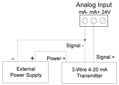 Three-Wire Transmitters Powered Externally
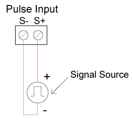 Flow Meter Pulse Input Connections
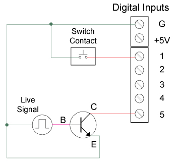 Digital Input from Switch Closure and Live Signal
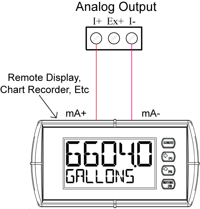 Active 4-20 mA Output Powered by ConsoliDator+
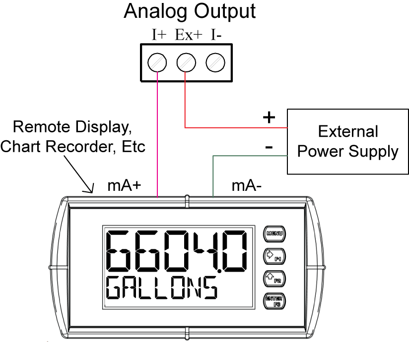 Passive 4-20 mA Output Powered by External Supply
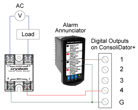 Digital Outputs Driving 5V Solid State Relay
and Alarm Annunciator
Digital Outputs Driving 5V Solid State Relay
and Alarm Annunciator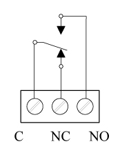 Relay Connections
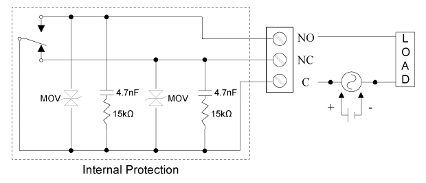 AC and DC Internal Inductive Load Protection
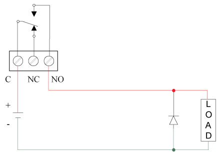 Low Voltage DC Loads Protection
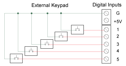 External Keypad Connections