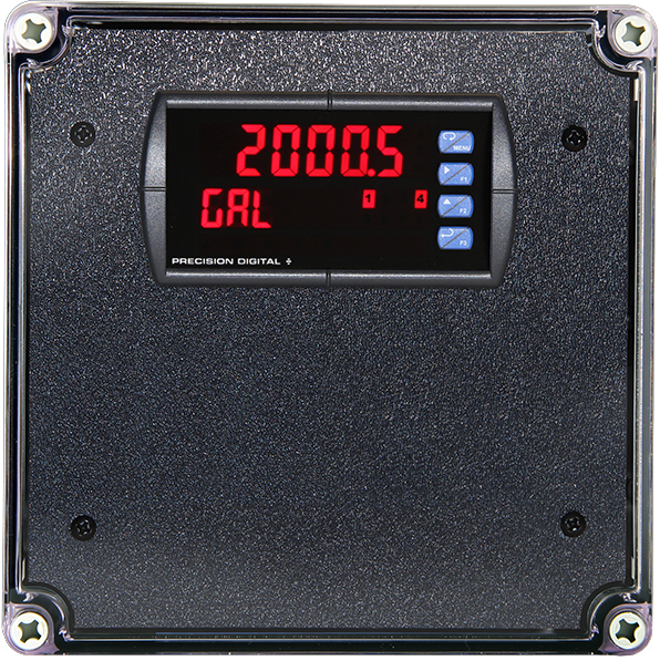
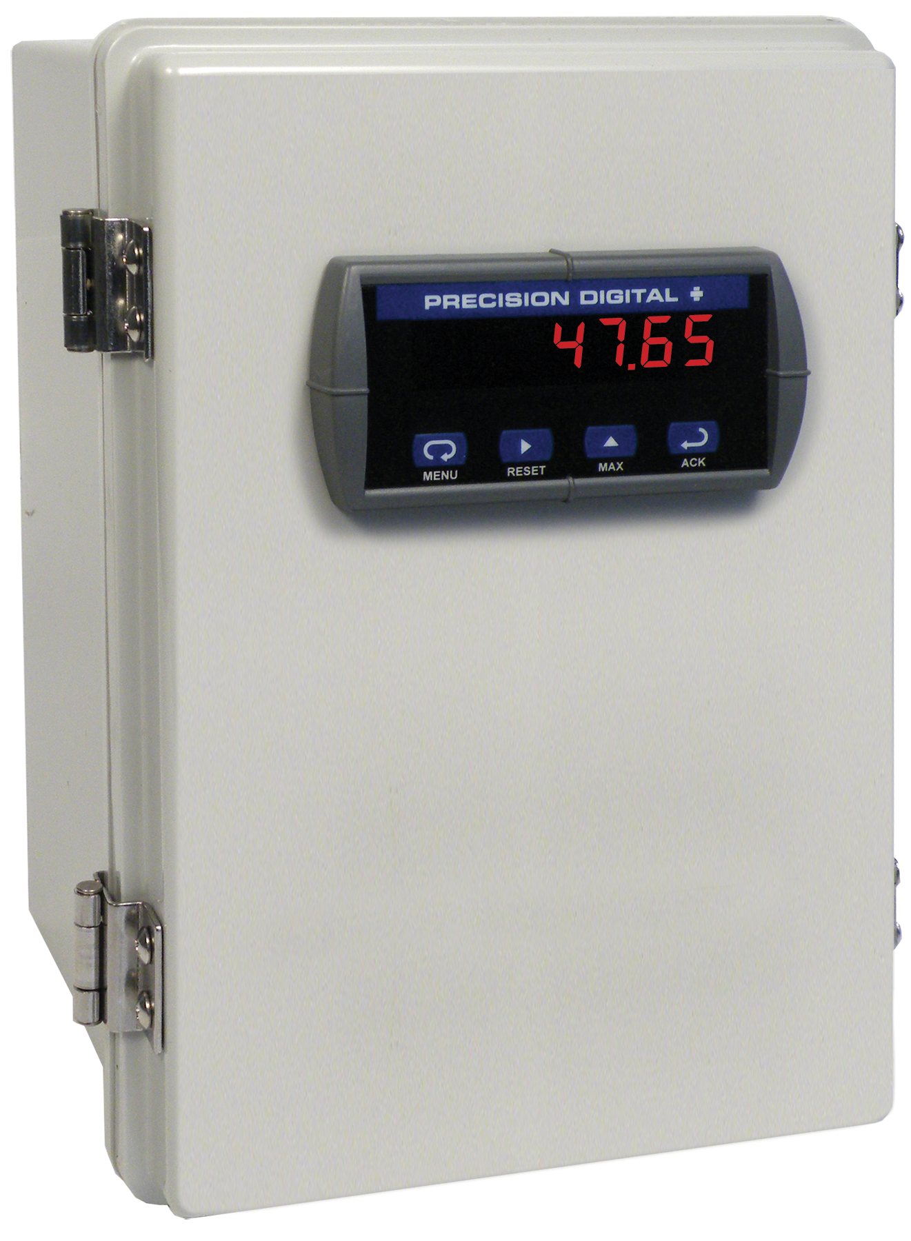
PDA3411-1
Plastic UL Type 4X Enclosure with (1) Horizontal 1/8 DIN Cutout
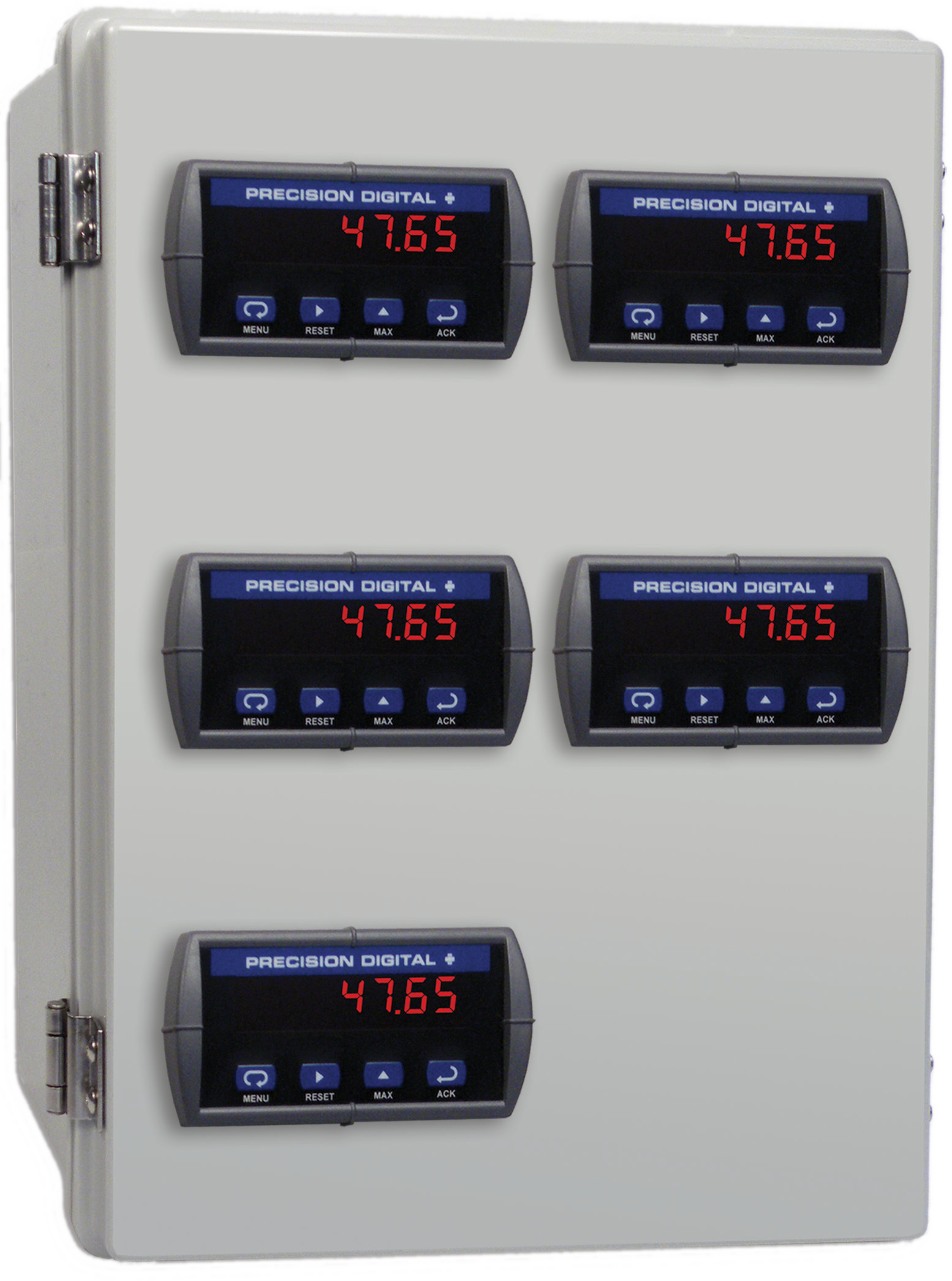
PDA2305
Plastic UL Type 4X Enclosure with (5) Horizontal 1/8 DIN Cutouts
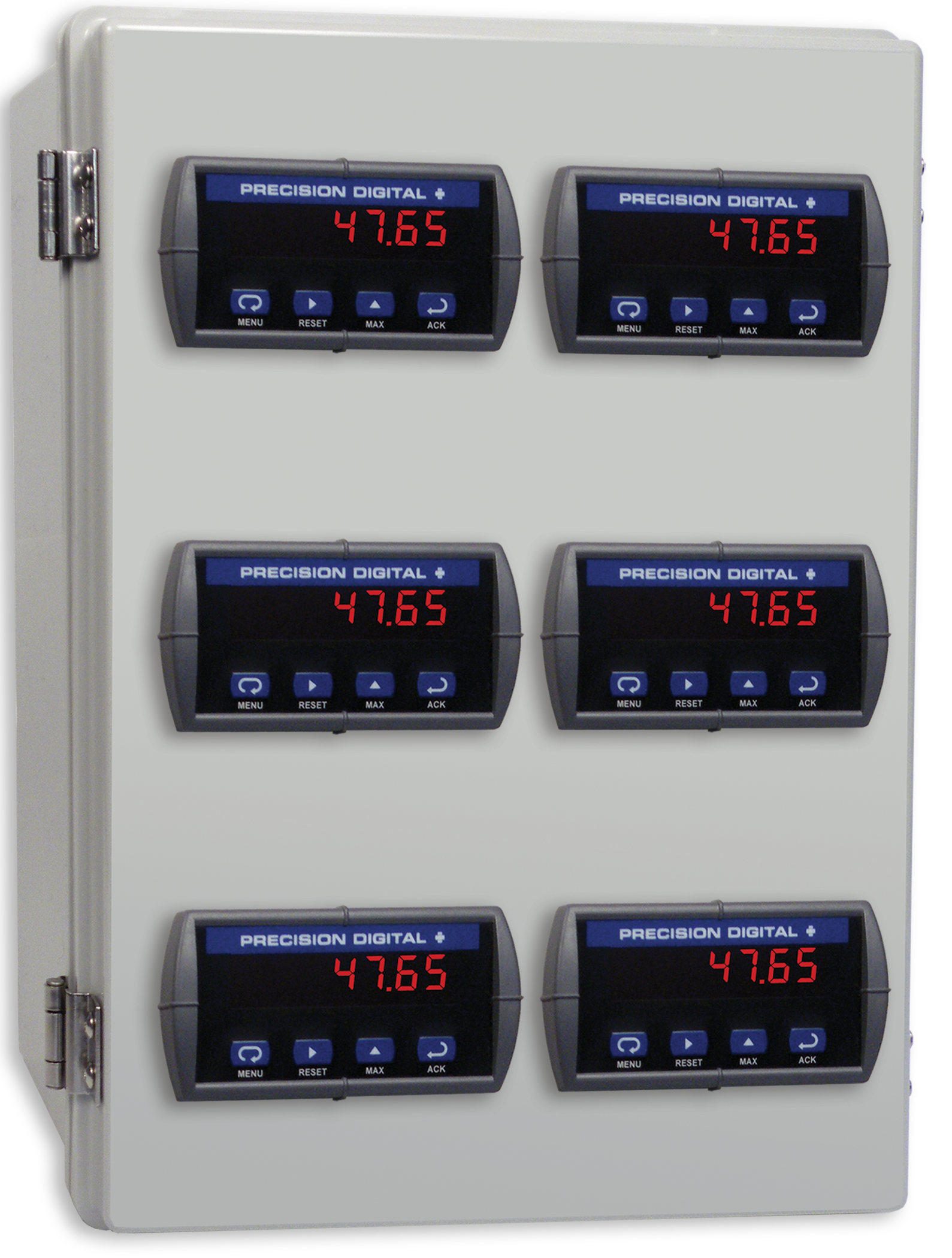
PDA2306
Plastic UL Type 4X Enclosure with (6) Horizontal 1/8 DIN Cutouts
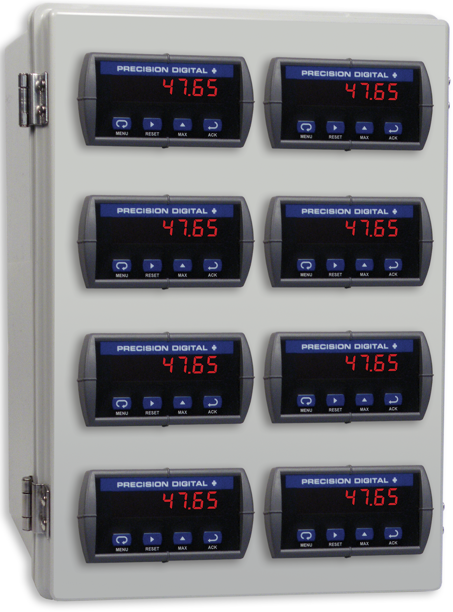
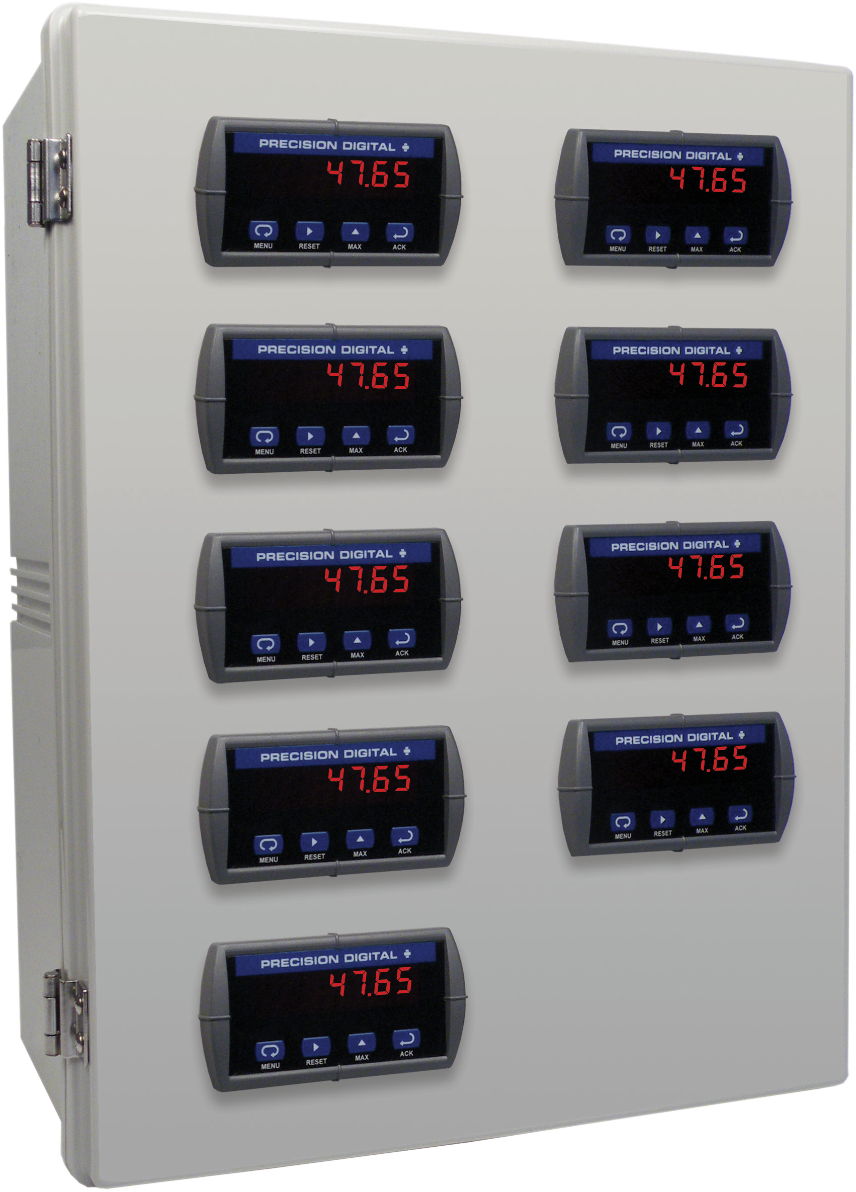
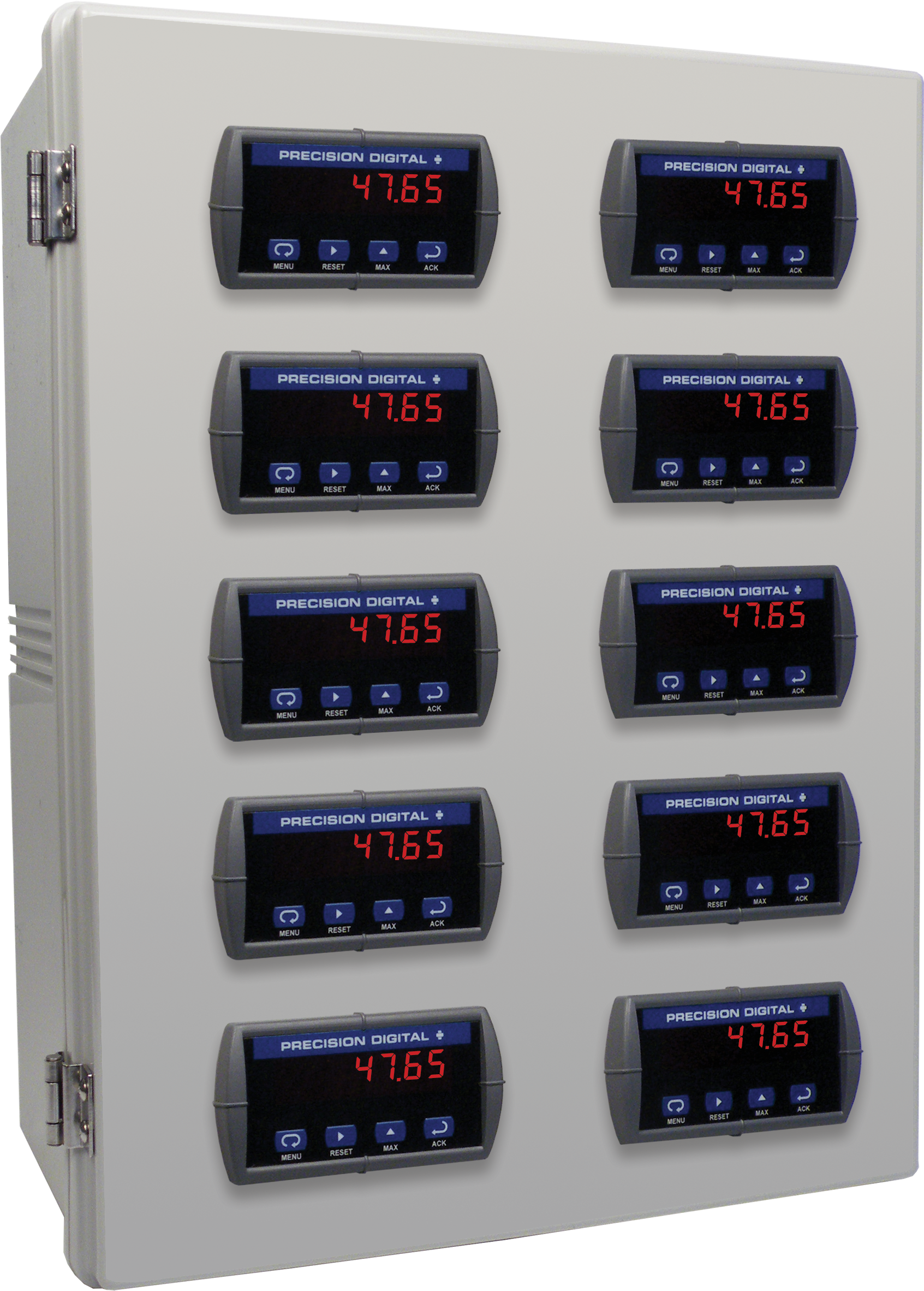
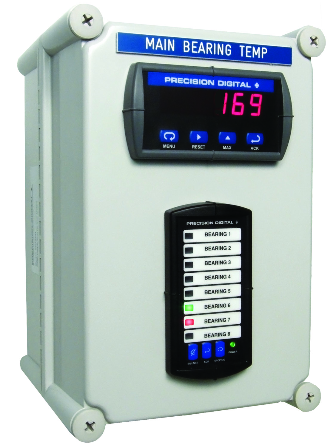
PDA2308
Plastic UL Type 4X Enclosure with (8) Horizontal 1/8 DIN Cutouts
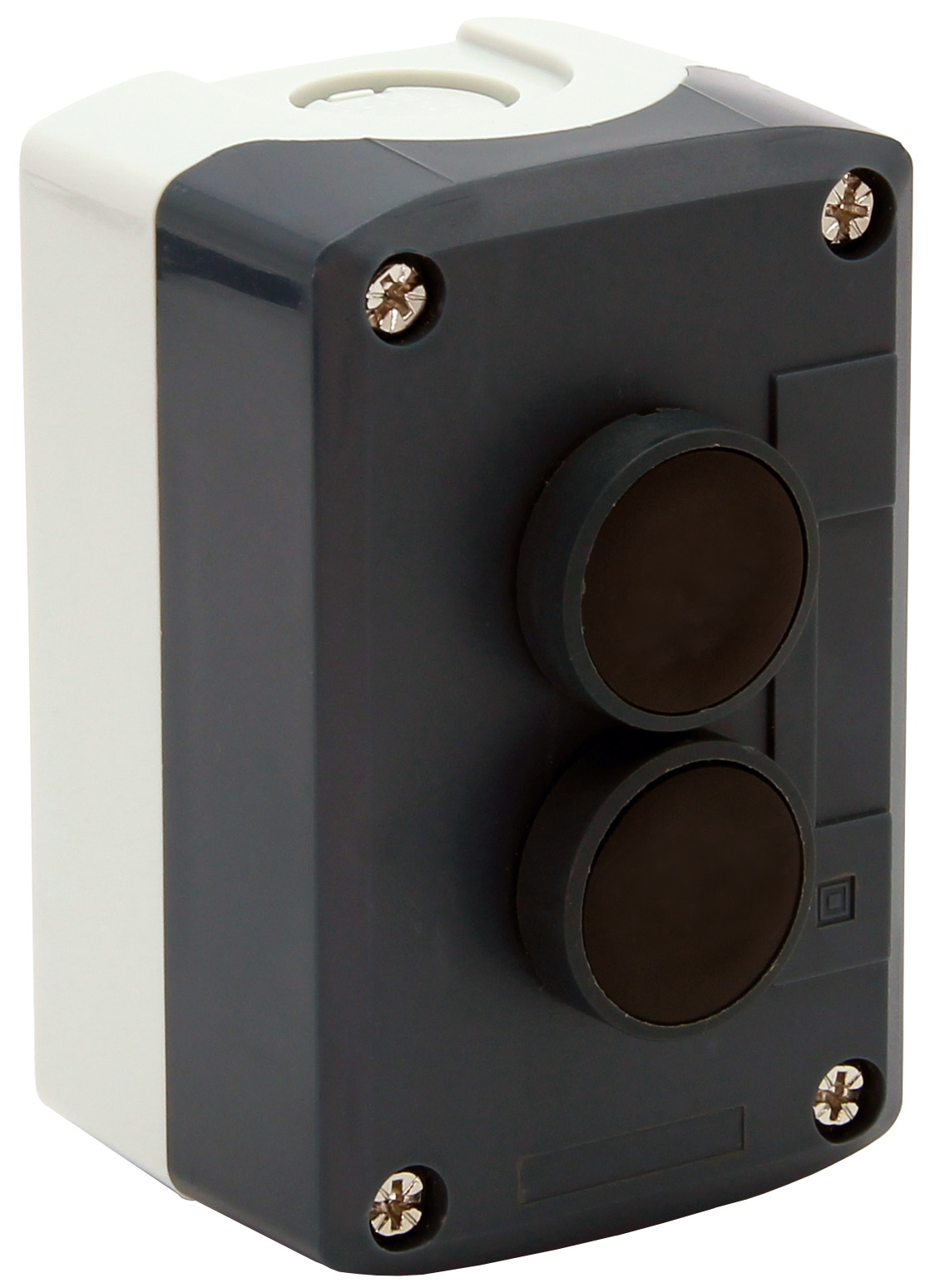
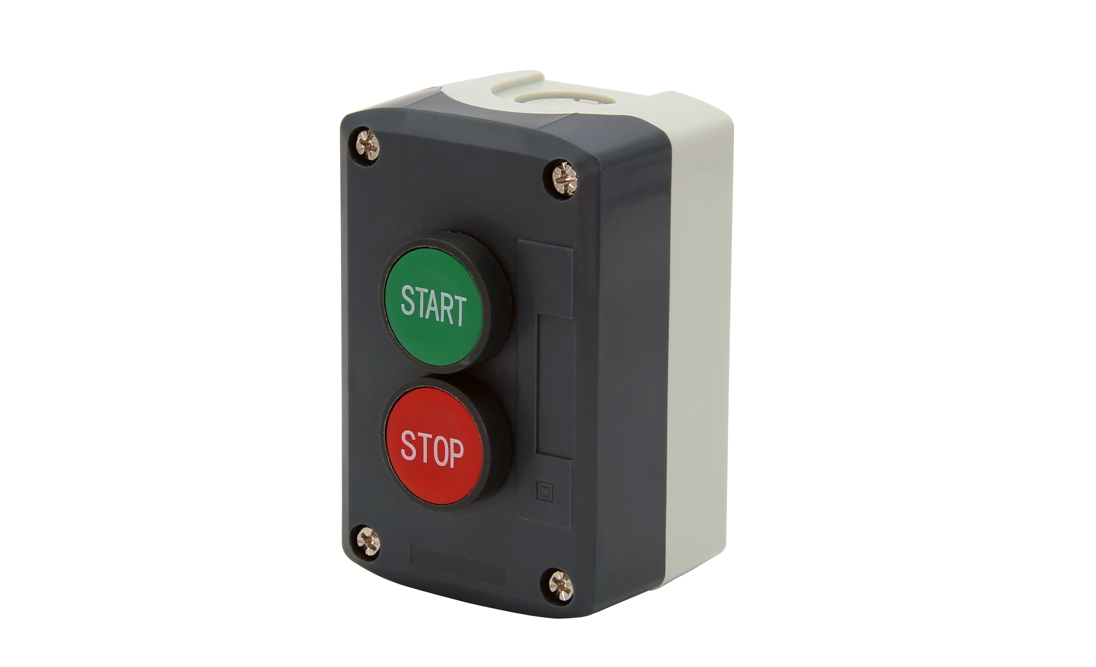
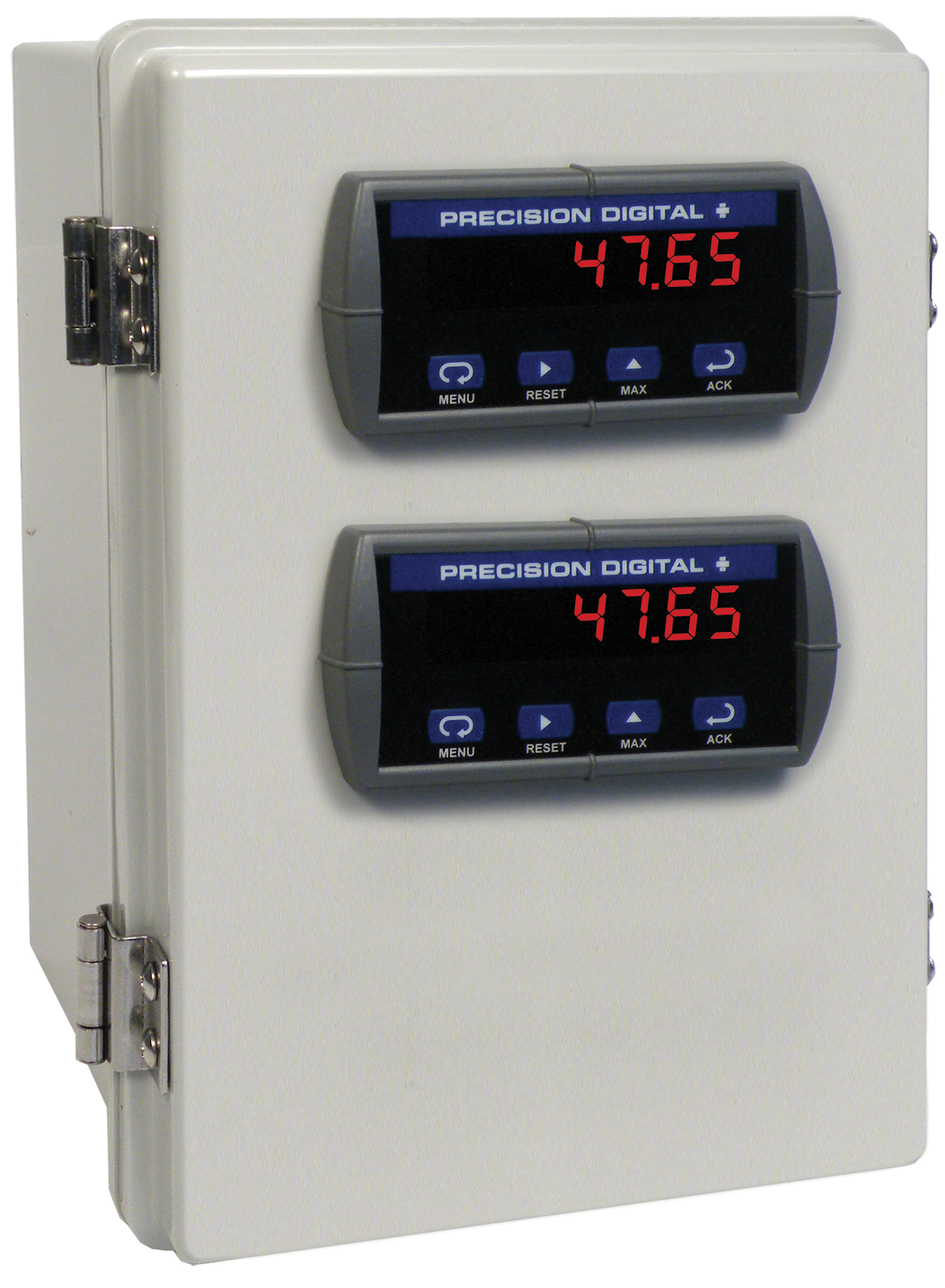
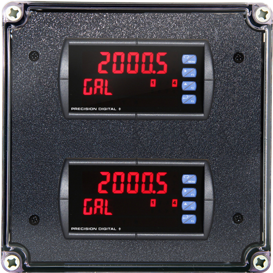
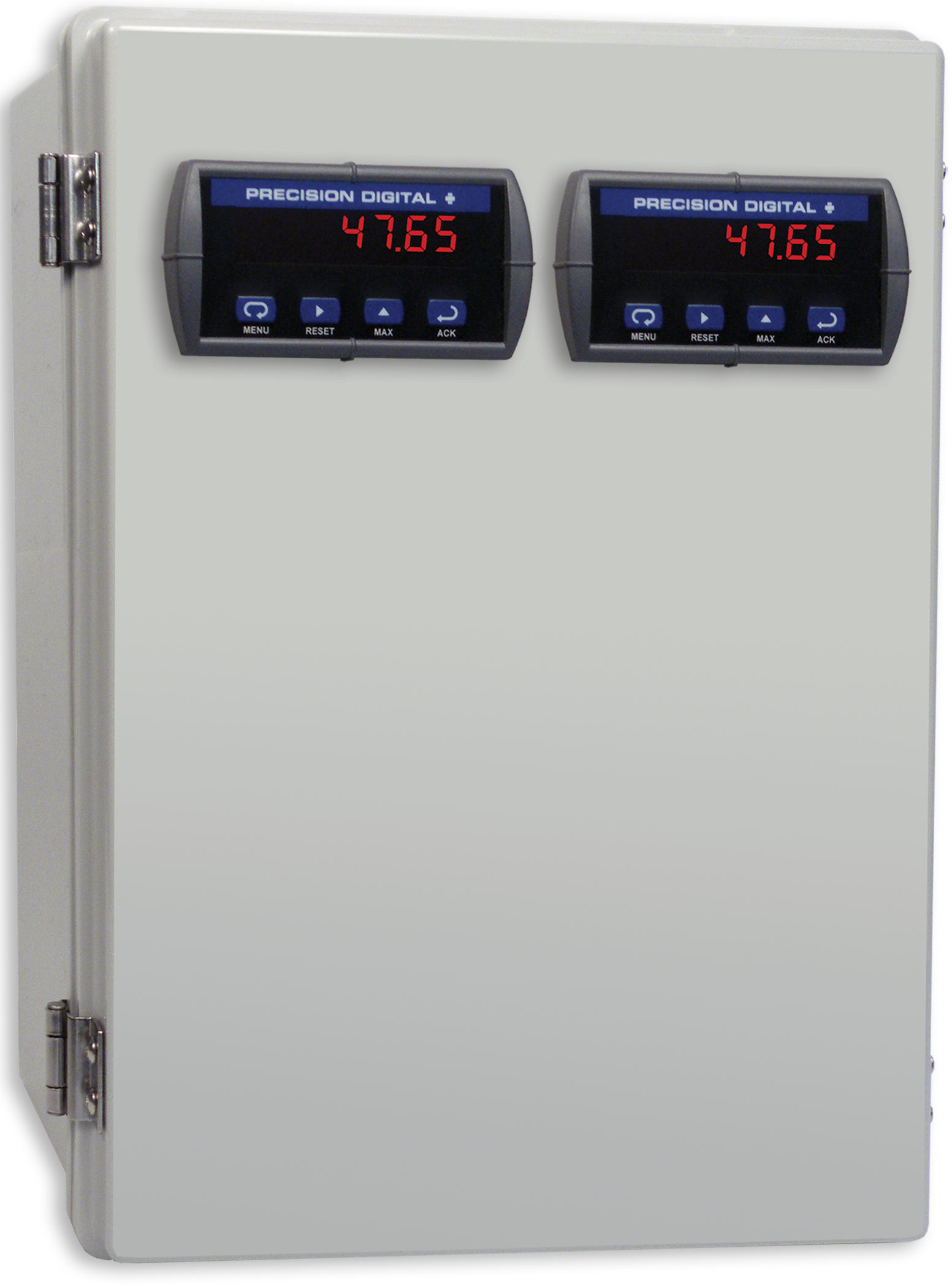
PDA2302
Plastic UL Type 4X Enclosure with (2) Horizontal 1/8 DIN Cutouts
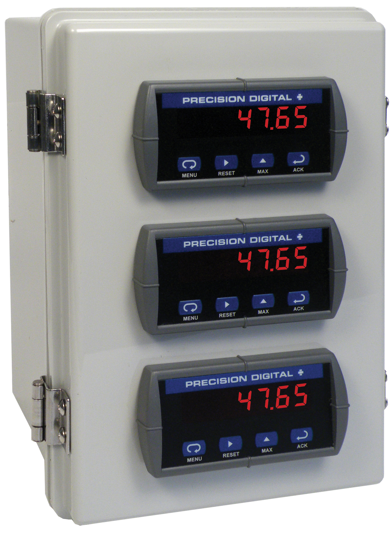
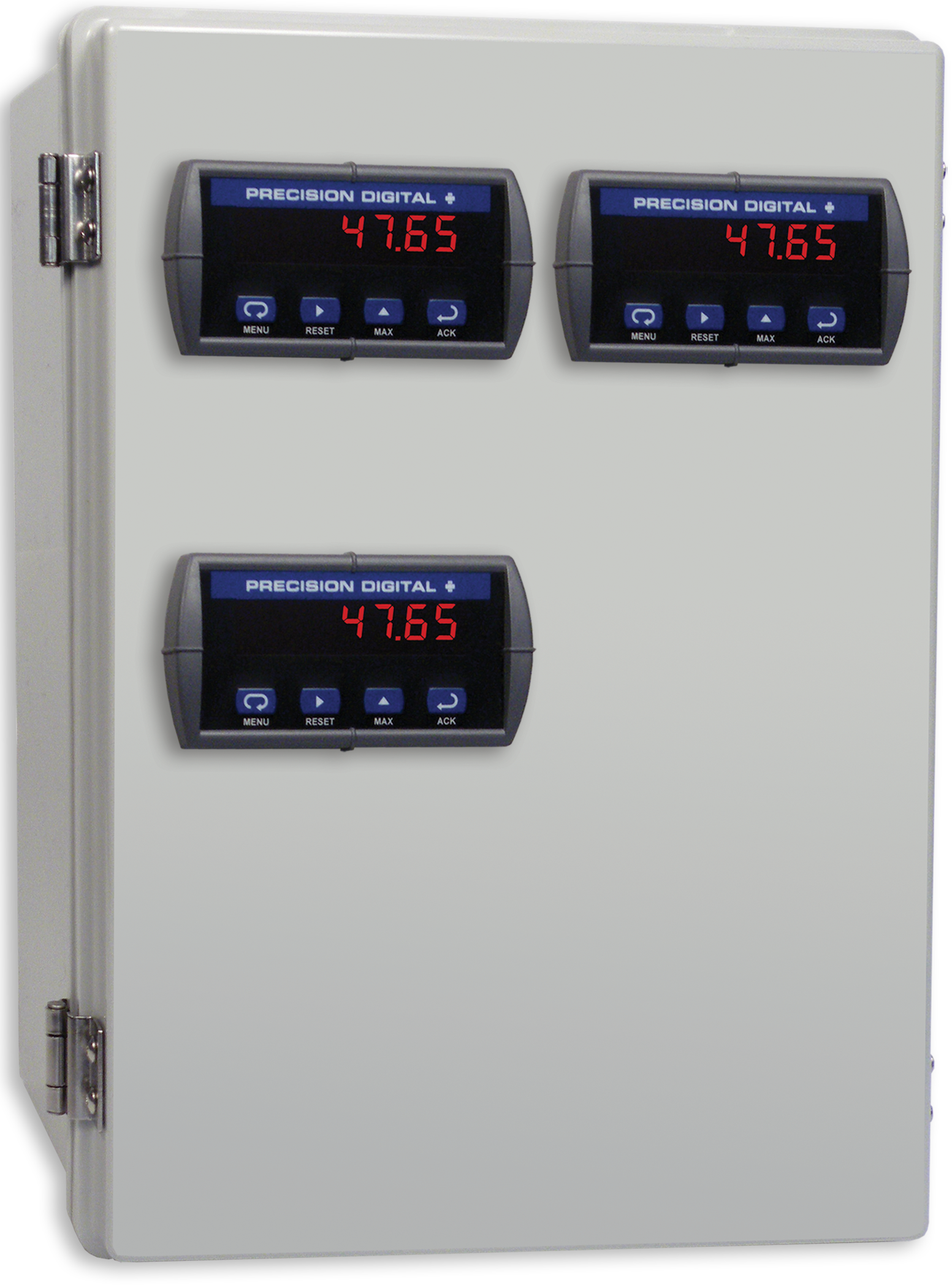
PDA2303
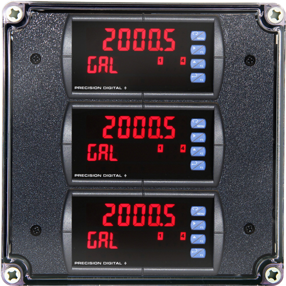
Plastic UL Type 4X Enclosure with (3) Horizontal 1/8 DIN Cutouts
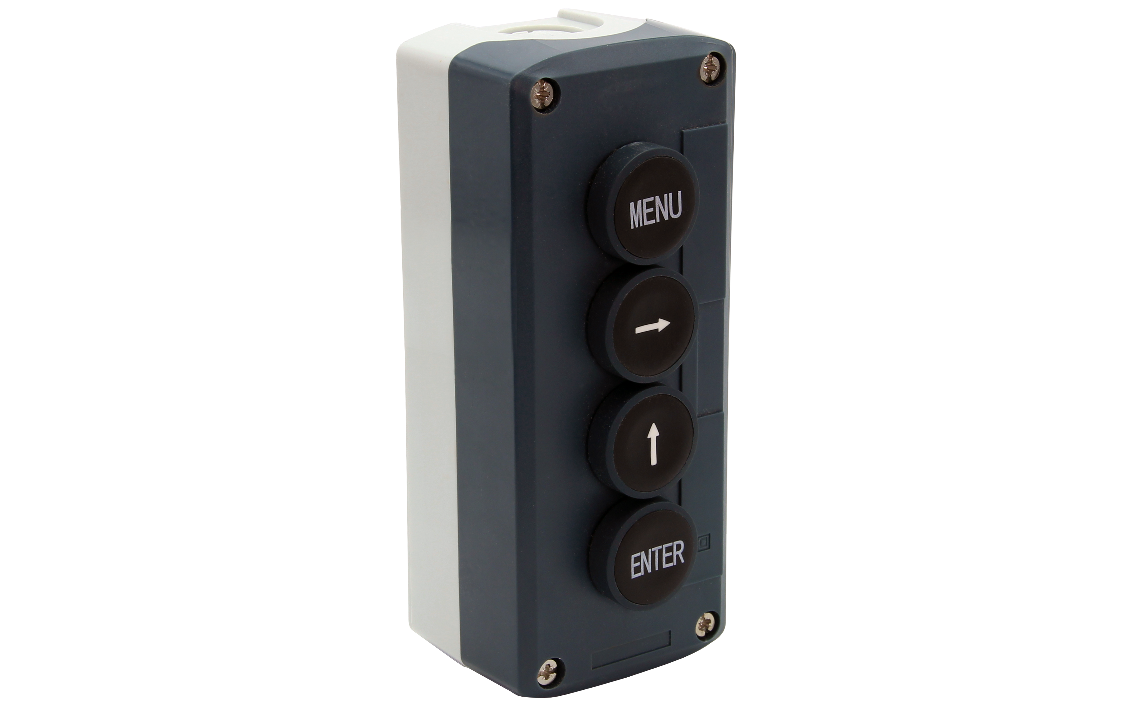
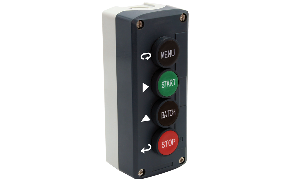
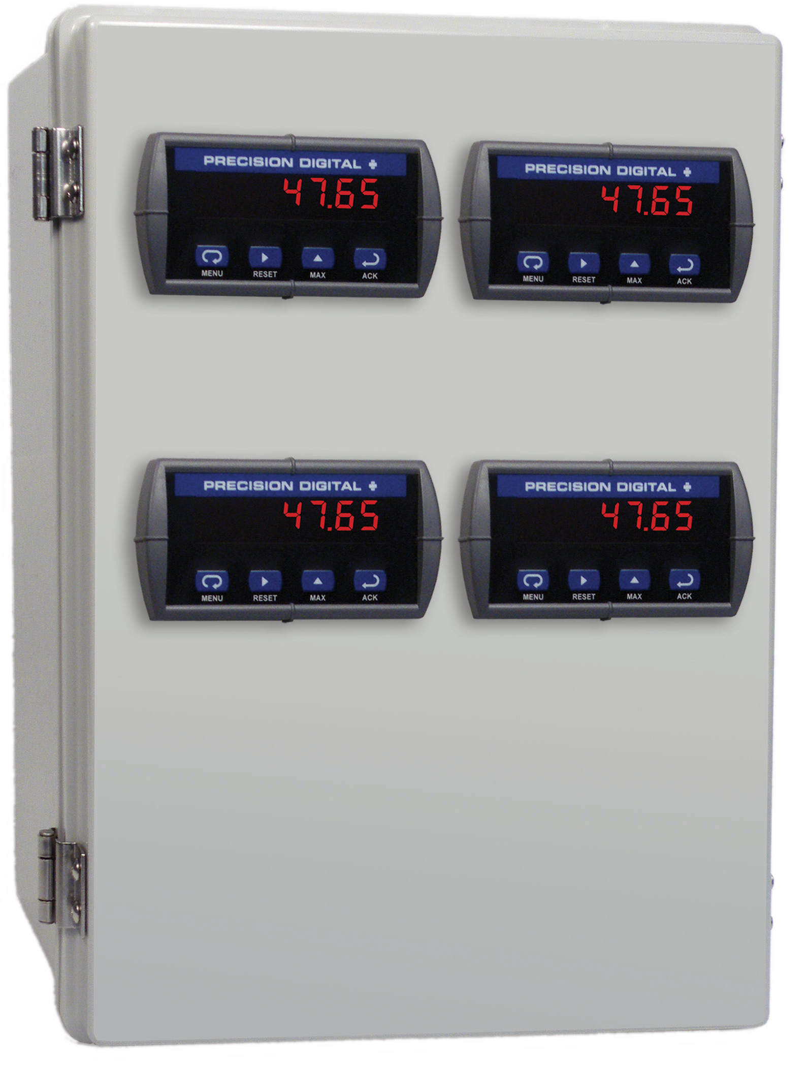
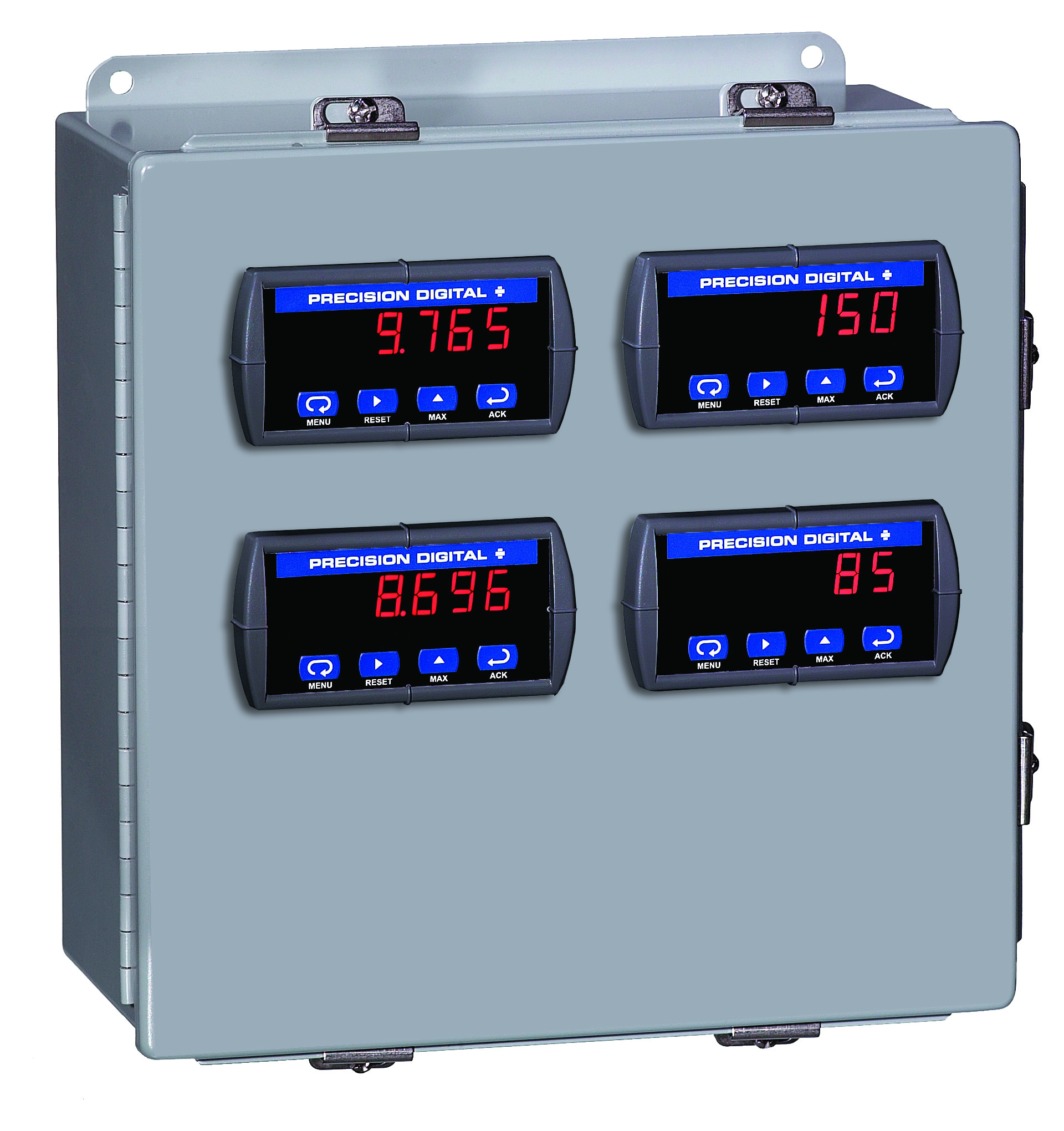
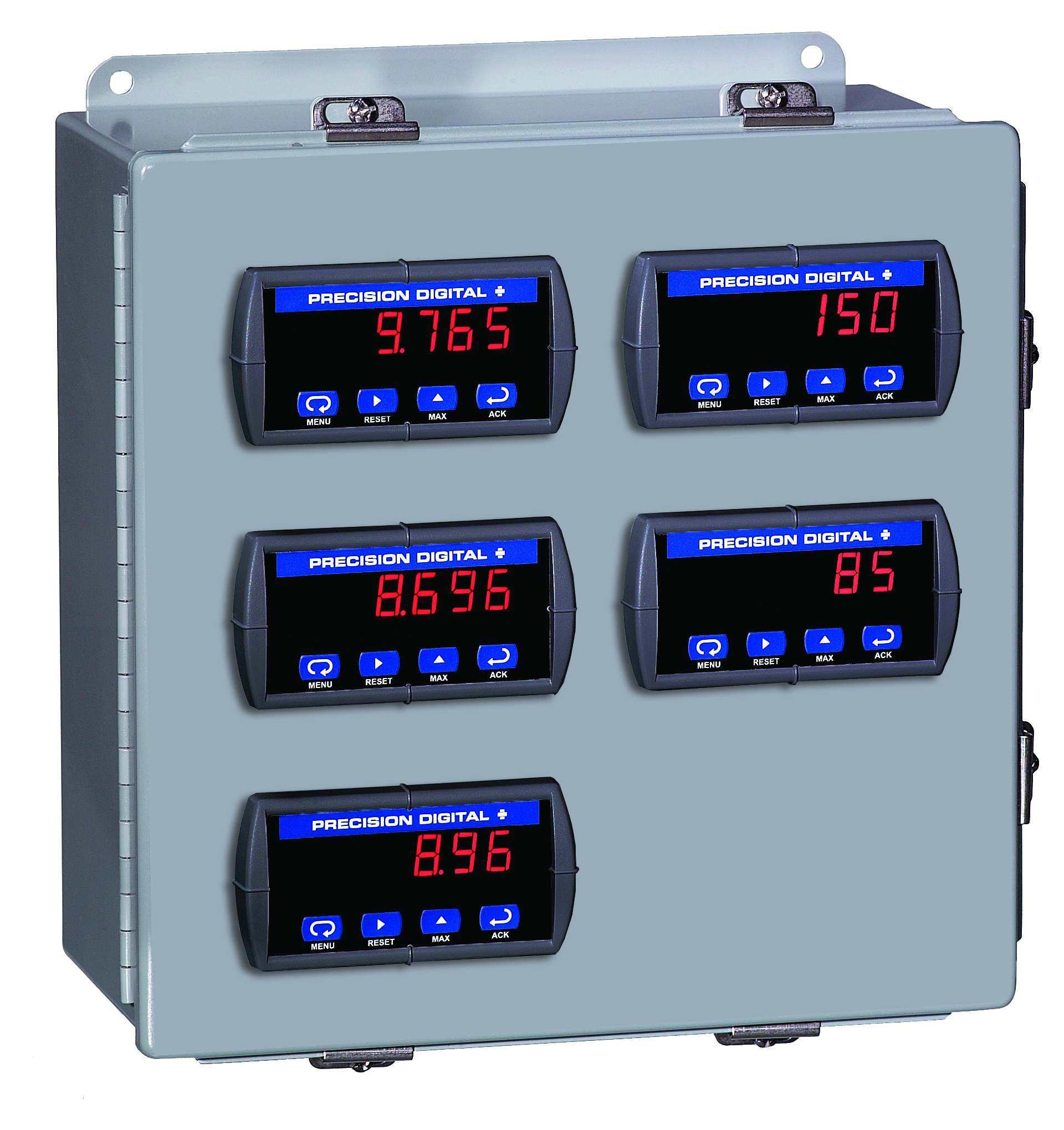
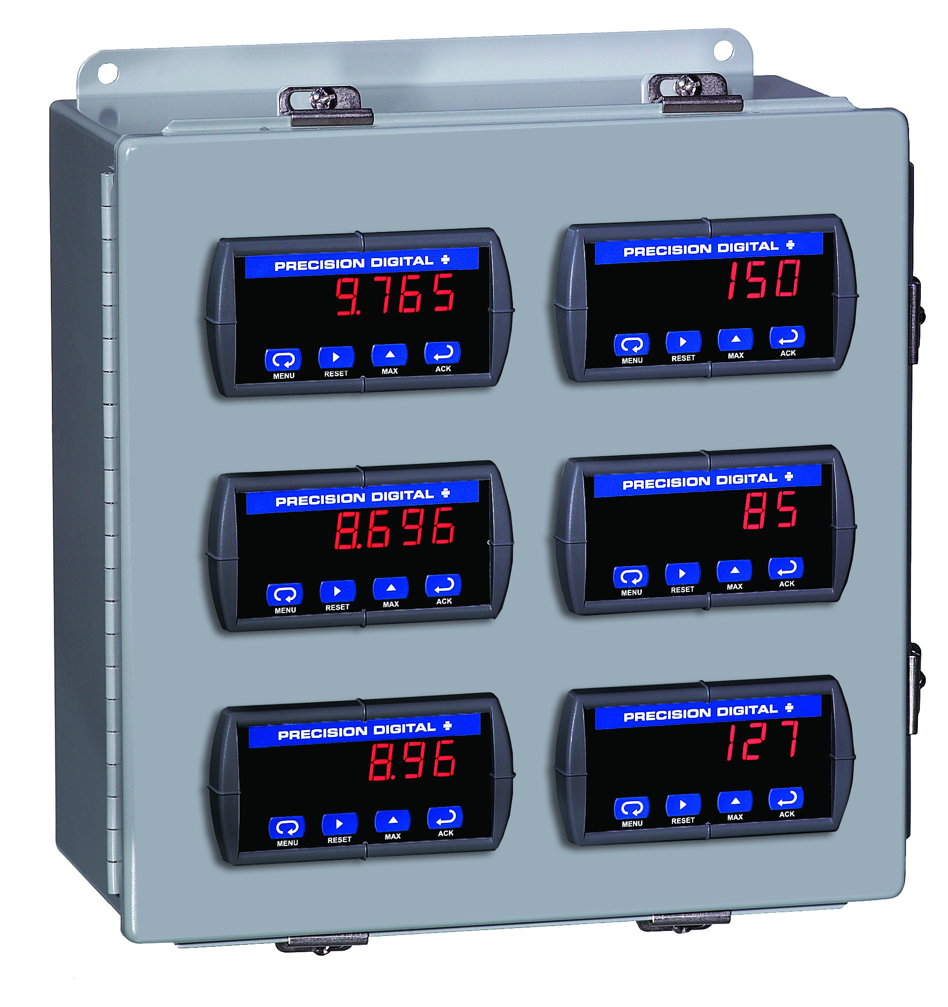
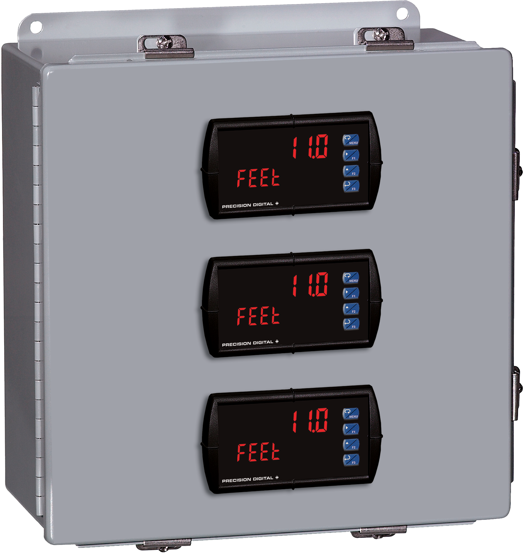
PDA2304
Plastic UL Type 4X Enclosure with (4) Horizontal 1/8 DIN Cutouts
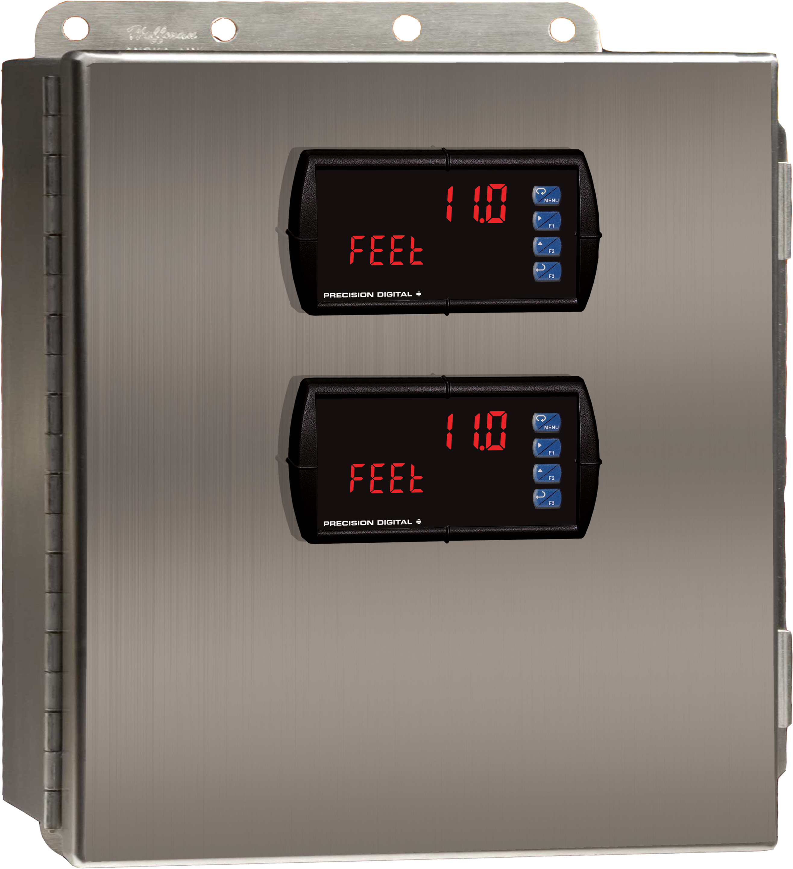
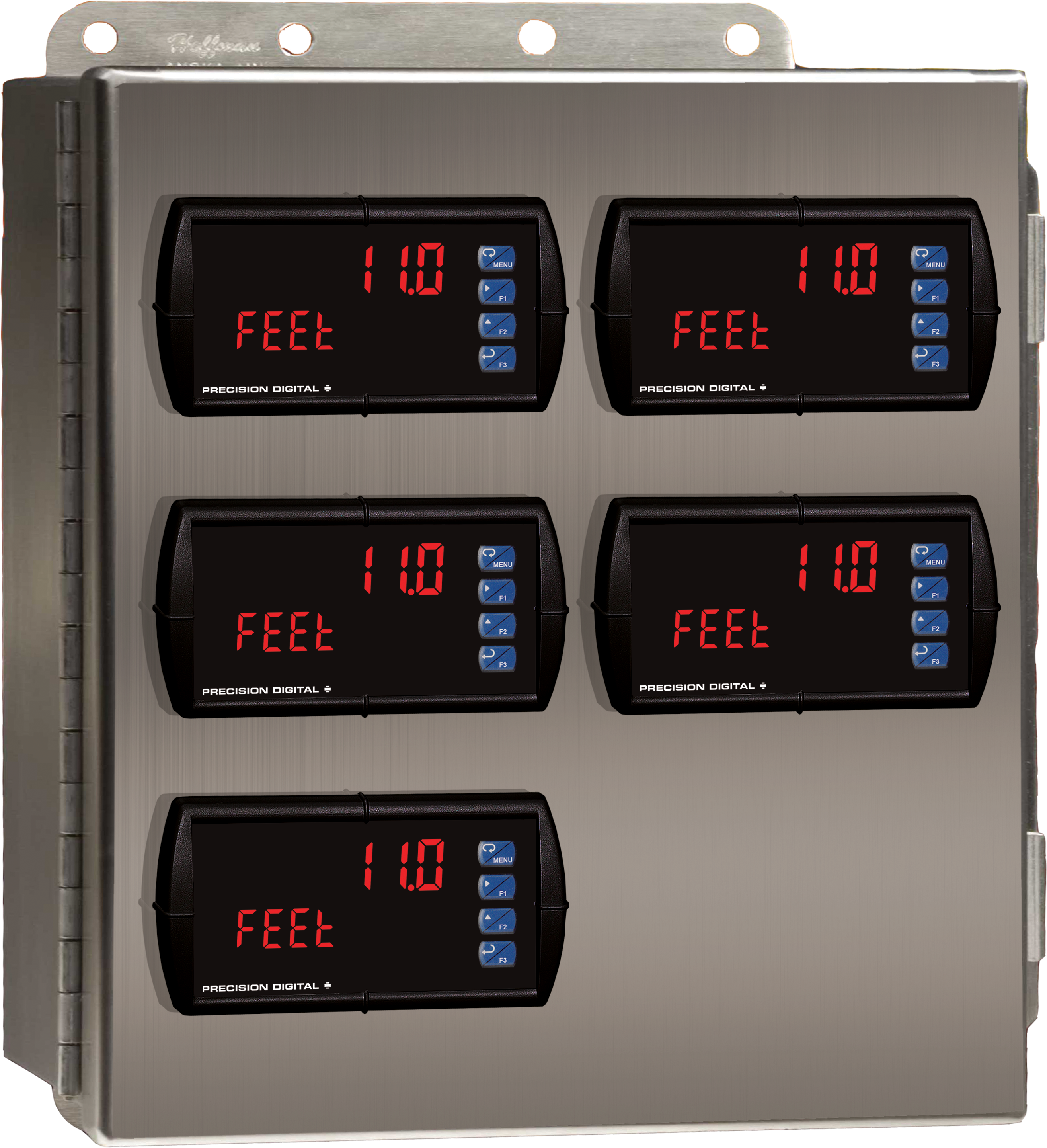
PDA2604
Stainless Steel UL Type 4X Enclosure with (4) Horizontal 1/8 DIN Cutouts
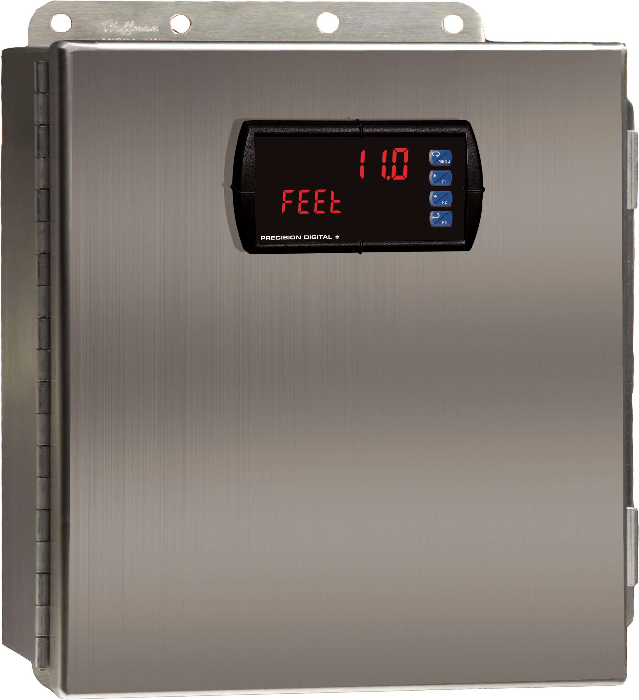
PDA2704
Steel UL Type 4 Enclosure with (4) Horizontal 1/8 DIN Cutouts
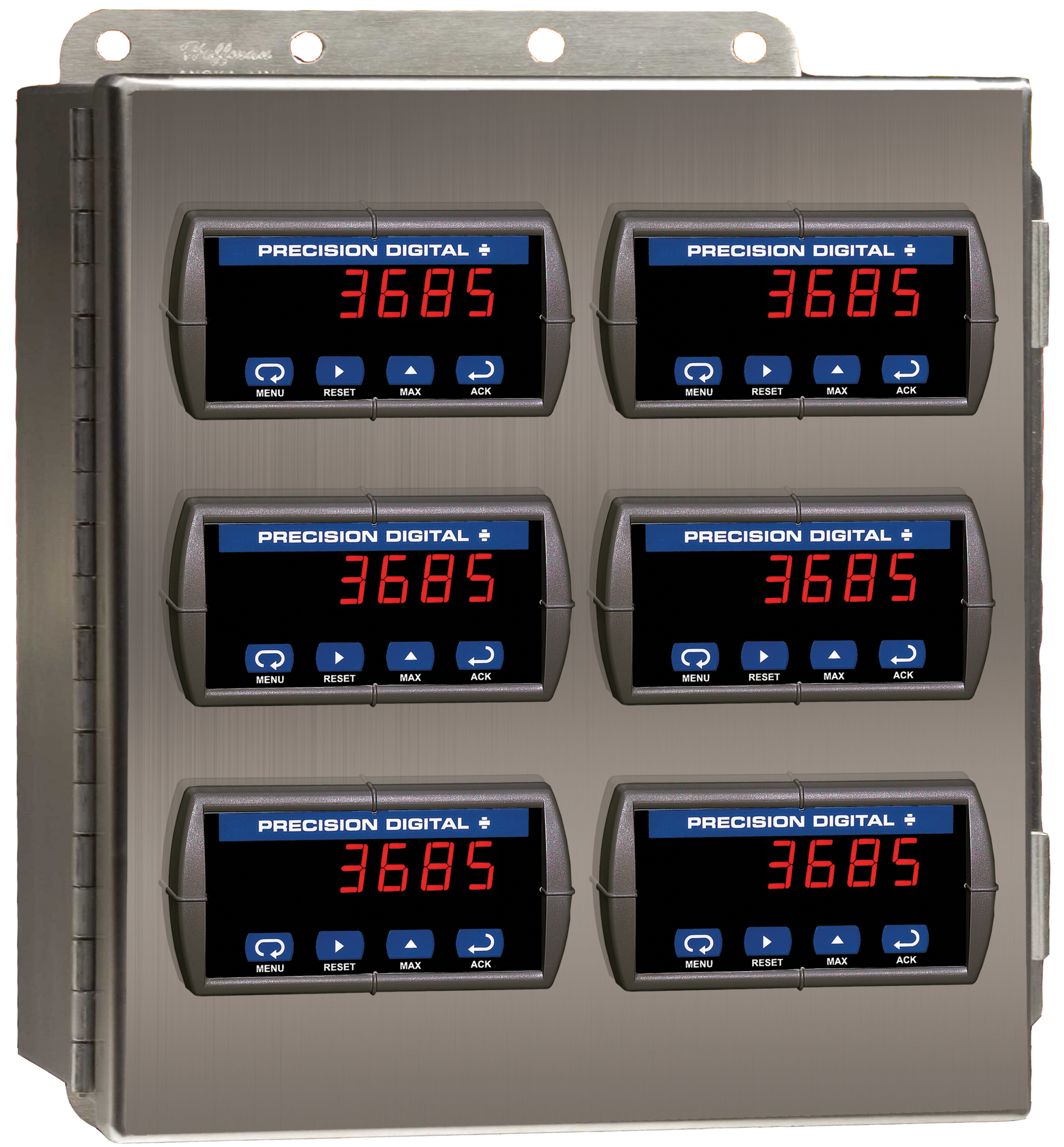
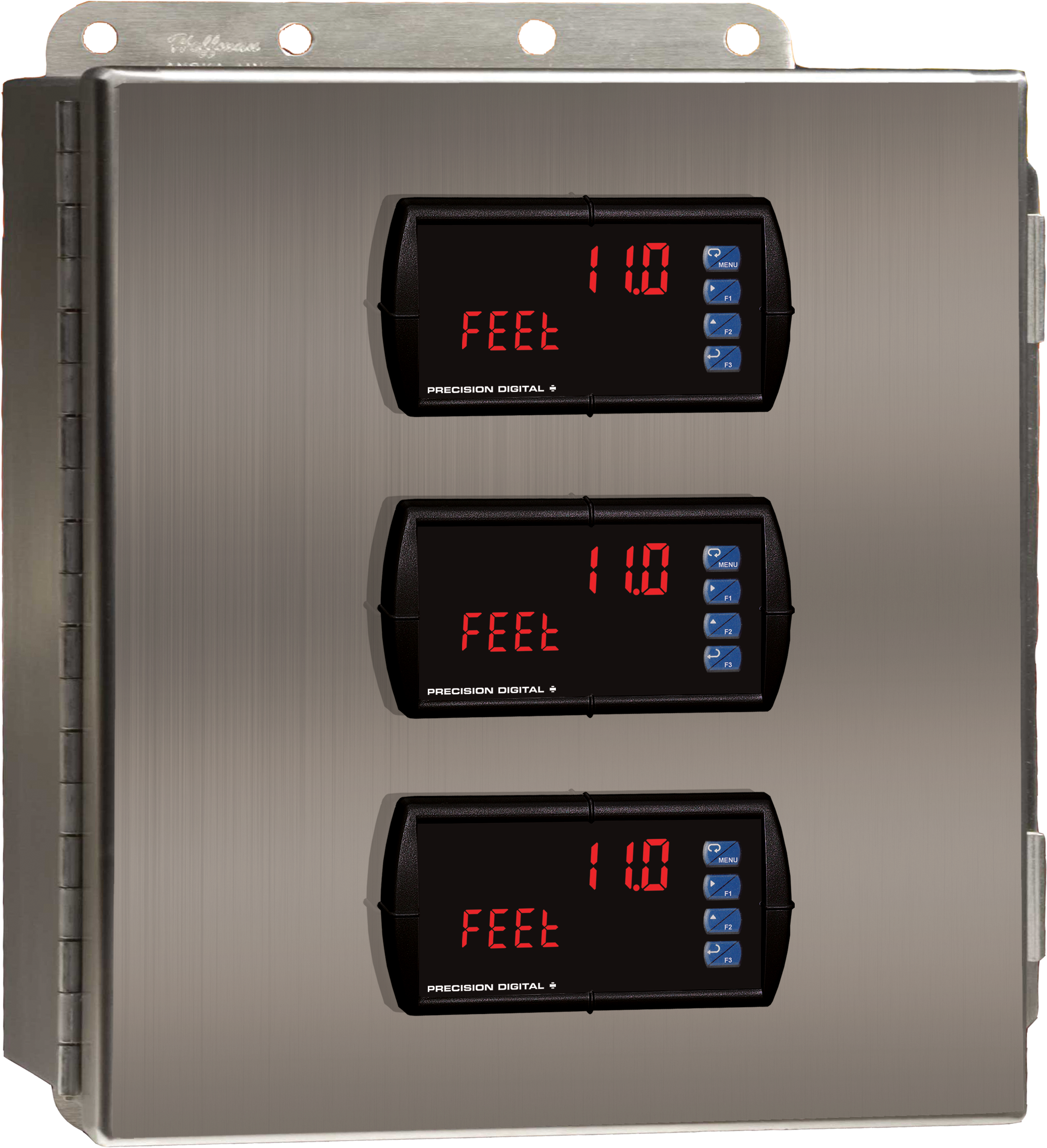
PDA2606
Stainless Steel UL Type 4X Enclosure with (6) Horizontal 1/8 DIN Cutouts
PDA2811
Plastic UL Type 4X Enclosure with (1) Horizontal 1/8 DIN Cutout
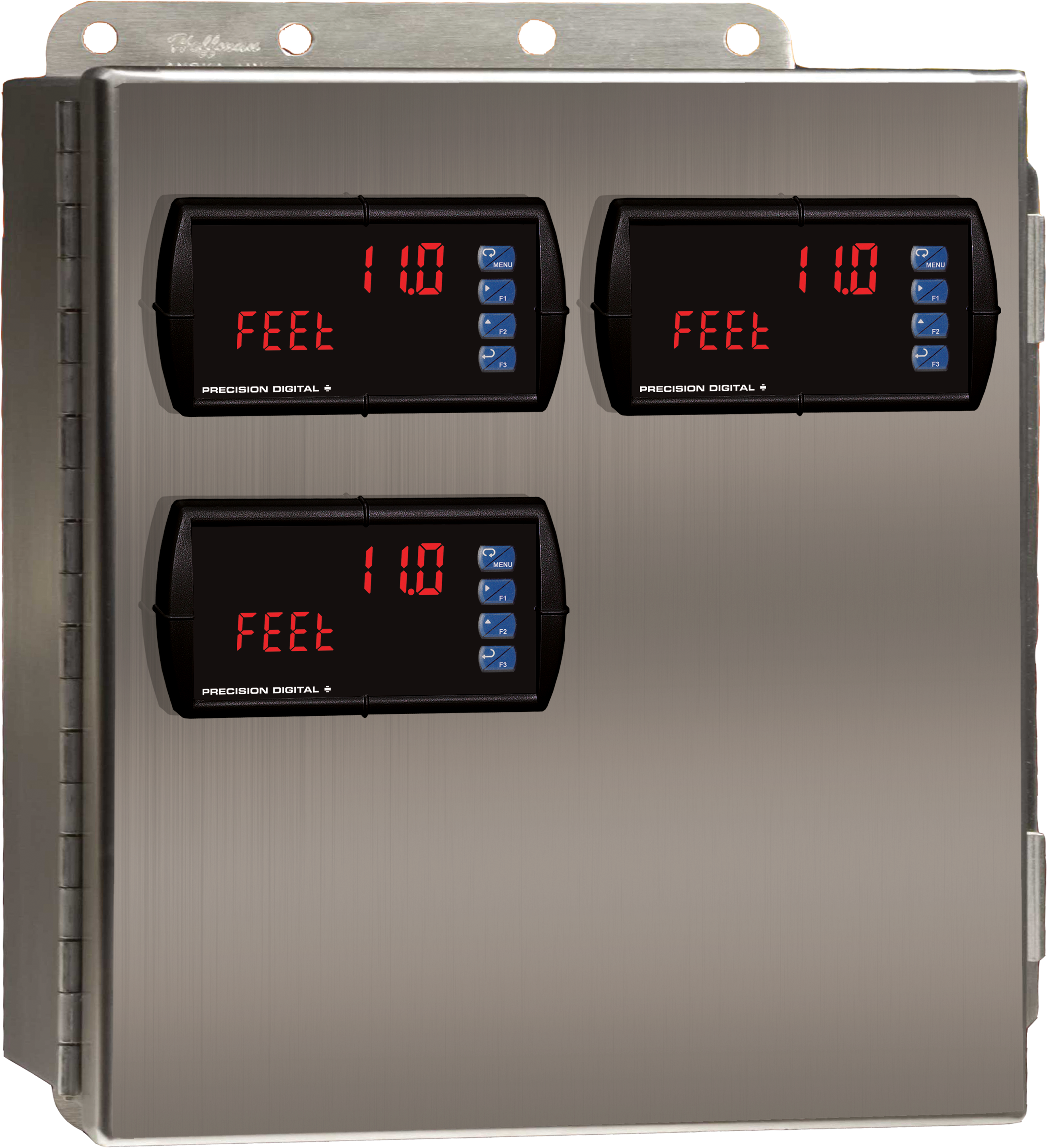
PDA2604-3
Stainless Steel UL Type 4X Enclosure with (3) Horizontal 1/8 DIN Cutouts
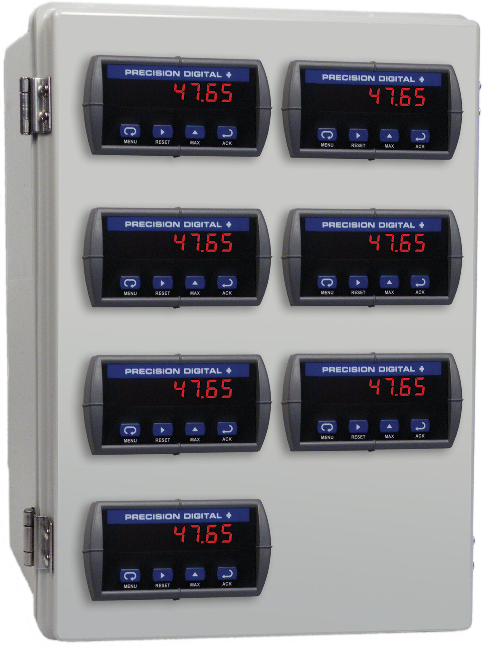
PDA2307
Plastic UL Type 4X Enclosure with (7) Horizontal 1/8 DIN Cutouts
PDA2309
Plastic UL Type 4X Enclosure with (9) Horizontal 1/8 DIN Cutouts
PDA2310
Plastic UL Type 4X Enclosure with (10) Horizontal 1/8 DIN Cutouts
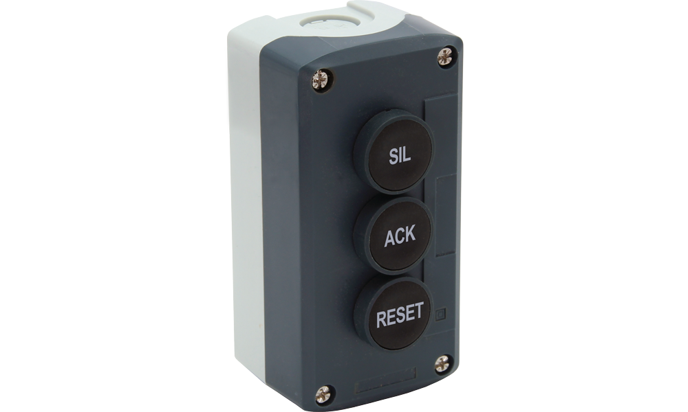
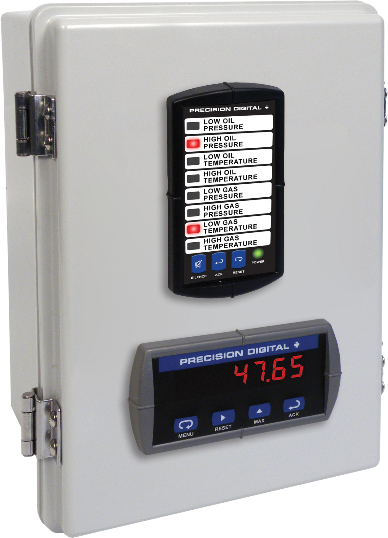
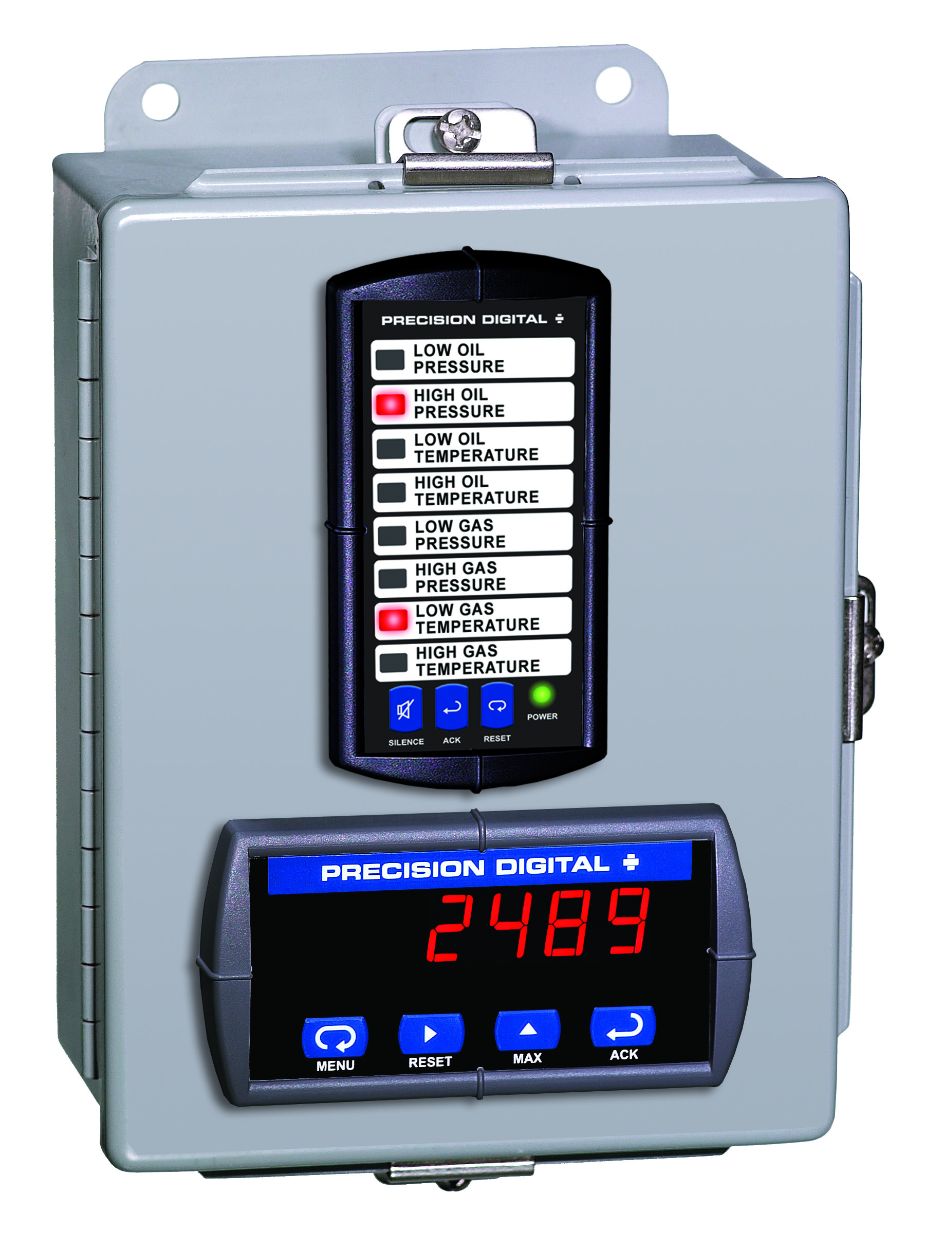
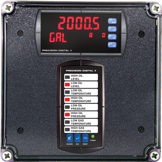
PDA2322
Plastic UL Type 4X Enclosure with (1) Vertical and (1) Horizontal 1/8 DIN Cutouts
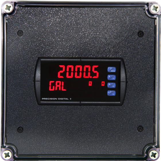
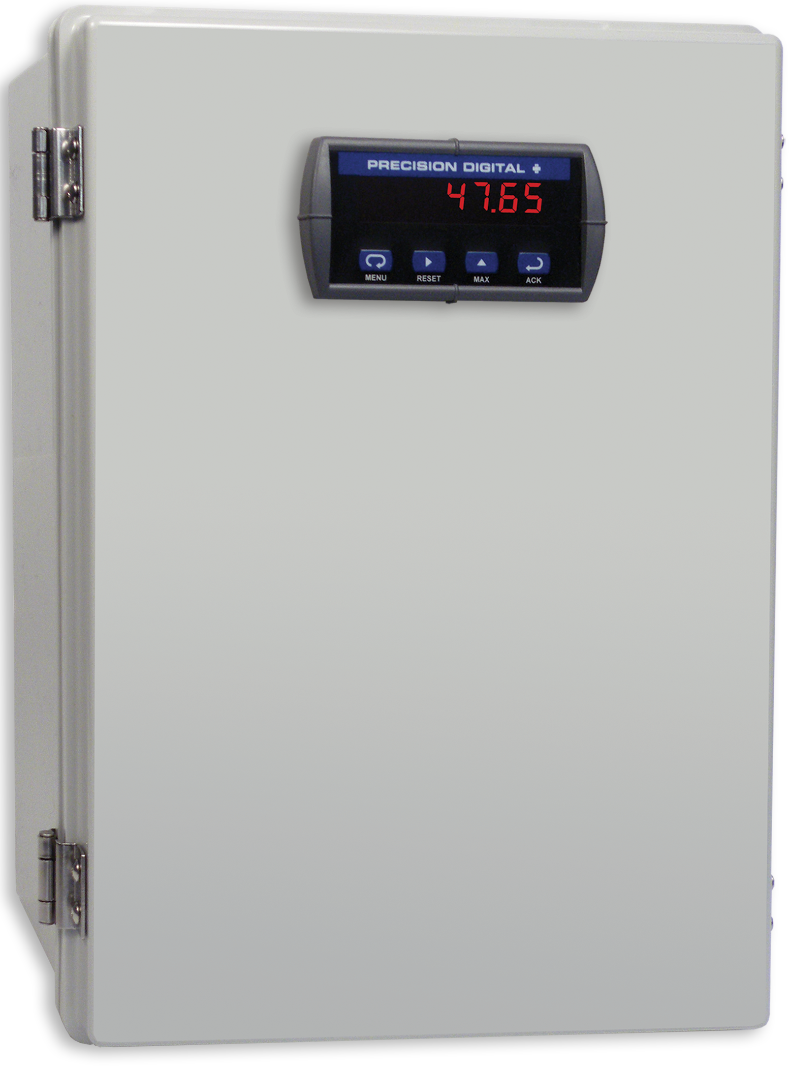
PDA2301
Plastic UL Type 4X Enclosure with (1) Horizontal 1/8 DIN Cutout
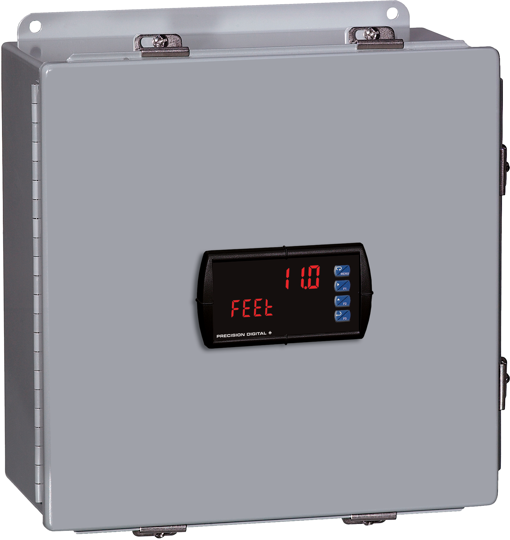
PDA2704-1
Steel UL Type 4 Enclosure with (1) Horizontal 1/8 DIN Cutout
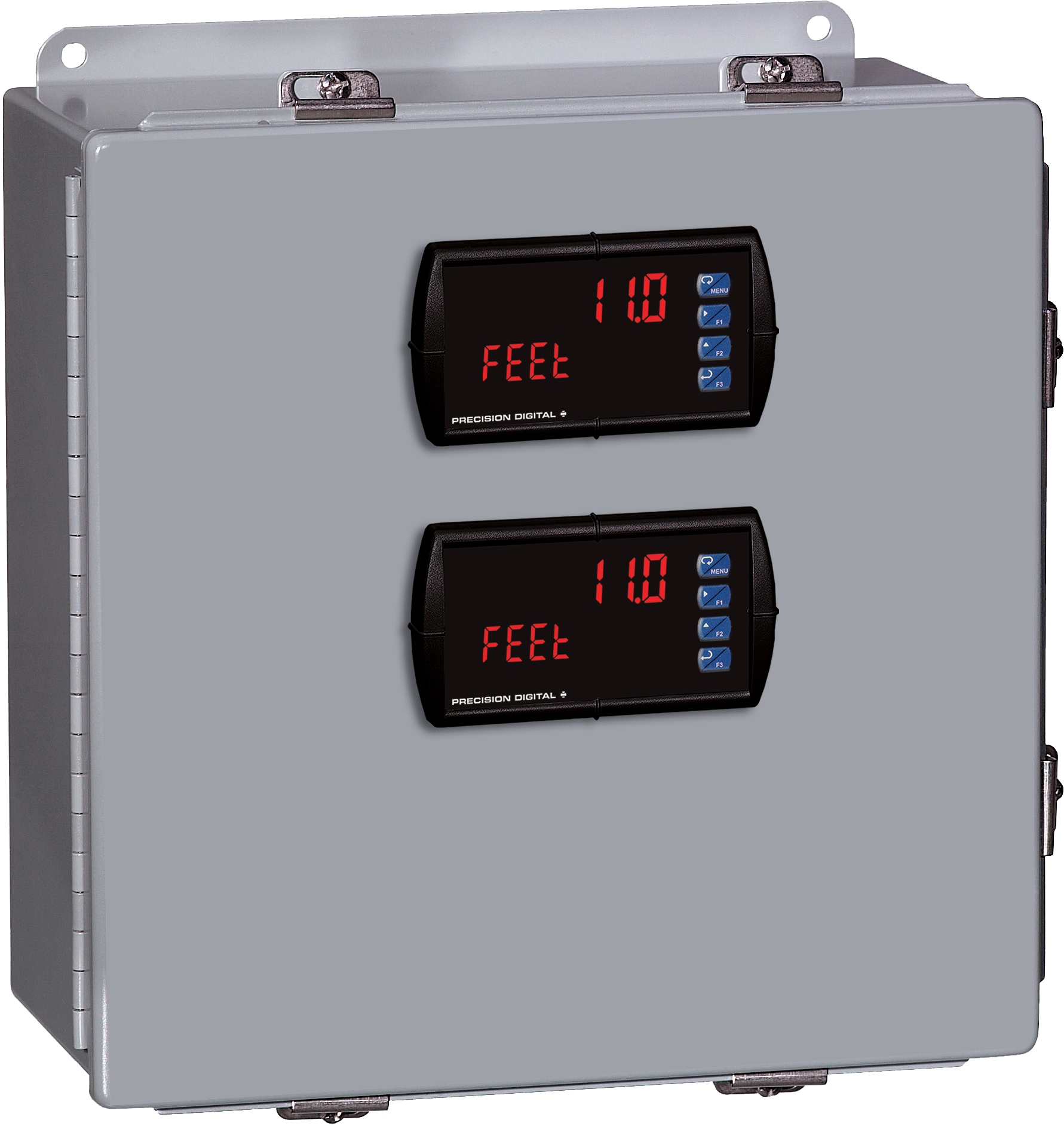
PDA2704-2
Steel UL Type 4 Enclosure with (2) Horizontal 1/8 DIN Cutouts
PDA2705
Steel UL Type 4 Enclosure with (5) Horizontal 1/8 DIN Cutouts
PDA2706
Steel UL Type 4 Enclosure with (6) Horizontal 1/8 DIN Cutouts
PDA2722
Steel UL Type 4 Enclosure with (1) Vertical and (1) Horizontal 1/8 DIN Cutouts
PDA3412
Plastic UL Type 4X Enclosure with (3) Horizontal 1/8 DIN Cutouts
PDA3414
Plastic UL Type 4X Enclosure with (1) Vertical and (1) Horizontal 1/8 DIN Cutouts
PDA2812
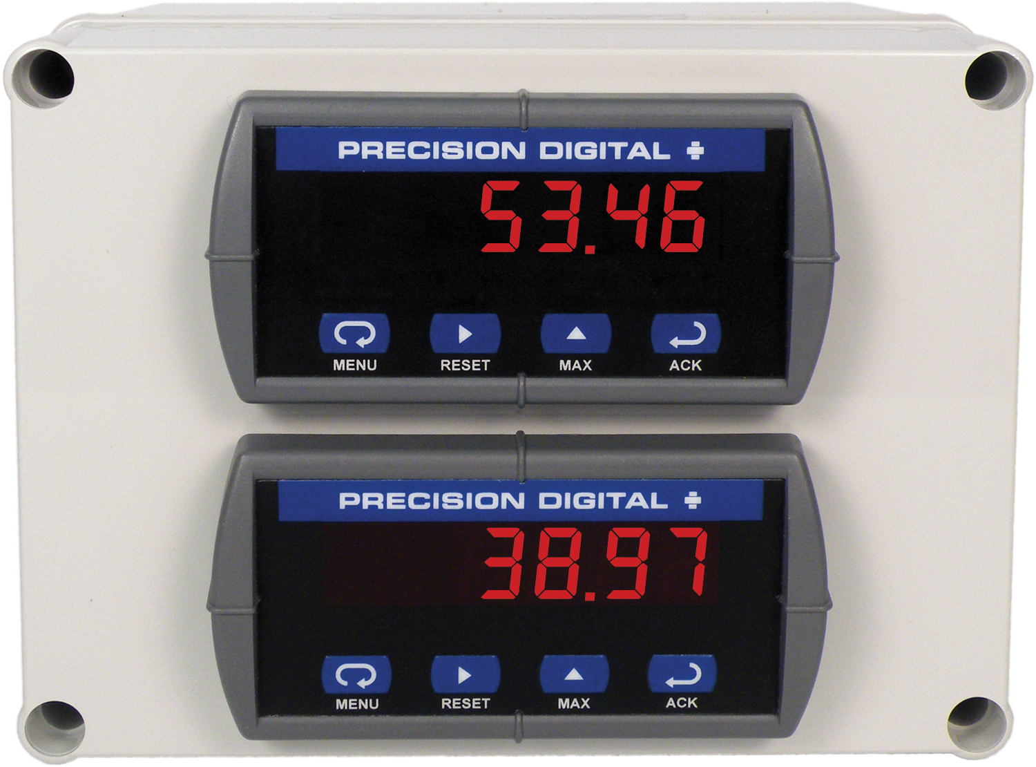
Plastic UL Type 4X Enclosure with (2) Horizontal 1/8 DIN Cutouts
PDA2821
Plastic UL Type 4X Enclosure with (1) Vertical and (1) Horizontal 1/8 DIN Cutouts
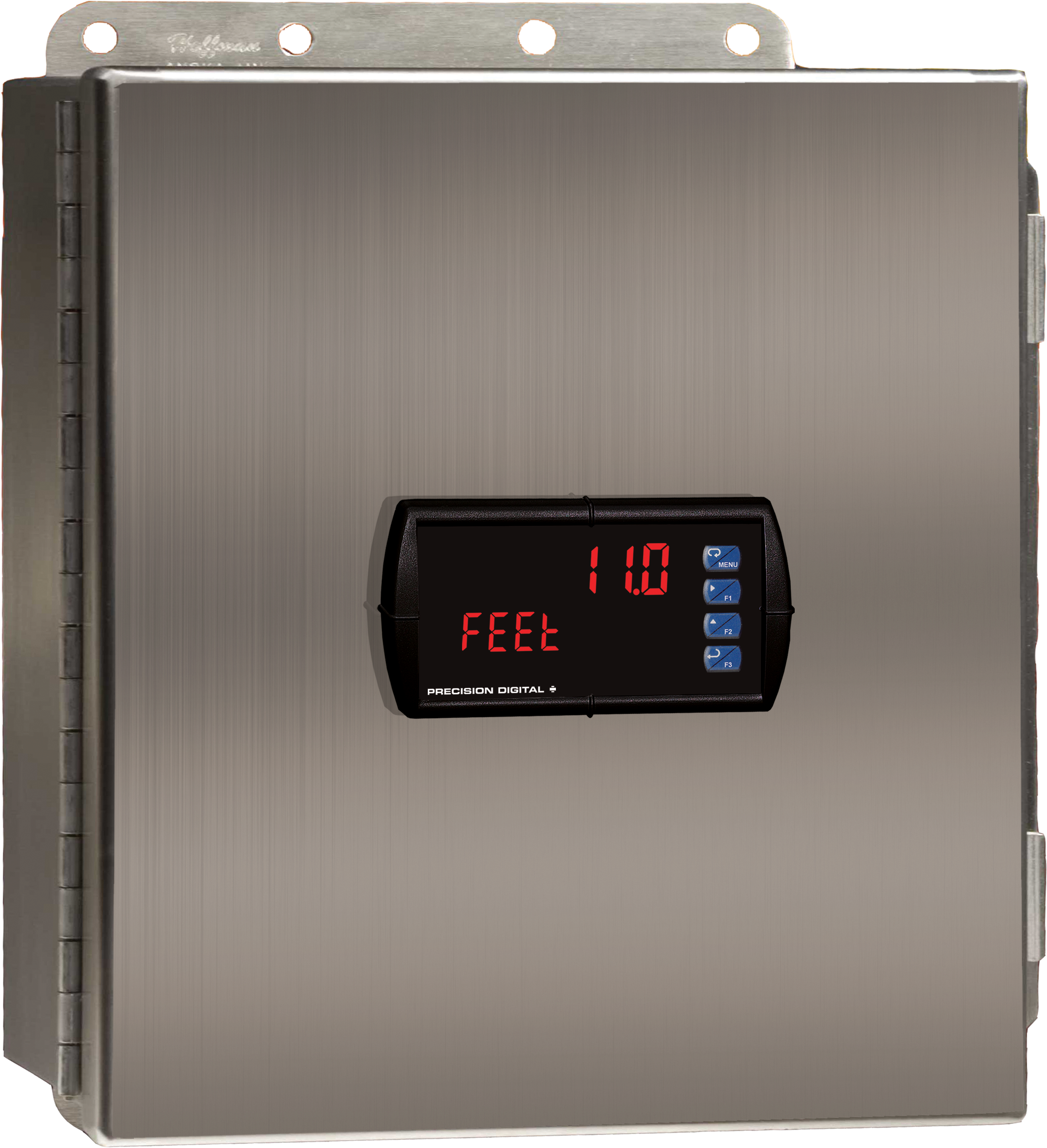
PDA3407
Plastic UL Type 4X Enclosure with (1) Horizontal 1/8 DIN Cutout
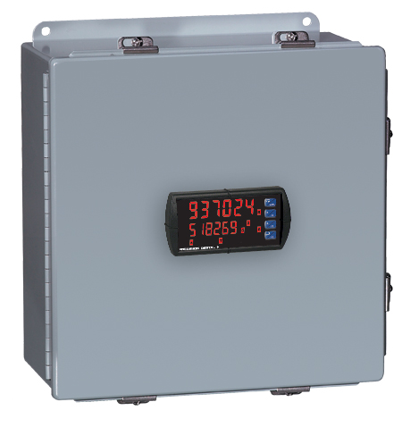
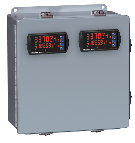
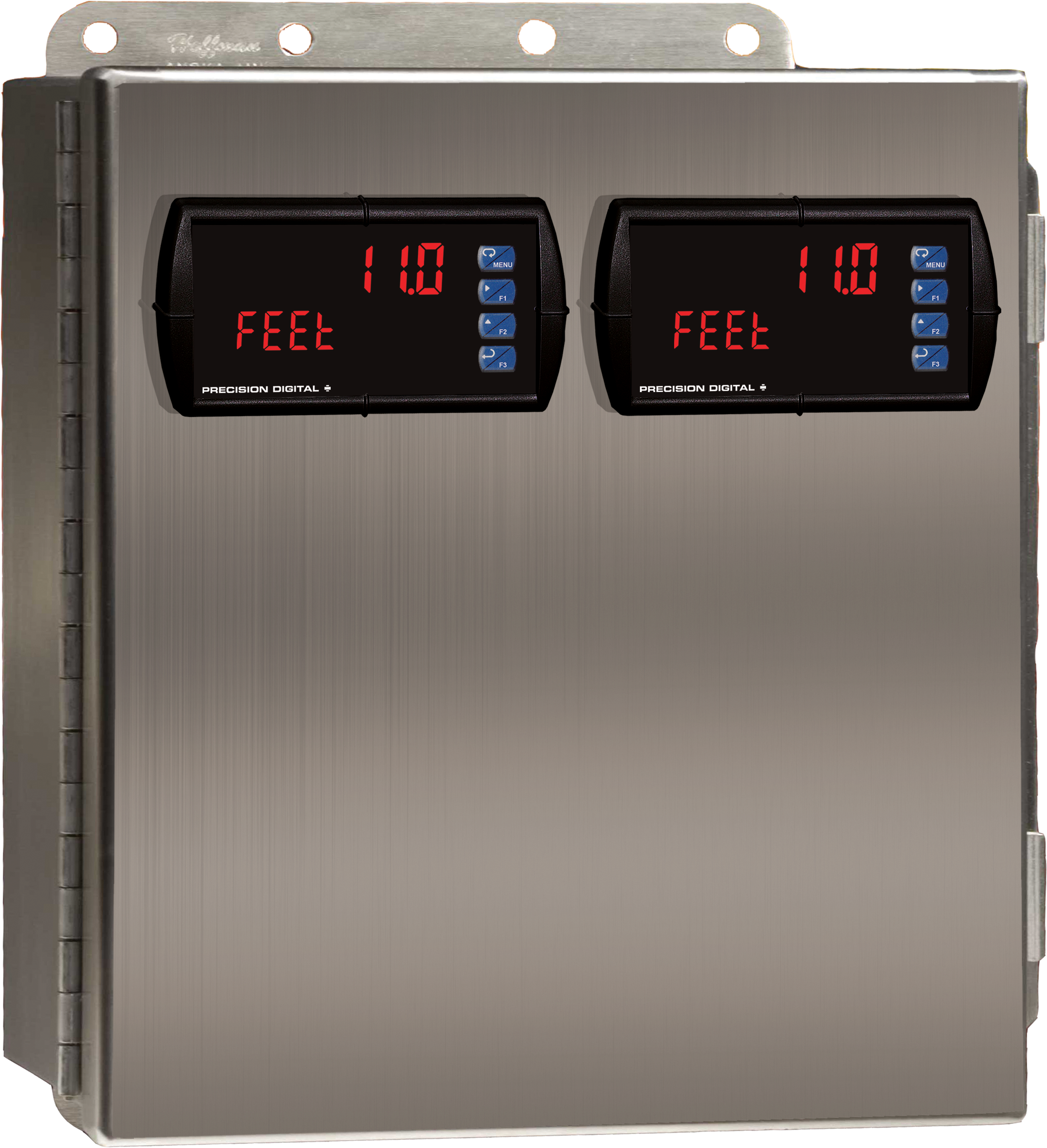
PDA3411
Plastic UL Type 4X Enclosure with (2) Horizontal 1/8 DIN Cutouts
PDA2604-1
Stainless Steel UL Type 4X Enclosure with (1) Horizontal 1/8 DIN Cutout
PDA2704-3
Steel UL Type 4 Enclosure with (3) Horizontal 1/8 DIN Cutouts
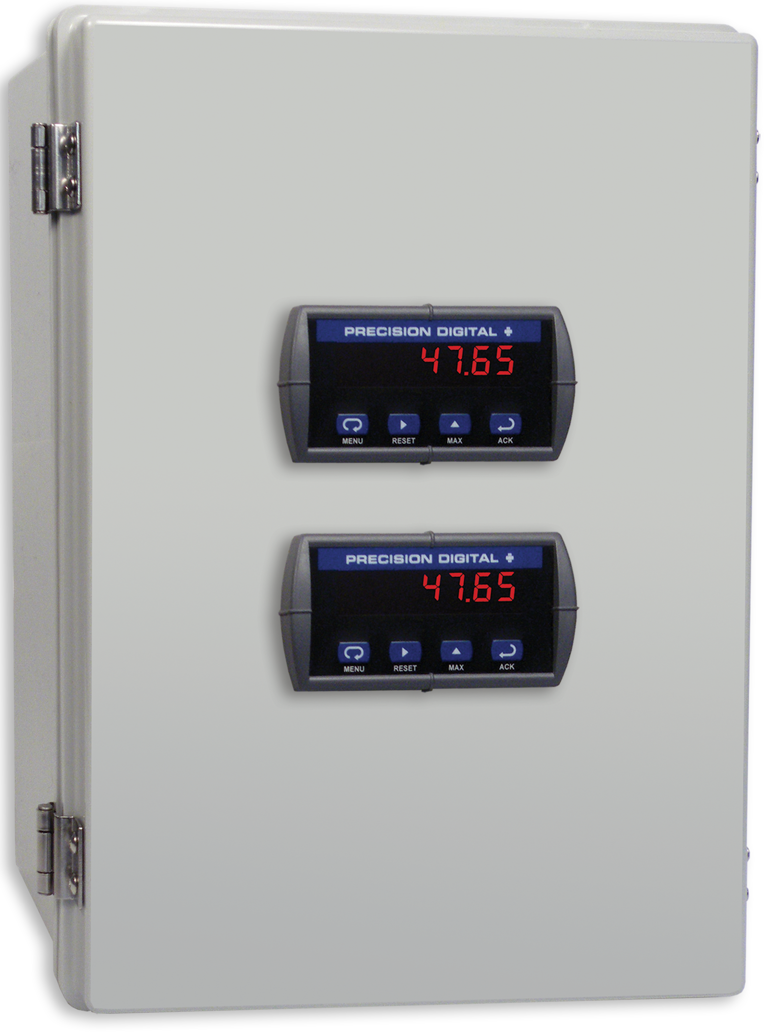
PDA2304-1
Plastic UL Type 4X Enclosure with (1) Horizontal 1/8 DIN Cutout
PDA2304-2
Plastic UL Type 4X Enclosure with (2) Horizontal 1/8 DIN Cutouts
PDA2304-3
Plastic UL Type 4X Enclosure with (3) Horizontal 1/8 DIN Cutouts
PDA2312
Plastic UL Type 4X Enclosure with (2) Horizontal 1/8 DIN Cutouts
PDA2603-1
Stainless Steel UL Type 4X Enclosure with (1) Horizontal 1/8 DIN Cutout
PDA2603-2
Stainless Steel UL Type 4X Enclosure with (2) Horizontal 1/8 DIN Cutouts
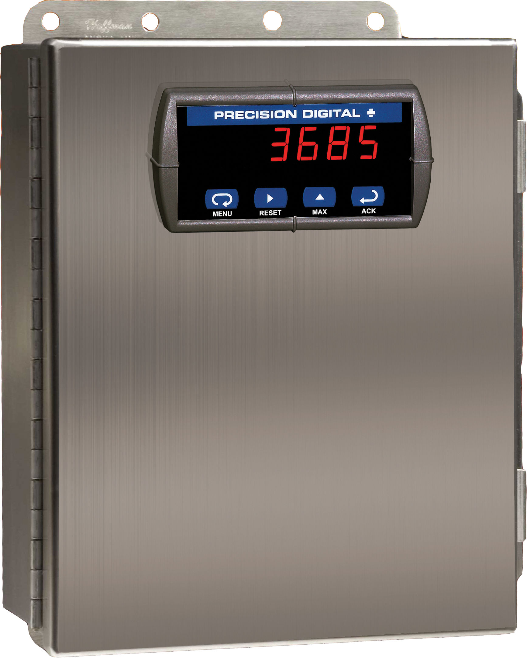
PDA2604-1C
Stainless Steel UL Type 4X Enclosure with (1) Centered Horizontal 1/8 DIN Cutout
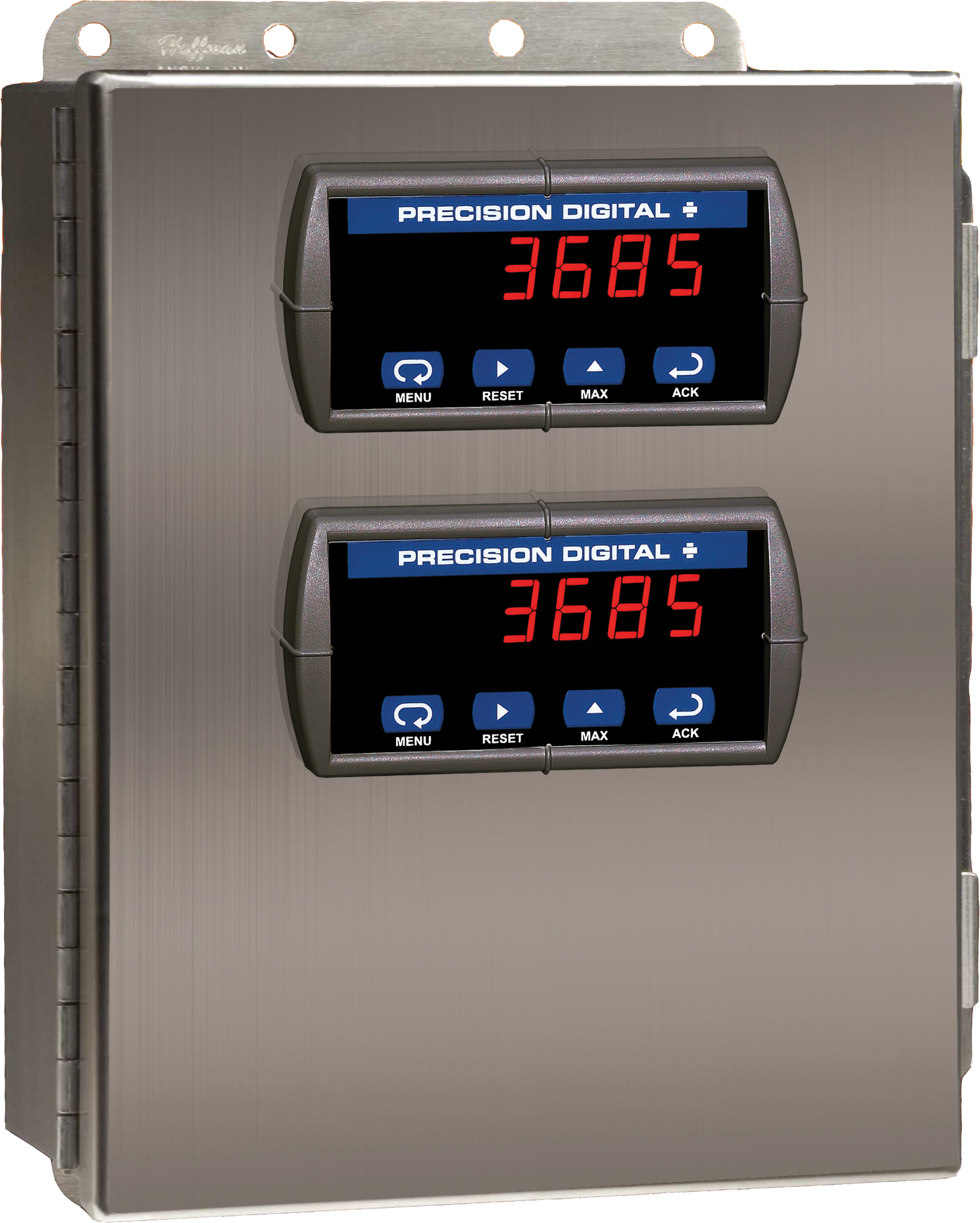
PDA2604-2
Stainless Steel UL Type 4X Enclosure with (2) Horizontal 1/8 DIN Cutouts
PDA2604-2C
Stainless Steel UL Type 4X Enclosure with (2) Centered Horizontal 1/8 DIN Cutouts
PDA2604-3C
Stainless Steel UL Type 4X Enclosure with (3) Centered Horizontal 1/8 DIN Cutouts
PDA2704-1C
Steel UL Type 4 Enclosure with (1) Centered Horizontal 1/8 DIN Cutout
PDA2704-2C
Steel UL Type 4 Enclosure with (2) Centered Horizontal 1/8 DIN Cutouts
PDA2704-3C
Steel UL Type 4 Enclosure with (3) Centered Horizontal 1/8 DIN Cutouts
PDA2605
Stainless Steel UL Type 4X Enclosure with (5) Horizontal 1/8 DIN Cutouts
PDA2622
Stainless Steel UL Type 4X Enclosure with (1) Vertical and (1) Horizontal 1/8 DIN Cutouts