Features
- Nonintrusive Conversion of 30/60/120 Amps to 4-20 mA
- Split Core Convenience
- Compact Design
- +/-2% Full Scale Accuracy from 10% to 100% of Selected Range
- Field Mounting Tabs Provided
Overview
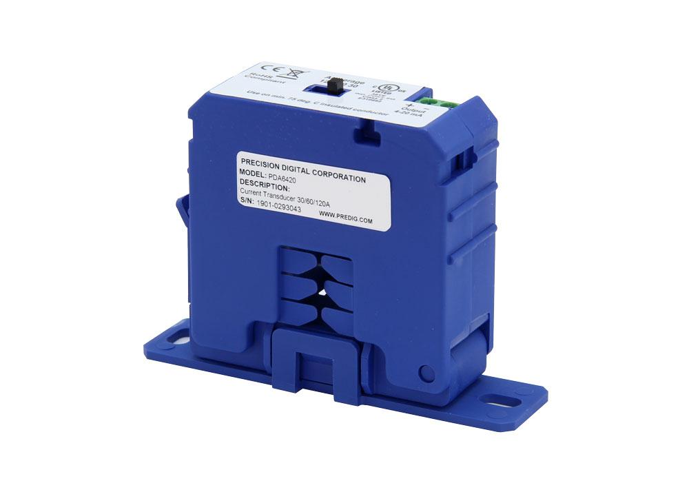
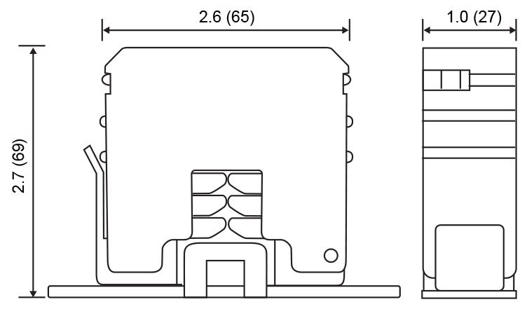
The PDA6420 Current Transducer Device (CTD) converts the current flowing through a cable or wire to a 4-20 mA signal and can be set up in the field to handle inputs of 30, 60, or 120 Amps. This nonintrusive device features split core convenience for easy installation and is a cost-effective solution for monitoring load or proof of operation. The current transducer is ideal for monitoring current loads on pumps, driving fans and blowers, and sensing the status of heating coils and lighting. Current Transducer Devices used for load trending over time are effective sensors for predictive maintenance programs. The PDA6420 requires 24 VDC power and this power can be provided by many Precision Digital meters or by the Precision Digital PDA1024-01 24 VDC power supply.
IMPORTANT: The CTD Current Transducer Device is intended to provide an input to equipment under normal operating conditions. Where failure or malfunction of the current transducer device could lead to personal injury or property damage to the controlled equipment or other property, additional precautions must be designed into the control system. Incorporate and maintain other devices, such as supervisory or alarm systems or safety or limit controls, intended to warn or protect against failure or malfunction of the current transducer device.
Installation

WARNING: Risk of Electrical Shock. Disconnect the power supply before making electrical connections. Contact with components carrying hazardous voltage can cause electric shock and may result in severe personal injury or death.
Wiring
- Disconnect the conductor cable from the power source.
- Snap the split core around the power conductor cable and close the core until the core snaps shut.
- Wire the CTD 4-20 mA output terminals to desired device per Figure 1 and Figure 3.
- Select the input current range at the front panel slide switch. See Figure 4 and Setting the Current Range section.
- Reconnect the power conductor cable. See Figure 1 for a wiring example.
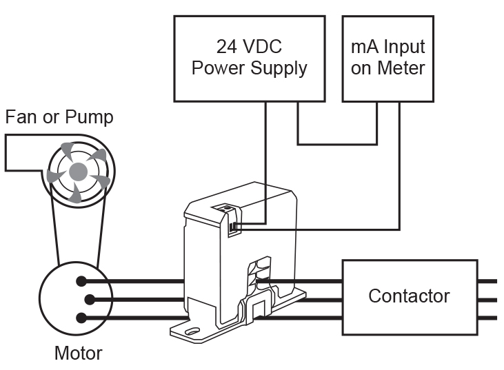
Figure 1: Current Input Applications Example
If the measured current is too low to be detected or it is higher than the maximum current rating of the CTD device, use the following methods to increase or decrease the current:
If Measured Current is Too Low to Be Detected
Wrap the conductor (wire) through the sensing hole and around the CTD body to produce multiple turns to increase the measured current. The measured current is equal to the actual current multiplied by the number of turns (Figure 2).
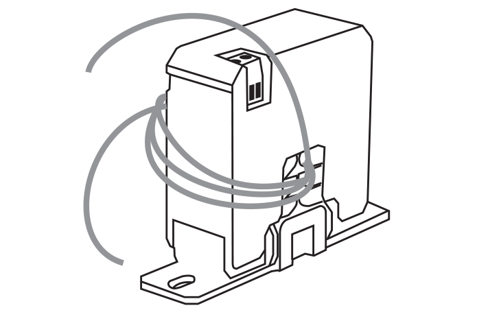
Figure 2: PDA6420 Current Transducer Shown with Four Turns
The controller must be scaled to account for the extra turns. If four turns pass through the transducer as shown in Figure 2, the normal controller reading must be divided by 4.
IMPORTANT: Failure to derate the current capacity could result in damage to the CTD device when using multiple turns to increase the measured current. Use the following formula to determine the new maximum current:
Example: If the new maximum current is equal to the CDT current rating of 120 A, then:
Maximum Current = 120 A / 4 = 30 A
To Monitor Currents Exceeding the Maximum Current Rating of the CTD Device
For currents greater than 120 A, proceed as follows:
- Use the 5 A Current Transformer (PDA6405) to reduce the current passing through the CTD device (Figure 3)
- Run the PDA6405 secondary wire through the sensing hole.
- Terminate the two secondary wires of the 5 A PDA6405 to each other, and then install the 5 A PDA6405 on the monitored conductor.
- Set the CTD device to the lowest current range (30 A)
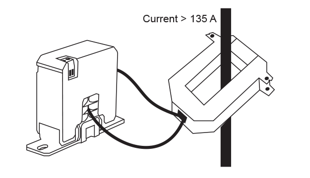
Figure 3: CTD Device with PDA6420 Transformer
Setup
Setting the Current Range
Position the current range slide switch to a level consistent with the load:

Figure 4: Current Setting Switch
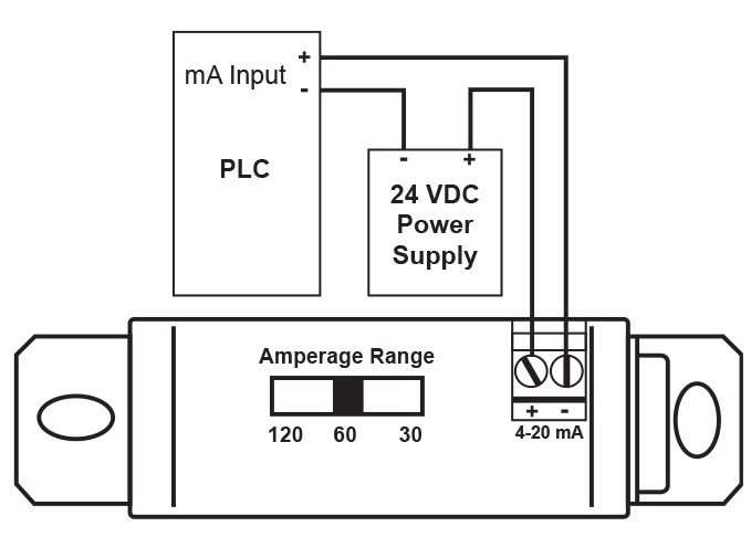
Figure 5: PDA6420 being powered by external 24 VDC power supply such as Precision Digital model PDA1024-01.
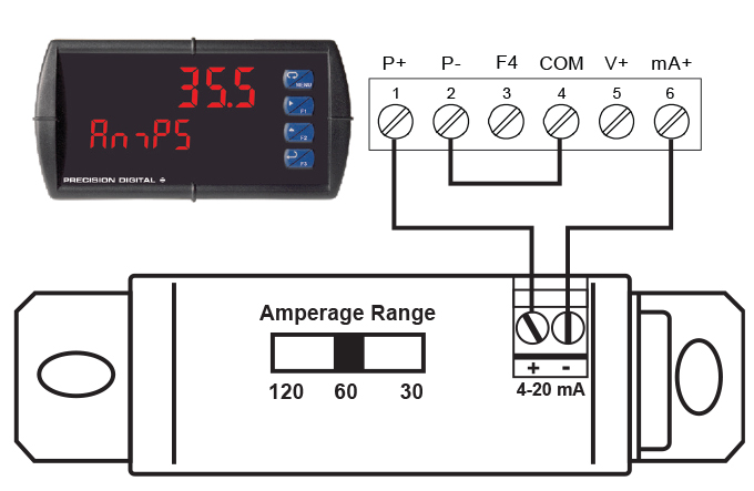
Figure 6: PDA6420 being powered by the Precision Digital PD6000. PD6000 is displaying the current being measured by the PDA6420.
Accessory
24 VDC Transmitter Power Supply
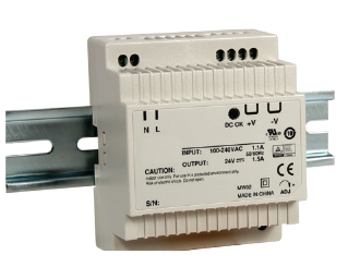
Precision Digital offers the PDA1024-01 for applications that require more than the 200 mA power that the Helios can provide.
| Specifications |
| Output Voltage: |
| 21.6 ~ 26.4 VDC; ±10% 1.5A rated current. |
| Dimensions: |
| 3.07" x 3.66" x 2.20" (78 mm x 93 mm x 56 mm) (W x H x D) |

