General
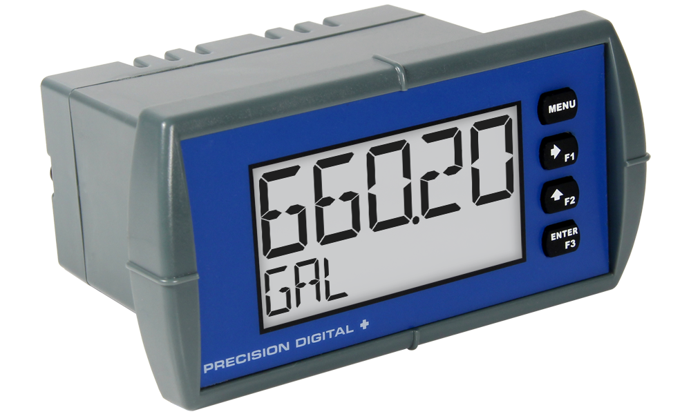
Display: Five digits: -99999 to 99999, 0.60" (15.2 mm) high, 7-segment, automatic lead zero blanking.
Engineering Units: 0.25" (6.4 mm) high, 14-segment.
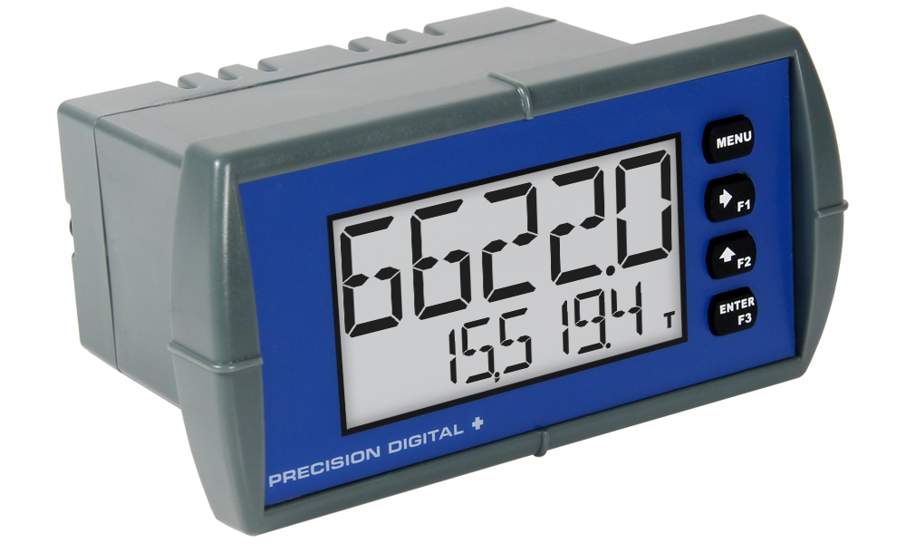
Bargraph: 20-segment, 0% to 100% indication.
Trend arrows: Up and down trend indication.
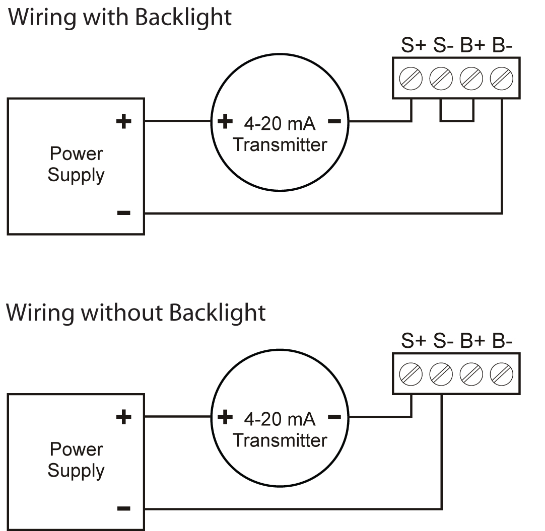
Backlight: Bright orange (intensity varies with signal)
Display Update Rate: 2.5/second
Overrange: Display flashes 99999
Underrange: Display flashes -99999
Programming Method: Four front panel buttons
Noise Filter: Programmable from 1 to 199
Recalibration: Recommended at least every 12 months.
Max/Min Display: Max/min readings reached by the process are stored until reset by the user or until power to the meter is turned off.
Password: Programmable password restricts modification of programmed settings.
Non-volatile Memory: All programmed settings are stored in non-volatile memory for a minimum of ten years if power is lost.
Voltage Drop: 2.0 V max w/o backlight, 5.7 V max with backlight
Equivalent Resistance: 125 Ω @ 20 mA w/o backlight, 315 Ω @ 20 mA with backlight
Normal Mode Rejection: 64 dB at 50/60 Hz
Operating temperature range: -30 to 65°C
Allowable Temperature Range: -40 to 65°C* (see note below)
Storage temperature range: -40 to 65°C
Relative humidity: 0 to 90% non-condensing
Connections: Screw terminals accept 12 to 22 AWG wire
Enclosure: 1/8 DIN, high impact plastic, UL 94V-0, color: gray
Mounting: 1/8 DIN panel cutout required. Two panel mounting bracket assemblies provided
Tightening Torque: 4.5 lb-in (0.5 Nm) Screw terminal connections
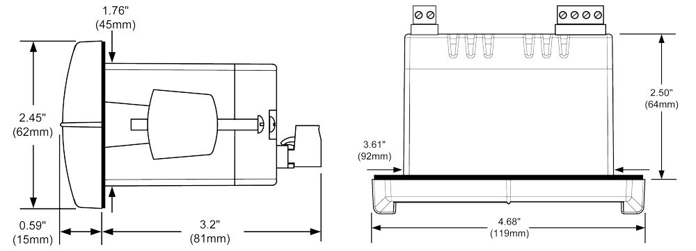
Overall Dimensions: 2.45" x 4.68" x 4.19" (62 x 119 x 106 mm)
Weight: 5.7 oz (162 g)
Warranty: 3 years parts & labor
Input
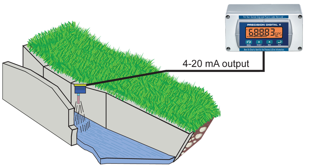
Input Range: 4-20 mA
Accuracy: ±0.03% of span ±1 count, square root and programmable exponent: 10-100% FS
Calibration: Scale without signal or calibrate with signal source
Calibration Range: User programmable over entire range of meter
Minimum Span: 0.40 mA between input 1 and input 2
Note: An Error message will appear if input 1 and input 2 signals are too close togetherInput Overload: Over current protection to 2 A max.
HART Transparency: Analog input will not interfere with existing HART communications on the wired 4-20 mA signal
Decimal Point: Up to four decimal places (d.dddd, dd.ddd, ddd.dd, dddd.d, or ddddd)
Function: Linear, square root, or programmable exponent
Low-Flow Cutoff: -99999 to 99999 (-99999 disables cutoff function)
Temperature Drift: 50 PPM/°C from -40 to 65°C ambient
*Below -30°C the LCD becomes less readable.PD688 Approvals for Hazardous Locations
FM Approved & CSA Certified as intrinsically safe with entity for use in Class I, Div 1, Groups ABCD; Class II, Div 1, Groups EFG; Class III, Div 1; Class I, Zone 0, Group IIC; T-code = T4. Non-incendive: Suitable for use in Class I, Div 2, Groups ABCD; Class II, Div 2, Groups FG; Class III, Div 2.
Entity Parameters: Ui: 30 V; Ii: 175 mA; Ci: 0; Li: 0; Pi: 1.0 W
ATEX II 1G, Ex ia IIC T4, IP65, Ta = -40°C to 65°C
Note: Installation must be performed in accordance with Control Drawing LIM688-2
Disclaimer
The Information contained in this document is subject to change without notice. Precision Digital Corporation makes no representations or warranties with respect to the contents hereof, and specifically disclaims any implied warranties of merchantability or fitness for a particular purpose.