General
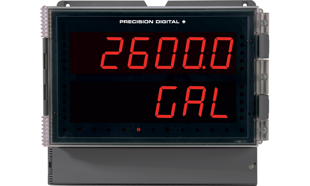
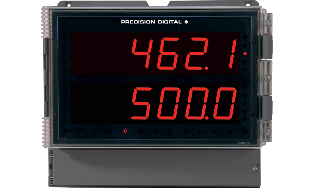
Display: 1.0" (25.4 mm) red LED, 4½ digits
Enclosure: Impact-resistant glass-filled polycarbonate, NEMA 4X, IP67 (IEC 529), color: gray (RAL 7035). Two holes for ½" conduit provided at base.
Mounting: Enclosure contains four holes for wall-mounting. Panel mounting and 2" pipe mounting kits available.
Overall Dimensions: 6.7" x 5.5" x 3.7" (170 x 140 x 95 mm)
Weight: 3.8 lb (1.73 kg)
Alarm Points: Four, any combination of high or low alarms
Alarm Point Deadband: 0-100% FS, user selectable
Alarm Status Indication: Front panel LED
External Programming: The Enter button function scan be controlled externally by wiring a switch across terminals EN and CM.
Non-Volatile Memory: Settings stored for a minimum of 10 years.
Normal Mode Rejection: 64 dB at 50/60 Hz
Power Options: AC power: 115 or 230 VAC (field select) ±10%, 50/60 Hz, 12 VA. DC power: 22-28 VDC; 12 W maximum.
Isolation: AC powered: 1500 V; DC powered: 500 V
Connections: Removable screw terminals accept 12 to 22 AWG
Warranty: 2 years parts & labor
Basic Meter Specifications
Inputs: Field selectable: 4-20 mA, 0-20 mA, 0-5 V, 1-5 V, 0-10 V
Display: 6 digits, red LED, -19,999(0) to 29,999(0) with selectable extra zero. Total display: 0 to 999,999.
Decimal Point: Process/rate: 2.9999, 29.999, 299.99, 2999.9 or 299990. Total: 9.99999, 99.9999, 999.999, 9999.99, 99999.9, 999999. Rate and total decimal points are independent.
Linear Input Accuracy: ±0.05% FS ±1 count
Root Function Accuracy: ±0.1% FS ±2 counts
Programmable Exponent: From 1.0001 to 2.9999
Multi-Point Linearization: 2 to 11 points
Calibration: May be scaled using internal calibration ( ) or calibrated by applying an external calibration signal (
 ). To scale inputs such as 0-5 V, 1-5 V, or 0-10 V without applying a signal it is necessary to first complete an Initial Calibration.
Calibration Range: User programmable over entire range of meter
Input
Range | Minimum Span Between
1 & Input 2 |
| 0-5 V | 0.16 V |
| 0-10 V | 0.32 V |
| 4-20 mA | 1.60 mA |
11-Point Linearization: Minimum span between inputs
| Input Range | ..... | Minimum Span |
| 4-20 mA | ..... | (1.6 mA / (Number of points -1)) |
| 0-5 V | ..... | (0.16 V / (Number of points -1)) |
| 0-10 V | ..... | (0.32 V / (Number of points -1)) |
e.g. Minimum span for an 11-point, 4-20 mA calibration is 0.16 mA between inputs.
Input Impedance: Voltage ranges: greater than 300k Ω; current ranges: 100 Ω
Transmitter Supply: Two isolated transmitter supplies, 24 VDC ±5% @ 20 mA each, regulated.
Maximum loop resistance: 1200 Ω
Max (Display Peak): Captures the maximum or peak process/rate and displays it via the front panel ENTER button ( )
)
Max Indication: Front panel flashing "R" LED
Lockout: Jumper JP1 labeled "LOCK" restricts modification of programmed settings.
Operating Temperature: -20 to 65°C
Storage Temperature: -40 to 85°C
Relative Humidity: 0 to 90% non-condensing
Rate/Totalizer/Batch Controller Features
Rate Display Indication: LED labeled "R" in lower right illuminates when meter is displaying rate or process input.
Alternating Display: Display may be programmed to alternate between rate and total every 10 seconds.
Low-Flow Cutoff: Any input below the low-flow cutoff value will result in a display of zero. May be set from 1 count to 100% FS, user selectable. To disable low-flow cutoff, program cutoff value to zero. Totalizer is based on rate display; inputs below the low-flow cutoff value will not affect the totalizer.
Total Display: 0 to 999,999, automatic lead zero blanking
Total Decimal Point: May be set in any of the following positions: 9.99999, 99.9999, 999.999, 9999.99, 99999.9, 999999. Total decimal point is independent of process/rate decimal point.
Time Base: Seconds, minutes, hours, or days
Total Conversion Factor: Programmable from 0.00001 to 59999
Totalizer: Calculates total based on rate and field programmable multiplier to display total in engineering units. Total is stored in non-volatile memory.
Totalizer Rollover: Totalizer rolls over when total exceeds 999,999. Relay status reflects the display value.
Totalizer Presets: Up to four, user selectable under Setup menu. Any set point can be assigned to total and may be programmed anywhere in the range of the meter. Relays assigned to total trip when total reaches the preset value and reset when total is reset to zero or when acknowledged manually. Can be programmed so when the highest preset value is reached the total automatically resets to zero.
Preset Offset: Relays that are assigned to total can be programmed to trip at any point below the next relay's preset value. If preset offset mode is selected the corresponding relay will always trip at a programmed offset value before the next relay trips.
Example: Set point 1 and 2 are set up for total, with Offset selected (under set point 2). If the preset offset is set at 10, (during Set Points programming for set point 1), then relay 1 will trip 10 counts before relay 2.
Programmable Delay on Release: If the meter is programmed to reset total to zero automatically when the highest preset is reached, there will be a delay before the total relays are reset. This delay can be programmed between 1 and 999 seconds.
Priority Batch Programming: This feature allows the user to quickly change preset values without going into the main menu by holding the ENTER button for more than 3 seconds.
Total Reset: Via front panel ENTER button, external contact closure, or automatically via user selectable preset value.
Total Reset Lockout: Meter may be programmed
Rating: 2 or 4 Form C (SPDT); rated 2 A @ 30 VDC or 2 A @ 250 VAC resistive load; 1/14 HP @ 125/250 VAC inductive
Assign to Process/Rate or Total: Any relay may be assigned to process/rate or total (process/rate meters).
Built-in Suppression: Each relay contact is protected by a built-in suppressor (snubber) to prolong the life of the relays and provide a degree of protection against electrical noise caused by inductive loads. Suppressors value: 0.01 ;µF/470 Ω, 250 VAC.
Deadband: 0-100% FS, user selectable
High or Low Alarm: User may program any alarm for high or low
Relay Operation: Latching or non-latching
Fail-Safe Operation: Relay coils are energized in non-alarm condition. In case of power failure, relays will go to alarm state. Fail-safe operation may be disabled, by removing jumper J5 located on the options board.
Auto Initialization: When power is applied, relays assigned to total will reflect the state of the accumulated Total value in memory. Relays assigned to process/rate or temperature will reflect the state of the input to the meter.
Relays Reset: User select via jumper array and  menu Total Relays Reset (process/rate meters):
- When total is reset to zero, if set up for external
total reset. - After delay has elapsed, if set up for internal total reset.
- Manual any time, if set up for external total reset. Manual reset resets all manually resettable relays.
Process/Rate & Temperature Relays Reset:
Relays assigned to process/rate or temperature may be programmed to reset in any of the following ways:
- Automatic reset when the input passes the reset point.
- Manual reset at any time (via user supplied external contact closure at terminals AK and CM or front panel ACK button). Manual reset resets all manually resettable relays.
- Automatic plus manual reset at any time. Relays will automatically reset when input passes the reset point. Relays can also be manually reset at any time (via user supplied external contact closure at terminals AK and CM or front panel ACK button). Manual reset resets all manually resettable relays.
- Manual reset only after alarm condition corrected. Relays can be manually reset only after alarm condition has been corrected (via user supplied external contact closure at terminals AK and CM or front panel ACK button). Manual reset resets all manually resettable relays.
Isolated 4-20 mA Transmitter Output
Scaling Range: Anywhere in range of meter, 501 counts minimum span for process/rate meter; reverse scaling allowed.
Accuracy: ±0.1% FS ±0.004 mA
Output Loop Resistance:
| | Loop Resistance |
| Power supply | Minimum | Maximum |
| 24 VDC | 10Ω | 600Ω |
| 35 VDC (external) | 600Ω | 1000Ω |
Isolation: 500 V input-to-output or input/output-to-24 VDC supply
External Loop Power Supply: 35 VDC maximum
The PD650, PD655, and PD656 are ideal for loops that consist of a transmitter, a digital meter, and a DCS or computer because they can provide isolated power to drive both the input and output loops.
Batch Control with Varying Batch Sizes
To simplify batch control applications with varying batch sizes, use one or more switches to control the relay outputs. The switch allows the operator to disable the process when changing presets in the meter and then enable the process after all the changes have been made and the process is ready to resume. The switch serves as a "Stop/Ready" control.

