


Features
- 4-20 mA Loop Set Point Generator
- Panel Mount or NEMA 4X
- 4-20 mA or 3-21 mA Output Ranges
- Set Point Displayed as 0-100%, 4-20 mA, or 3-21 mA
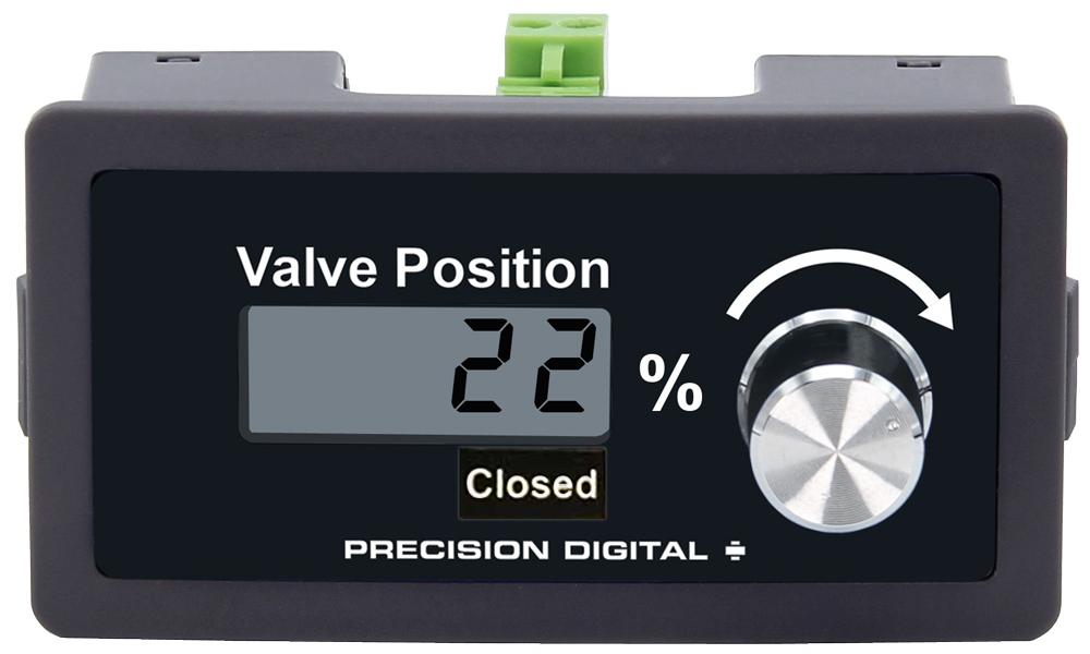
- Valve Position Displayed as 0-100%
- Built-in Dial for Changing Output
- Backlit Display
- Coarse or Fine Set Point Adjustment
- ± 0.5% Output Accuracy
- 0.01 Display Accuracy
- 15-30 VDC Power Requirement
- < 500 ohms Sampling Resistance
- Decals Provided for %, mA, Open, Closed, and Custom
Overview
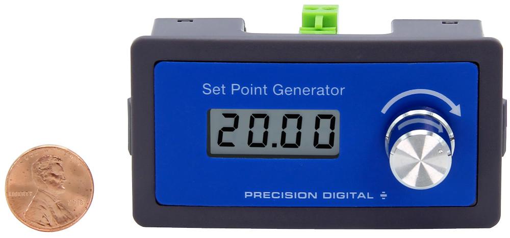
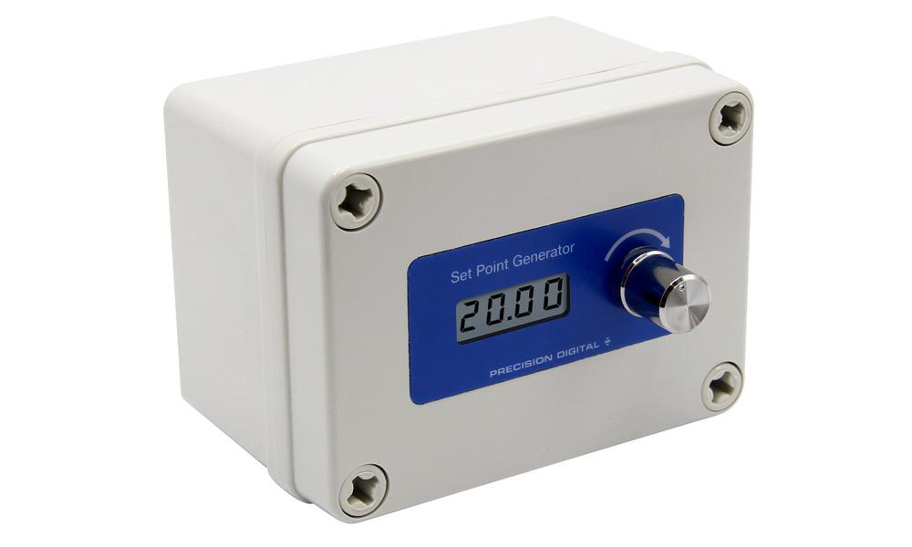
The PD420/21 set point generator and the PD460/61 valve positioner provide a convenient way to generate a 4-20 mA signal that can be used to control another device.
Both feature a backlit LCD. The PD420/21 set point generator can be programmed to display 0-100%,
4-20 mA or 3-21 mA and output either 4-20 mA or 3-21 mA. The PD460/61 valve positioner is programmed to display a value of 0-100% relating to the 4-20 mA output. A built-in dial is provided to vary the displayed / output value. The dial may be programmed for coarse or fine adjustment.
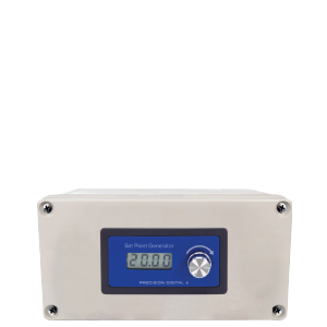
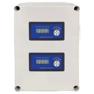
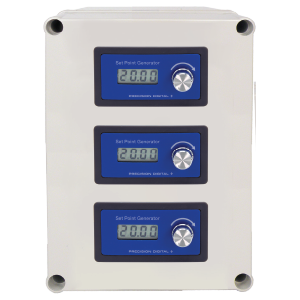
The signal generator and valve positioner are both available as a panel mount or NEMA 4X version. In addition, NEMA 4X enclosures are provided to house up to three of the panel mount versions.
Decals are provided for %, mA, Open, and Closed for the user to apply to the faceplate. There is also a decal with a white background for the user to write a custom label.
Available Enclosures
Connections
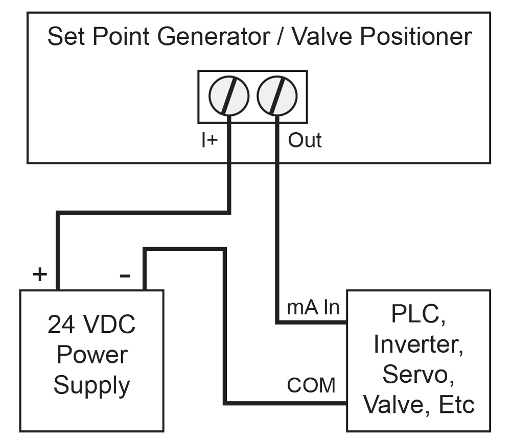
Set Point Generator / Valve Postioner
Powered by 24 VDC Supply
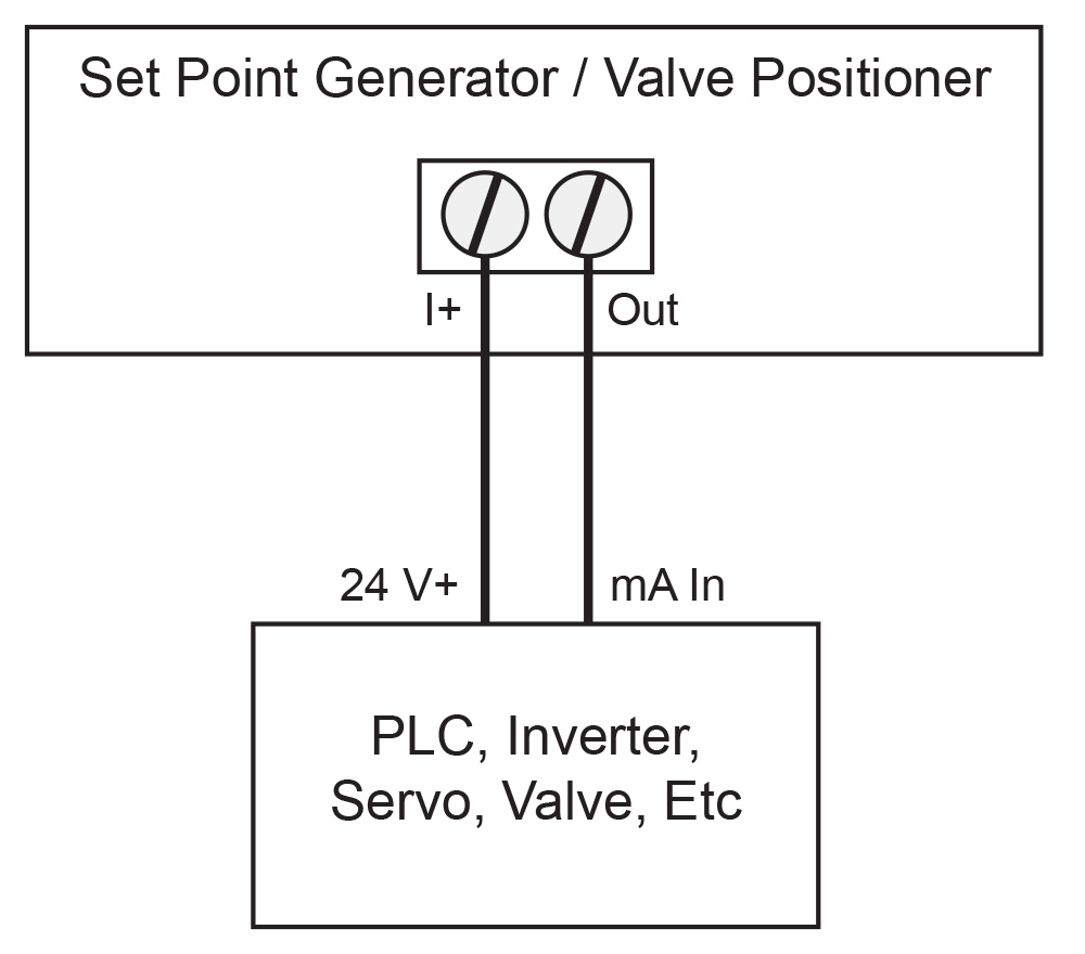
Set Point Generator / Valve Postioner
Powered by Controlled Device
Dimensions Units: Inches (mm)
PD420/60 Panel Mount Dimensions
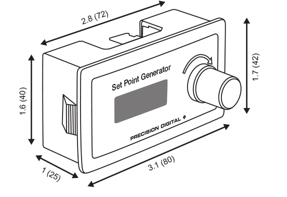
Front View
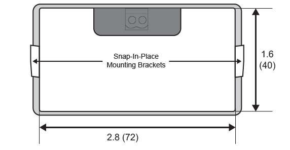
Back View
Notes:
- Panel cutout required: 3.0" x 1.6" (77 mm x 40 mm)
- Panel thickness: must be greater than 0.06" (1 mm)
- Mounting brackets snap in place for easy mounting
PD421/61 NEMA 4X Dimensions
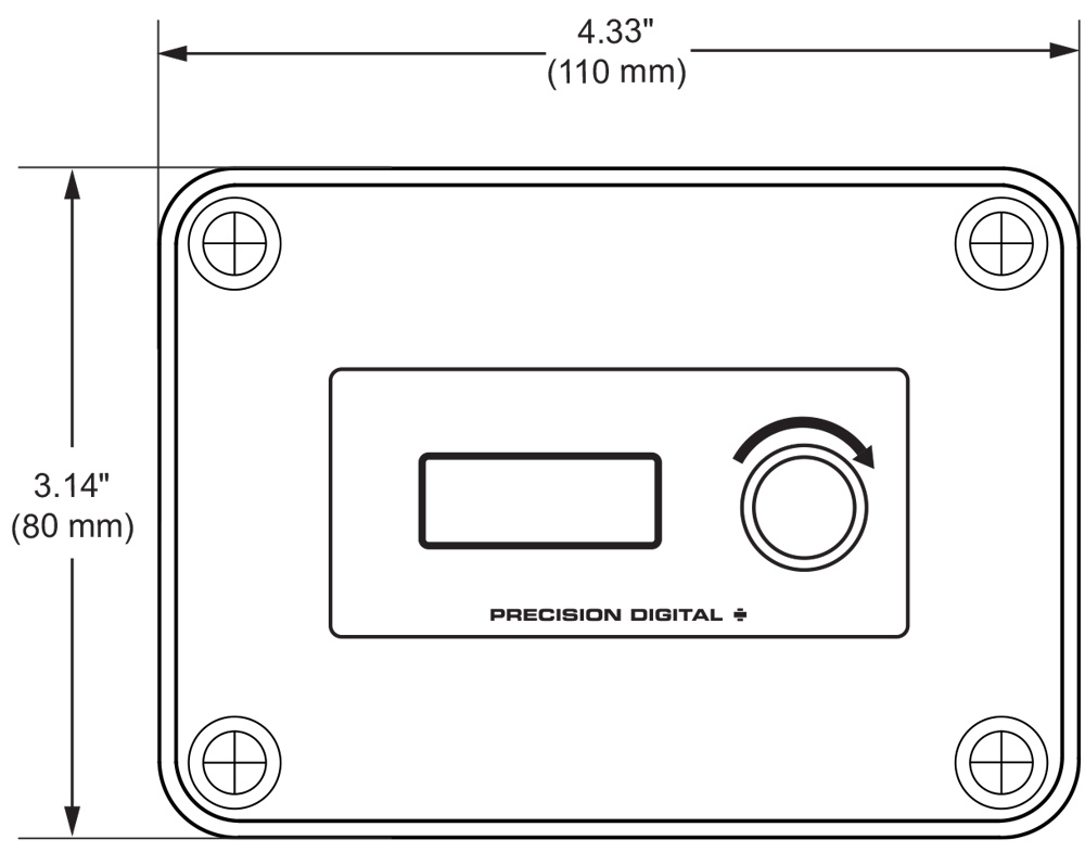
Front View
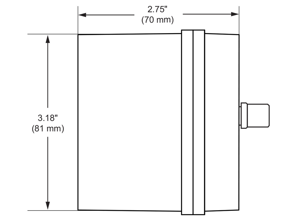
Side View