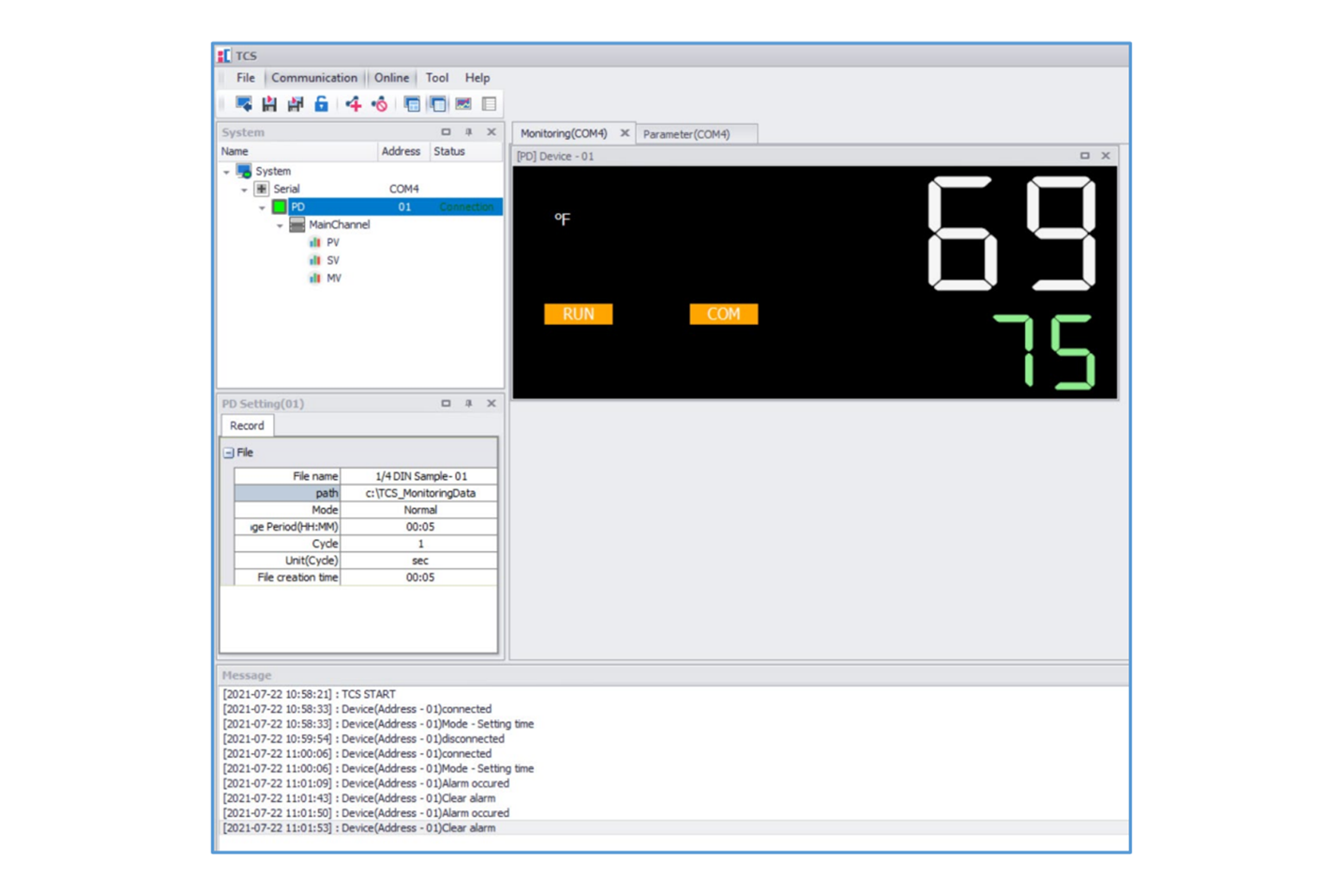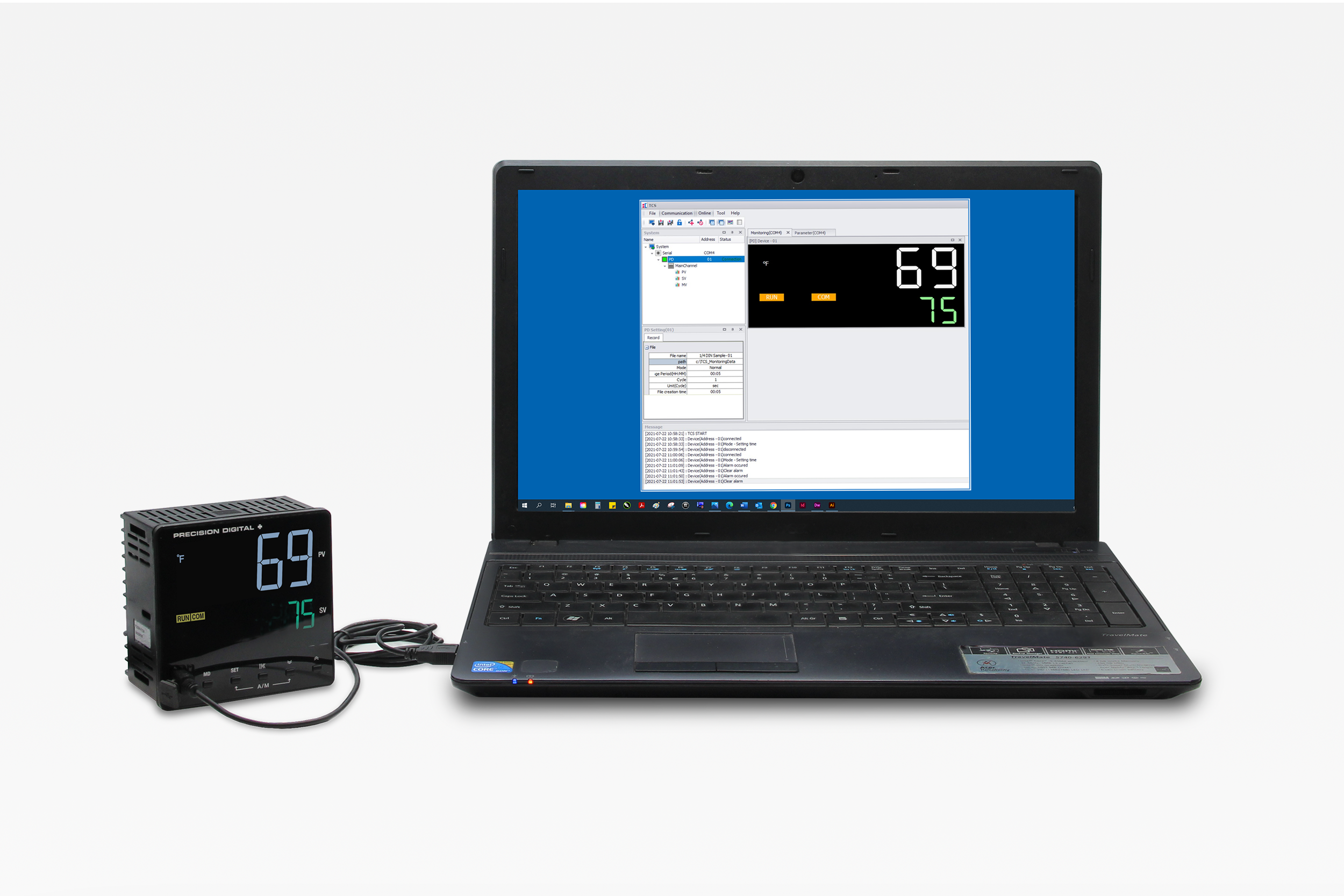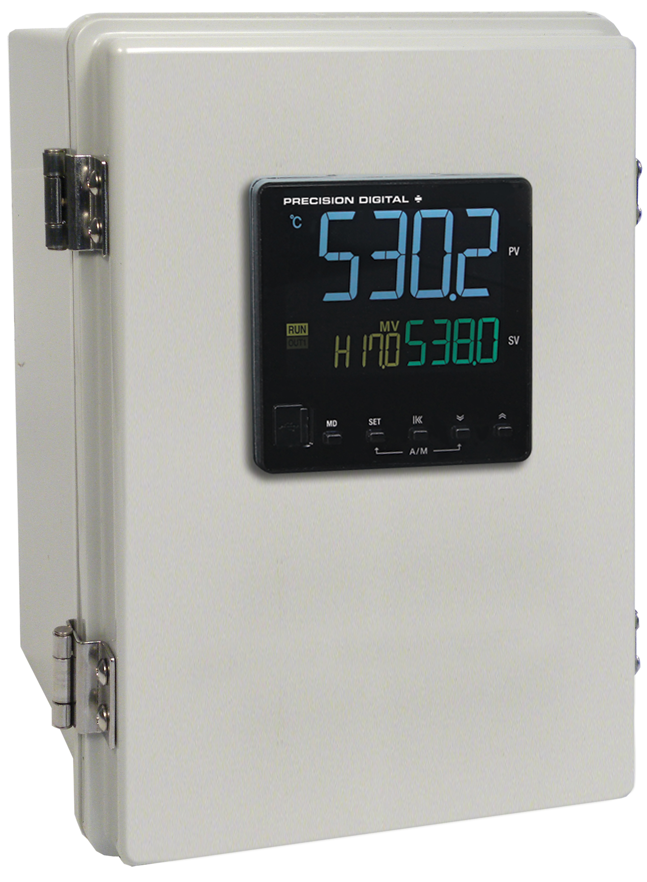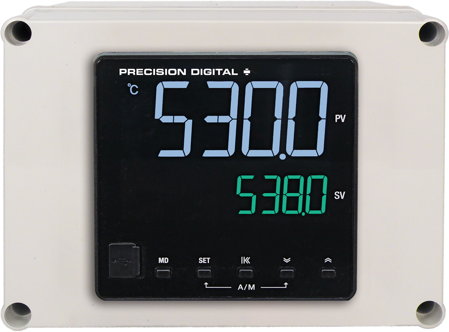

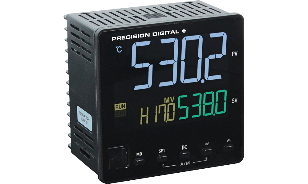


The SuperNova line of controllers includes the free SuperNova TCS monitoring and programming software. The easiest and quickest way to connect to the SuperNova TCS software is to use the on-board mini-USB port available on all SuperNova controllers.
This software can be used for monitoring, data logging, programming, and troubleshooting SuperNova controllers.
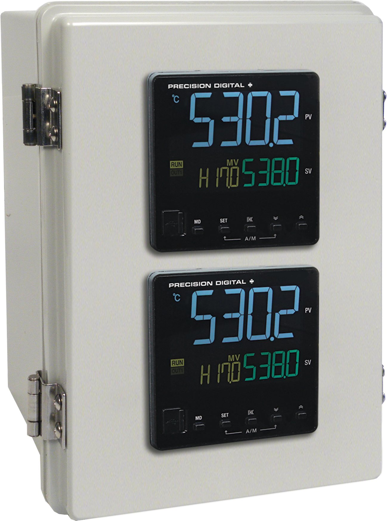
SuperNova TCS software can connect to a maximum of 31 units when using the RS-485 communications option. A single unit can be connected via the USB connection.