
Consider the PDA6405
If you are monitoring high AC current loads on pumps, driving fans and blowers, or sensing the status of heating coils and lighting, you may want to consider using a transformer.
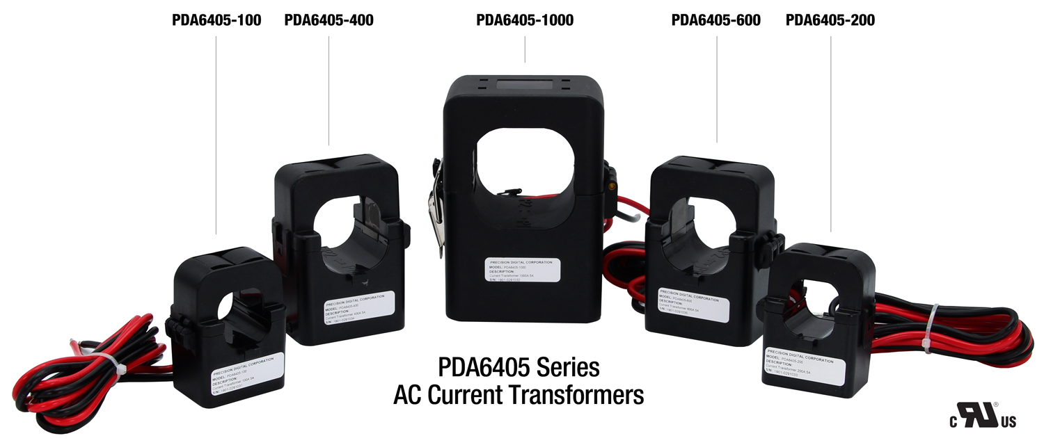
With our recent introduction of a line of split core AC current transformers, Precision Digital can now provide you with a convenient way to measure AC current up to 1000 Amps. The transformer steps down the high current to a 0-5 AAC signal that can be inputted directly into the meter.
The PD6400 also has a second input that can be used to display voltage up to 300 VAC.
The PDA6405 line of transformers can convert the high AC current flowing through a cable or wire to a 0-5 AAC output and are available in ranges of 100, 200, 400, 600, and 1000 AAC. These nonintrusive devices feature split core convenience for easy installation and are a cost-effective solution for monitoring load or proof of operation.
Use the PDA6405 with the PD6400 High Voltage and Current Meter
The PDA6405 transformers are ideal to use with Precision Digital’s PD6400 or PD2-6400 high voltage and current meters because they will accept the 0-5 Amp AC output from these devices.
These meters feature a dual line display that can show the current on the upper display and the units on the lower display. They can also be equipped with relays for alarm and control purposes and a 4-20 mA output signal.
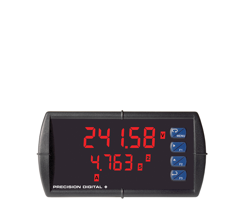
PD6400 High Voltage & Current Meter
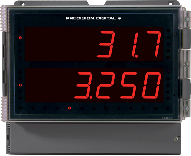
PD2-6400 High Voltage & Current Meter
The following diagram illustrates how the PDA6405 AC current transfomer and the PD6400 digital panel meter are measuring current of the 75 ACC motor.
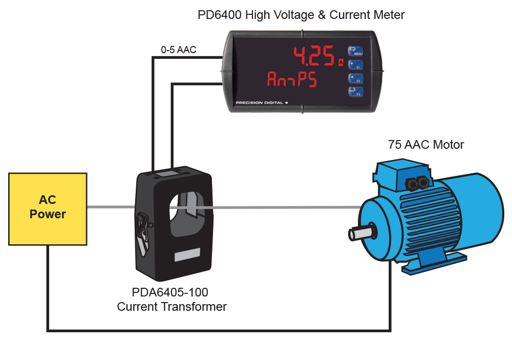
Figure 1: Measuring Current with PDA6405-100 Current Transformer and PD6400 digital panel meter
Wiring the PDA6405 AC Current Transformer
- Disconnect the conductor cable from the power source.
- Snap the split core around the power conductor cable and close the core until the core snaps shut.
- Wire the output leads to desired device as shown in figure 1.
- Reconnect the power conductor cable. See figure 2 below for a wiring example.
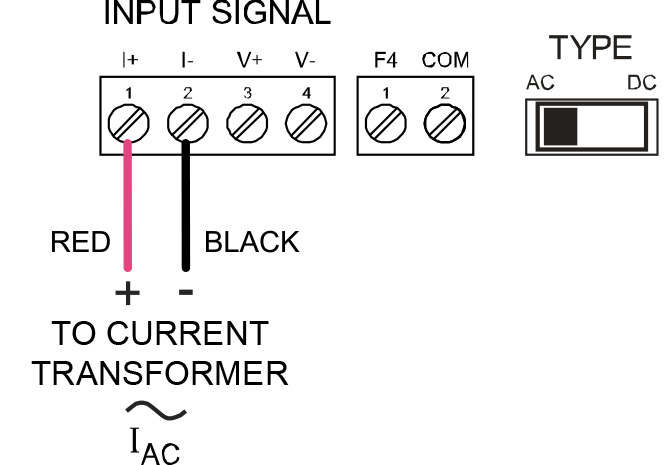
Figure 2: PD6400 Connections from PDA6405 Current Transformer with AC Switch Selected
If the measured current is too low to be detected use the following method to increase the current:
Wrap the conductor (wire) through the sensing hole and around the current transformer body to produce multiple turns to increase the measured current. The measured current is equal to the actual current multiplied by the number of turns. See figure 3 for example.
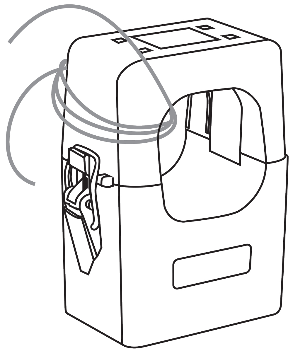
Figure 3: PDA6405 Current Transformer Shown with Four Turns
The controller must be scaled to account for the extra turns. If four turns pass through the transducer as shown in figure 1, the normal controller reading must be divided by 4.
IMPORTANT: Failure to derate the current capacity could result in damage to the current transformer when using multiple turns to increase the measured current. Use the following formula to determine the new maximum current:
The new maximum current is equal to the current transformer current rating divided by the number of turns.