Features
- FREE Download
- Easily Configure PD6730X/PD6830X Modbus Scanners
- Manage Scanner Settings
- Download Data Logs
- Set Up K-Factor, Scaling, Tag, Units, & More
- Scale & Configure 4-20 mA & Pulse Outputs
- Save & Load Scanner Configurations
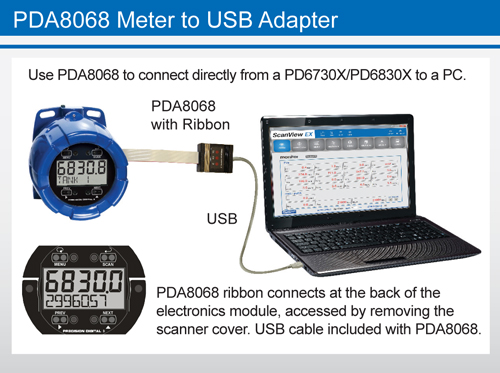
- Easy to Connect with the PDA8068 Meter to USB Adapter
Overview
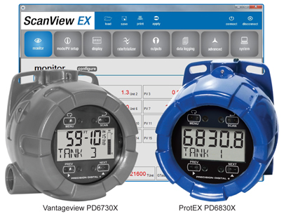
Configure any Vantageview PD6730X Safe Area Modbus Scanner or any ProtEX PD6830X Explosion-Proof Hazardous Area Modbus Scanner using the PC-based ScanView EX software. ScanView EX is available as a free download (adapter required). ScanView EX makes complete scanner configuration quick and easy. Copying one scanner configuration to another, as well as saving or retrieving a scanner's configuration file, is a snap. ScanView EX's intuitive layout and easy-to-understand interface make any scanner configuration simple to complete. A PDA8068 meter-to-USB adapter is available for a quick & easy PC connection. ScanView EX is an extremely useful tool that eliminates a lot of button pushing and minimizes any confusion when setting up a PD6730X or PD6830X.
Connections
Connection Options
With ScanView EX software, there are a variety of options to connect your Vantageview PD6730X or ProtEX PD6830V scanner to a PC for programming, depending on the PC's available hardware.
To connect a PC with a USB connection directly to a PD6730X/PD6830X, use the PDA8068, a PD6830X/PD6730X to USB adapter as seen in the graphic below. To do so, begin by removing the cover from the scanner. Turn the spring-loaded thumb screws on the faceplate counter-clockwise and remove the electronics module from the enclosure carefully. Turn the electronics module over to expose the ribbon connector at the rear. The ribbon connection is made to the connection board of the scanner; disconnect the ribbon from the connection board by pushing the connector tabs to the outside. Connect the PDA8068 to the electronics module using the the ribbon connector of each and plug the USB connection into the PC.
Start up ScanView-EX software and you are ready to begin programming. Once programming has been completed, simply disconnect the adapter from the electronics module and reconnect the connector board to the electronics module. Screw the electronics module back into the enclosure and put the cover back on the scanner.
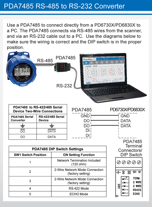
To connect a PC with an RS-232 connection to a PD6730X/PD6830X, use the PDA7485, an RS-485 to RS-232 adapter, as seen in the graphic below. The scanner uses a two-wire RS-485 connection. The PDA7485 contains five terminal connections plus a five position DIP switch. The factory settings allow the adapter to work in this configuration. Check the connections, using the the information below, to be sure they are correct. Connect the PDA7485 to the PC using an RS-232 cable. Start up ScanView-EX software and you are ready to begin programming.
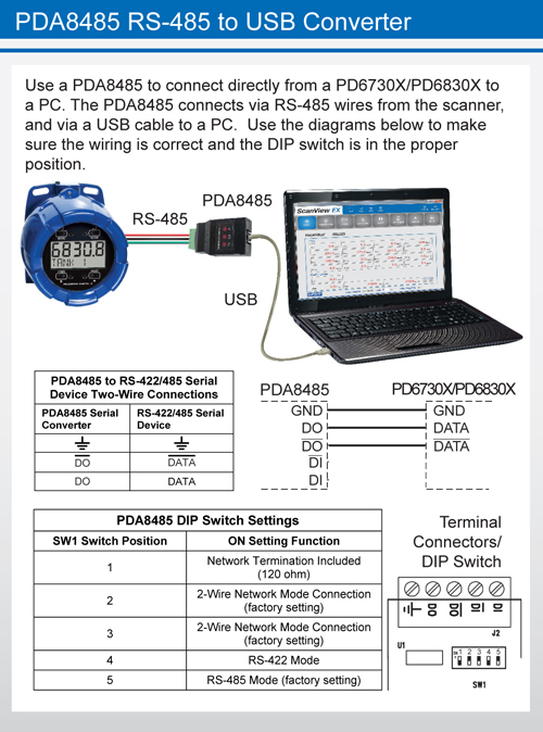
To connect a PC with a USB connection to a PD6730X/PD6830X using the RS-485 connections, use the PDA8485, a USB to RS-485 converter, as seen in Figure 4. The scanner uses a two-wire RS-485 connection. The PDA8485 contains five terminal connections plus a five position DIP switch. The factory settings allow the converter to work in this configuration. Check the connections, using the the information in the graphic below, to be sure they are correct. Connect the PDA8485 to the PC using a USB cable. Start up ScanView-EX software and you are ready to begin programming. Additional information regarding the use of Precision Digital adapters and converters is available here on our website.
Configuration
With ScanView EX software, it is a simple process to configure your Vantageview PD6730X or ProtEX PD6830X scanner. Navigate quickly and clearly through the screens and drop-down menus to set up Units, Displays, Relays, K-factor, Analog Outputs, and more. All variables, alarms, and data logging parameters can be configured. Monitor view configurations may be safed as ".mcf" files, and scanner parameter settings saved as ".mve" files and can be loaded at any time from the ScanView EX folder on the computer's C: Drive: C:\PDC\ScanView EX 1.00\Meter Data. To create configuration files, load the default configuration file, change the settings, then save as a new configuration file. Configurations can also be printed (click Print), and print in list form.
Initial Communications Setup
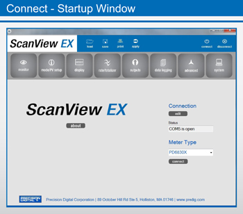
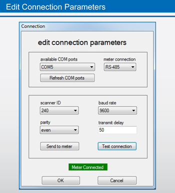
When connecting to a meter using ScanView EX, simply click on the Connect menu or Connection menu edit button in the initial startup window, and the Edit Connection parameters menu appears.
On the left side of the window, there is a drop-down menu of available communication ports. If you don't see your port listed, refresh the COM List. The scanner's connection status can be seen at the bottom of the window; a green box indicates that the scanner is connected. The user is able to check the connection at any time by pressing the Test Connection button.
The software serial settings are visible in this window. The information associated with each parameter should be entered by the user. The scanner ID is the scanner's unique address identification. The default scanner ID is 240. The baud rate, parity, and transmit delay should match those of the device being connected to, or communication breaks may occur. Select from the drop-down menu choices. The user can send the settings to the meter when the information has been entered.
For specified images below, click the button below the image to see a larger representation.
Monitor Screen
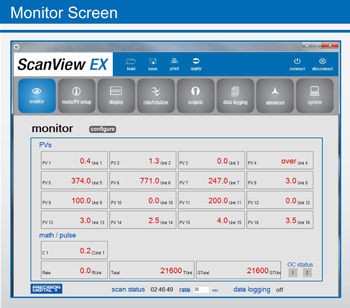
The Monitor Screen is where the operator can monitor readings from, and status of, a programmed PD6730X or PD6830X. The Monitor Screen is divided into two parts: PVs and Math/Pulse.
PVs is where the operator will find up-to-date readings for any of sixteen individual process variables; each is programmed individually to display information in selected engineering units with custom tags.
The Math/Pulse section is where the operator can view displayed information on enabled math channels, as well as Rate, Total, and Grand Total. Math channels will only display if they are enabled.
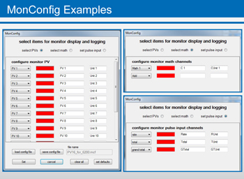
All parameters in the Monitor Screen can be enabled in the configuration window, which is accessed by clicking the Configure button. In the MonConfig window, there are three buttons to choose from: Select PVs, Select Math, and Set Pulse Input. Once PVs, Math Channels, or Pulse Inputs have been enabled and programmed, click Set to activate the selections.
Monitor views can be saved to or loaded from the program's data folder located on the C:\ Drive. Monitor view configurations may be saved as ".mcf" files. Examples of each configuration window can be seen below. The Monitor Screen also enables the operator to see the scan status and rate, which can be changed. The status of Data Logging, on or off, can be seen here also.
Mode/PV Setup Screen
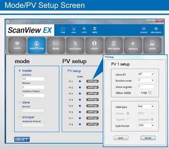
The Mode/PV Setup Screen is divided into two parts: Mode and PV Setup. For the Mode Menu, the choices are Master, Slave, or Snooper. For PV Setup, all enabled PVs from PV1 through PV16 will be displayed with a Settings button next to each. For Mode, the operator selects the desired parameter by clicking on the radio button to the left of the setting. For Master Mode, enter the poll time in seconds, the timeout data, and the number of retries before a communication break occurs. For Slave Mode, enter the timeout data. For Snooper Mode, enter the response timeout data.
For PV Setup parameters, click the Settings button next to each desired PV. A popup window will appear which shows the information associated with that particular PV. The operator then selects from the drop-down menus the Slave ID (1-247 or disable) and the Function Code (3, 4, or 65). The Slave Register Number is entered in the box, and if the register number is a six-digit register, then the box should be checked (the Offset value will automatically update to reflect a five or six-digit register).
The data type is selected from the drop-down menu; the choices are Short (short integer), Long (long integer), or Float (floating data type). When Float is chosen, the only parameter left to select is Byte Format, which references big-endian, little-endian, or swapped (1234, 4321, 2143, or 3412) byte formats. When Short or Long is chosen from the drop-down menu, the additional selection choices appear for Binary or BCD, as well as signed or unsigned data packets. A sample of the PV Setup Screen can be seen in the inset at left.
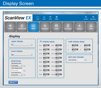
Display Screen
The Display Screen is divided into six sections - Upper Display, Lower Display, Dwell Times, PV Display Setup, Math Display Setup, and Tank Size Indicator. For Upper Display parameters, the choices from the drop-down menu are PV, PV & Units, Tag & Units, and Tag & PV & Units. For the Lower Display parameters, the drop-down menu choices are Tag, Units, Tag & Units, or Off.
The Dwell Times refer to the Tag Display Time, the Units Display Time, and the Scan Display Time. Each of these has a drop-down menu that the operator can use to select times in seconds, from one to five seconds, or Off.
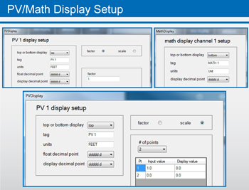
For PV Display Setup parameters, click the Setup button next to the desired PV. Within the resulting pop-up window, the user selects the desired settings from drop-down menus for Top or Bottom Display (Top, Bottom, or Off), Float Decimal Point (1 to five places or none), and Display Decimal Point (1 to five places or none). The user enters the Tag and Units in the appropriate boxes. The user chooses either Factor (for K-Factor) or Scale (For up to 32 Points). For Scale, select the number of points from the drop-down menu and enter the subsequent Input Values and Display Values accordingly. For Factor, simply enter the conversion factor in the box. CSV files can be imported/exported from the Setup window.
Math Display Setup parameters mostly follow the same conventions as the PV Setup, with drop-down menus for Top or Bottom Display (Top, Bottom, or Off), Float Decimal Point (1 to five places or none), and Display Decimal Point (1 to five places or none). The user enters the Tag and Units in the appropriate boxes. See the PV/Math Display Setup graphic below.
For Tank Size Indicator, simply enter the tank height in feet for the Max Reading (For programming Feet & Inches Scanners only).
Rate/Totalizer Screen
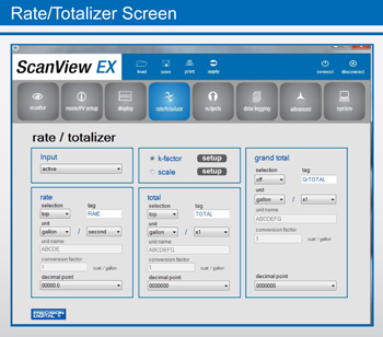
The Pulse Output Screen has five separate sections: Input, Rate, K-Factor/Scale, Total, and Grand Total.
For Input, the user chooses from the drop-down menu one of the following: Active, NPN, PNP, Reed, Coil, Isolated Active, Active with Low Threshold, NPN with Low Threshold, PNP with Low Threshold, or Disable.
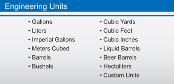
For Rate, Total, and Grand Total, the user begins by selecting Top, Bottom, or Off from the Selection drop-down menu. Select an engineering unit (See the graphic below) and a decimal point, plus either a time base or a multiplier {x1, x100(h), x1000(k), x1e6(M)} from the drop-down menus. Enter the Unit Names and Conversion Factors in the appropriate boxes.
For K-Factor or Scale, select one by clicking the button to the left of the selection, then clicking the selection's Setup button.
For K-Factor, simply select an engineering unit from the drop-down menu and enter the K-Factor value associated with the device you are connecting to (this information should be provided by the device's manufacturer).
For Scale setup, select an engineering unit from the Scale Unit drop-down menu. Select the number of points and a time base from the appropriate drop-down menus. In the table below the drop-down menus, the user then enters both the Input Value and the Display Value for each linearization point. Once the information has been entered by the operator, click Save to return to the Rate/Totalizer window.
Note: The operator can choose either k-factor or scale, but not both.
Outputs Screen
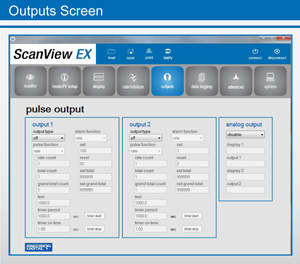
The Pulse Output Screen has two separate sections for controlling the meter's two NPN open collector outputs, Output 1 and Output 2. The category criteria for each output is identical. There is also a section for programming the scanner's analog output.
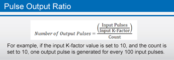
Pulse outputs are based on rate, total or grand total counts, or one-for-one retransmit for input pulses, as seen in the graphic below. Both outputs may be used to generate a quadrature output based on any pulse menu output type, though only one output should be set to quadrature. An output test mode is also selectable to generate pulses at a constant programmable frequency.
Alarms are available based on the rate, total, or grand total. The alarm status will show on the display even if the output is not wired. The outputs may also be forced on or off.
A timed pulse output (Timer) generates constant pulses at a specified frequency and on time. The output may be disabled by selecting Off.
Output type is selectable from a drop-down menu and can be set to off, pulse, alarm, or timer. Depending upon the selection, various drop-down menus and information fields become available to the operator. Each can be customized by the user to fit the proper application. Fields include: alarm function, pulse function, rate count, total count, grand total count, set, reset, set total, test, set grand total, timer period, & on time.
Pulse Function & Alarm Function have drop-down menus. Pulse Functions include rate, total, grand total, test, quadrature, or retransmit, plus PVs and Math Channels. Alarm Functions include rate, total, grand total, alarm on, or alarm off, plus PVs and Math Channels.
The Analog Output can be scaled for rate, total, or grand total, plus PVs and Math Channels. The output can also be disabled.
Data Logging Screen
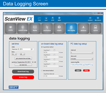
The Data Logging Screen is used to setup and enable the data log functions for both the On-Board and PC Data Log Setups. The scanner may contain up to 1024 records, each containing date, time, rate, total, grand total, and log number.
There are two ways to configure the time when a data log is recorded. The Log Set Time Method allows up to 4 data logs to be recorded each day, at specific times. The Time Interval Method allows a data log to be recorded when a time interval has passed.
Only the Log Set Time Method or Time Interval Method may be active at once. While one type of data logging has been enabled, the other menu will be inaccessible.
Log Set Time Method
The Log Time menu contains four log points (Log Time 1 to Log Time 4). Each log time is configured separately. For each daily log time desired, enable a log by checking its box, and set the log time for the hours and minutes the log is to be recorded. The time is set in real-time, based on the real time clock setup.
The Log Time feature will roll-over, deleting the oldest data logs (in blocks of 8) when the log is full and new logs must be recorded. This makes it the most useful for long-term data logging.
Time Interval Method
The Interval menu sets the time interval for data logging. Every time interval, one data point will be recorded. To enable interval data logging, enable the feature by checking its button, and set the interval time for the hours and minutes between each log. The Time Interval Method will not delete old data, and data logging will stop when the log is full. This makes it the most useful for short periods and logging specific functions. The Time Interval Method cannot be used if the data log is full.
For PC Data Log Setup, simply select an interval (1-59) and a time unit (minute, hour, or second), name the log file (optional), and use the buttons located below the log file name to start or stop the data logging process. Data Logs can be downloaded or erased using the buttons located in the lower left portion of the Data Logging screen.
Advanced Screen
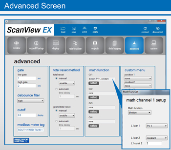
The Advanced Screen is divided into seven sections: gate, debounce filter, cutoff, Modbus scanner tag, total reset method, math function, and custom menu. The gate function is used for displaying slow pulse rates. Using the programmable gate, the scanner is able to display pulse rates as slow as 1 pulse every 9,999 seconds (0.0001 Hz). The gate function can also be used to obtain a steady display reading with a fluctuating input signal. There are two settings for the Gate, low gate and high gate.
For most applications, low gate setting should be left at 1 second. Increase low gate setting to obtain a steadier rate display. The rate display will update in accordance with the low gate setting, for example if low gate is set at 10, the display will update every 10 seconds; changes in rate between updates will not be reflected until next display update. Set the high gate value to correspond to the highest expected pulse period (lowest pulse rate). For instance if the scanner must display a rate when there is 1 pulse coming into the scanner every 10 seconds, set the high gate to 11 seconds. When the signal is removed from the scanner, the display will show the last reading for 11 seconds; then it will read zero.
The debounce filter function can be used for applications where the scanner is set up to count pulses generated by switch contacts. There are three settings, high, medium, and low. High disables the contact debounce filter and allows any pulse of the minimum specified width for the selected input type. The medium filter ignores signals faster than 250 Hz max, or pulse widths less than 2 ms at 50% duty cycle. The low filter ignores signals higher than 100 Hz, or pulse widths less than 5 ms at 50% duty cycle.
The low-flow cutoff feature allows the scanner to be programmed so that the often-unsteady output from a transmitter, at low flow rates, always displays zero on the meter. The cutoff value may be programmed from 0 to 9999.9. Below the cutoff value, the meter will display zero. Programming the cutoff value to zero disables the cutoff feature.
The Math Functions are selected using drop-down menus. Select for each channel the desired equation and its parameters, then click save. An example of the Math Function Setup can be seen above in the Advanced Screen inset.
There are both manual and automatic settings for the total reset and grand total reset. For manual reset, select whether manual reset will be enabled or disabled. Disabling reset will avoid inadvertent resets of the total/grand total via the front reset button or external reset contact.
For automatic reset, enter reset delay time in seconds. Once the output alarm total/grand total set point is reached, the scanner waits for a programmed amount of time and then resets the total/grand total to zero.
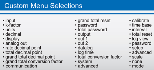
The custom menu section allows the operator to select from a list of choices to cutomize the scanner's menu for specific applications. There are up to eight different positions to choose from; see the graphic below for a full list of selections for each position. The Advanced Screen also features a Modbus meter tag for use in a Modbus network.
System Screen
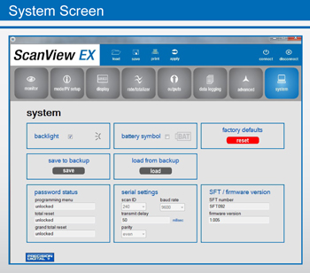
The System Screen allows the operator to enable the scanner's backlight, as well as the Battery symbol on the scanner's display. Settings can be both saved to and loaded from a backup, or restored to factory defaults.
The password status of the scanner can be obtained for the programming menu, the total reset, and grand total reset. Also available is information about the scanner's software and firmware versions. The scanner's Modbus Scan ID may also be set here.
The other serial settings, which are clearly visible, must match those of other devices on a Modbus network in order to avoid any breaks in communication. Changing serial settings may require the software serial settings to be changed in order to reconnect to the scanner.
Additional Information
About the Software
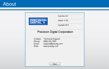
By clicking on the About button in the initial ScanView EX setup window, a popup window will appear displaying the version of ScanView EX installed. Also appearing in the window is both general and technical support contact information for Precision Digital Corporation.
Precision Digital Adapter & Converters
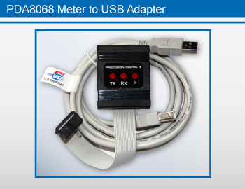
For quick and easy configuration of your PD6730X or PD6830X, use the PDA8068 Meter-to-USB adapter, which will work with all models of the scanners.
Use the PDA7485-N or PDA7485-I RS-232 to RS-485 converter for an RS-232 connection; or use the PDA8485-N or PDA8485-I USB to RS-485 converter for a USB connection.
PDA8068 comes with a USB cable. PDA7485 does not come with an RS-232 cable; a standard RS-232 cable may be used.
PDA8485 does not come with a USB cable; a standard USB cable may be used.
Load or Save Any Configuration
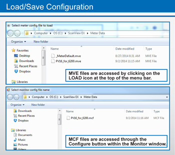
Monitor view configurations may be saved as ".mcf" files, and scanner parameter settings saved as ".mve" files. These can be loaded at any time from the ScanView EX folder on the computer's C: Drive:
C:\PDC\ScanView EX 1.00\Meter Data
"MVE" files are accessed by clicking on the LOAD icon at the top of the menu bar. "MCF" files are accessed through the Configure button within the Monitor window.
To create configuration files, load the default configuration file, change the settings, then save as a new configuration file.
Specifications
System Requirements: Windows® 2000/XP/Vista/7/8 (Windows 32-bit or 64-bit operating systems).
Communications: All models: PDA8068 Meter-to-USB adapter,
RS-232 to RS-485 converter, or USB to RS-485 converter.
PDA8068 comes with a USB cable.
PDA7485 does not come with an RS-232 cable; a standard RS-232 cable may be used.
PDA8485 does not come with a USB cable; a standard USB cable may be used.
Scanner Address: 1-247
Configuration: Save as ".mcf" (for Monitor Configuration) or ".mve" (for Scanner Configuration) file format or print configuration
Baud Rate: 1200 bps to 115,200 bps
Configuration: Configure scanner settings one scanner at a time.
Data Logging Report: Save as CSV file format.
Protocol: Modbus RTU
The Information contained in this document is subject to change without notice. Precision Digital Corporation makes no representations or warranties with respect to the contents hereof, and specifically disclaims any implied warranties of merchantability or fitness for a particular purpose.