

Features
- Wireless Repeater Unit Improves Signal Strength and Range for PDW Wireless Systems
- Use in PDW30 Point to Point and PDW90 Point to Multi-Point Wireless Systems
- Increase Range an Additional 1 Mile Line-of-Sight, 500 Feet Indoor
- Increases Range of the Analog, Digital I/O and Modbus Signals
- Simple to Configure Using PDW Manager Programming Software and On-Board USB
- Use CapTouch Through-Glass Buttons to Change Network ID
- Device Communication Secured by Enabling 128-bit AES Encryption
- Password Protection
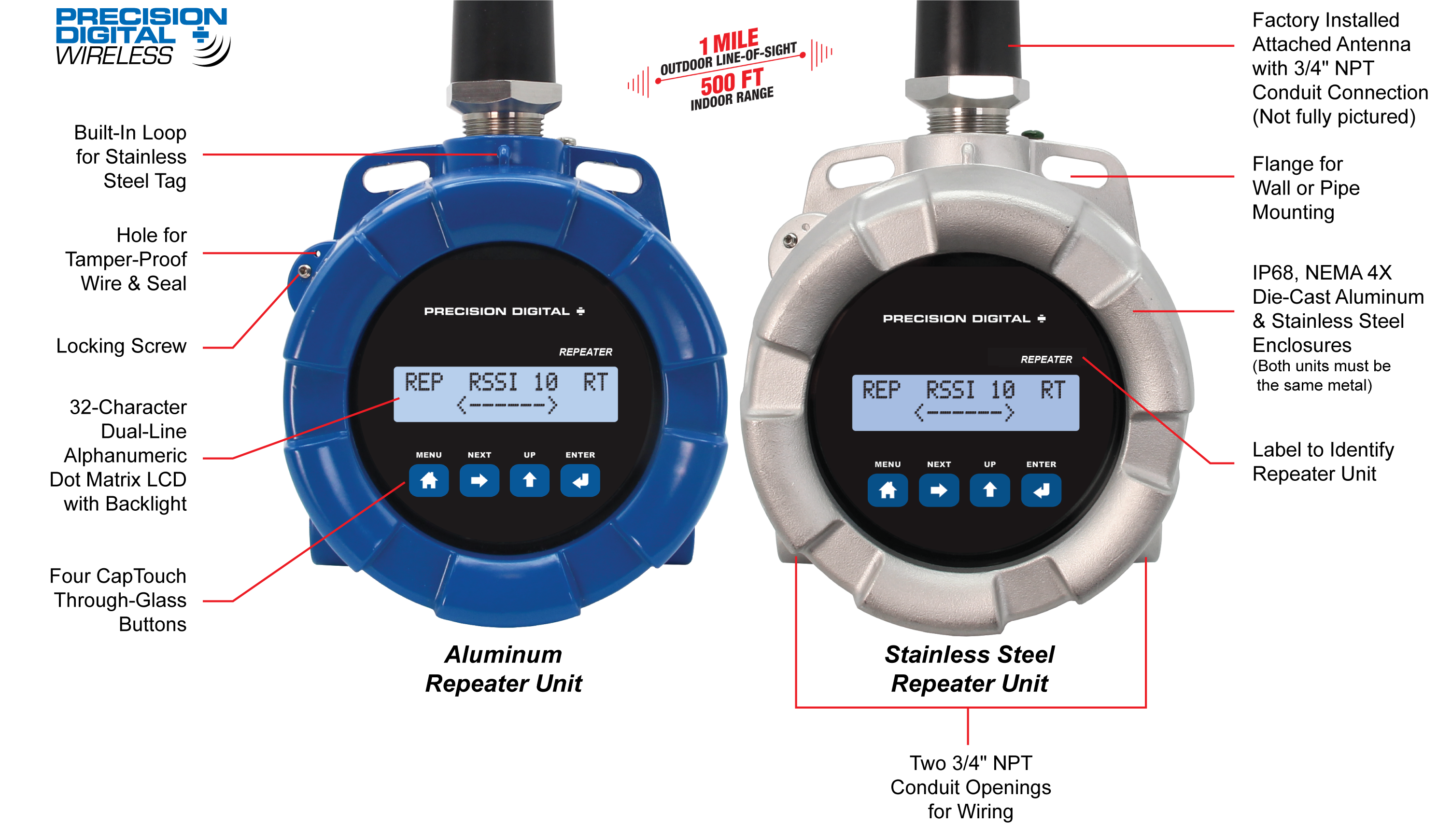
- IP68, NEMA 4X Aluminum & Stainless Steel Enclosures With Plenty of Room for Field Wiring
- Operating Temperature Range: -55 to 75°C (-67 to 167°F)
- Conformal Coated PCBs for Dust & Humidity Protection
- Flange for Wall or Pipe Mounting; Loop for Stainless Steel Tag; Holes for Tamper-Proof Seal
- 9-30 VDC Power
- 3-Year Warranty
Overview
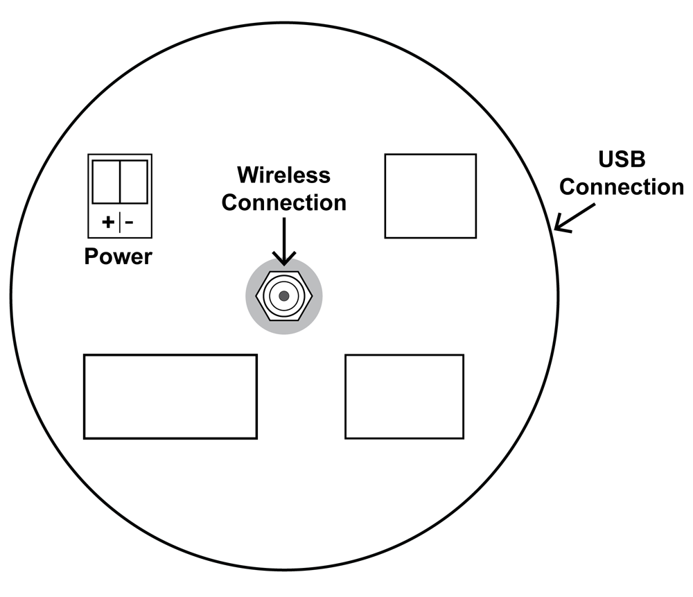
Connections
Extend the Signal Range of PDW30 and PDW90 Wireless Systems with PDWR Wireless Signal Repeaters
PDWR wireless signal repeaters are used to improve the connectivity in PDW30 point to point and PDW90 point to multi-point wireless systems. They will generally increase signal range of the system by another 1 mile line-of-sight or 500 feet indoor.
The repeaters are simple to install as they only require power and a network ID. Any PDW wireless units in range of the repeater with the same network ID will retransmit through it, thus increasing signal strength.
PDWR repeaters can be used to broadcast over very long distances or around permanent obstacles.
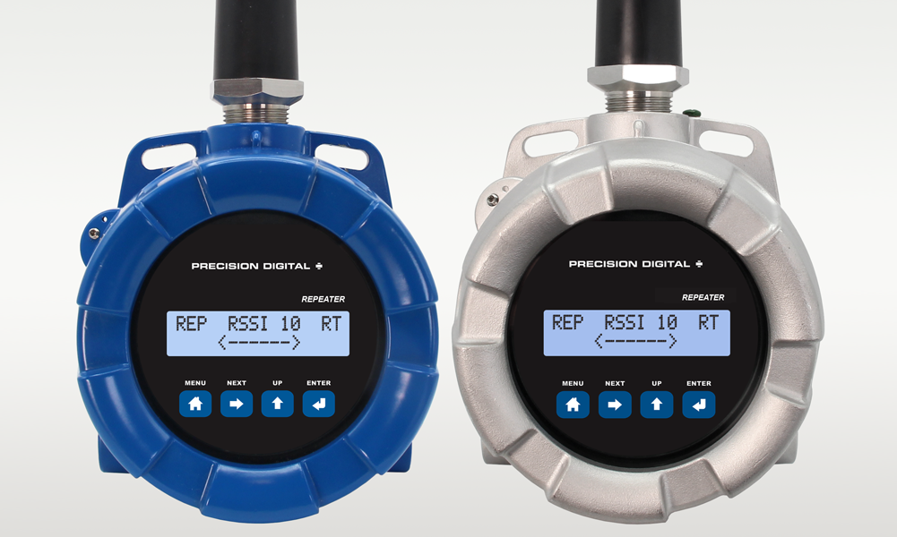
The PDWR repeaters are available in either aluminum or stainless steel NEMA 4X, IP68 enclosures and these enclosures contain plenty of room for field wiring connections.
Key Features
PDW Manager PC Programming Software
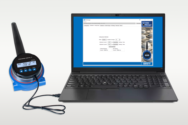
PDW Manager PC Software allows for programming the PDWR repeater units from a PC with a USB connection. The units connect to a PC via the USB connection on the side of the display module behind the cover of the enclosure.
Use of PDW Manager is required for programming advanced settings such as wireless encryption. PDW Manager is available for download at www.predig.com/pdwmanager.
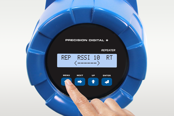
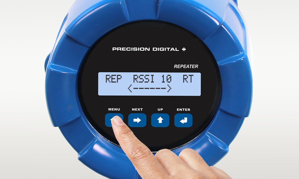
CapTouch Through-Glass Buttons
The PDWR repeater units are equipped with four capacitive sensors that operate as through-glass buttons so that they can be operated without removing the cover (and exposing the electronics) in an unclean area.
CapTouch buttons allow the Network ID to be pro-grammed without removing the cover.
CapTouch buttons are designed to work under any lighting condition and are not affected by random changes in light or shadows. To protect against false triggering a long button press of about 2 seconds is required to wake up the buttons when they have not been in use.
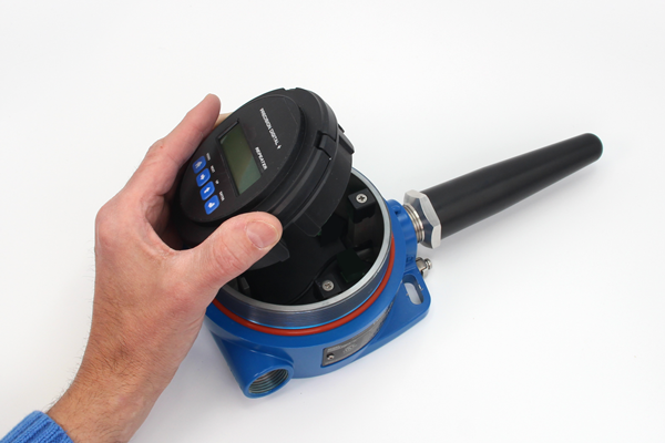
Easy-To-Install Display Module
The display module designed specifically for the PDWR wireless units are easy to remove making it convenient for wiring the unit. The display module is completely enclosed for added protection when wiring and handling.
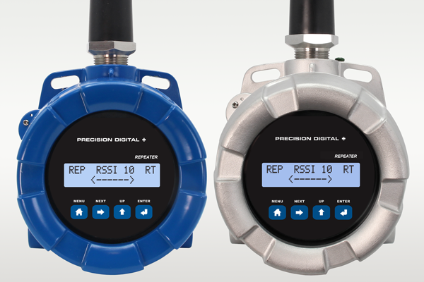
Repeater Units Available in Aluminum or Stainless Steel
The PDWR repeater units are available in an IP68, NEMA 4X aluminum or stainless steel enclosure. The enclosures feature a built-in flange for wall or pipe mounting, built-in loop for a stainless steel tag, locking screw, and hole for a tamper-proof wire & seal. The enclosure also includes two 3/4" threaded conduit openings for wiring. The PDWR repeater units can operate in temperatures of -55 to 75°C (-67 to 167°F).
Application Example
Extending Signal Range with PDWR Repeaters
The PDWR repeaters are used to retransmit wireless signals when connectivity between the PDW30 primary and secondary units or the PDW90 base station and field units are out of range or are obstructed by other objects or structures.
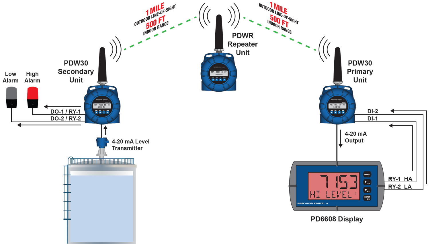
PDW30 Point-to-Point Wireless Bridge Using a Repeater to Extend the Signal Range
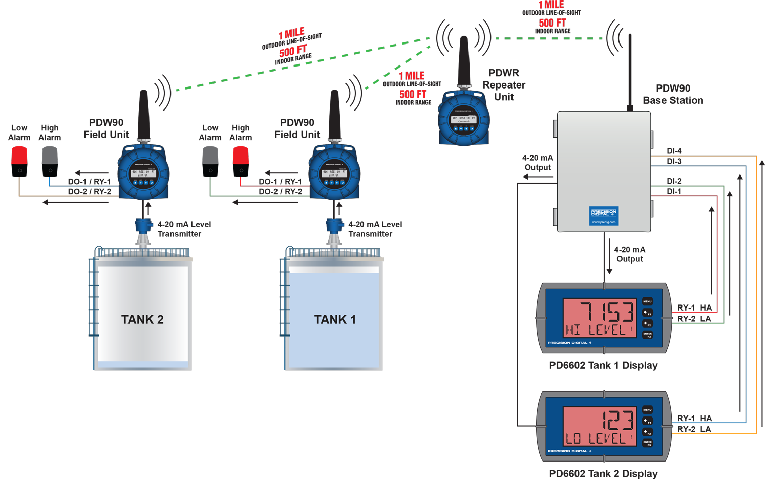
PDW90 Point to Multi-Point Wireless System Using a Repeater to Extend the Signal Range


 Enclosure Dimensions - Top View
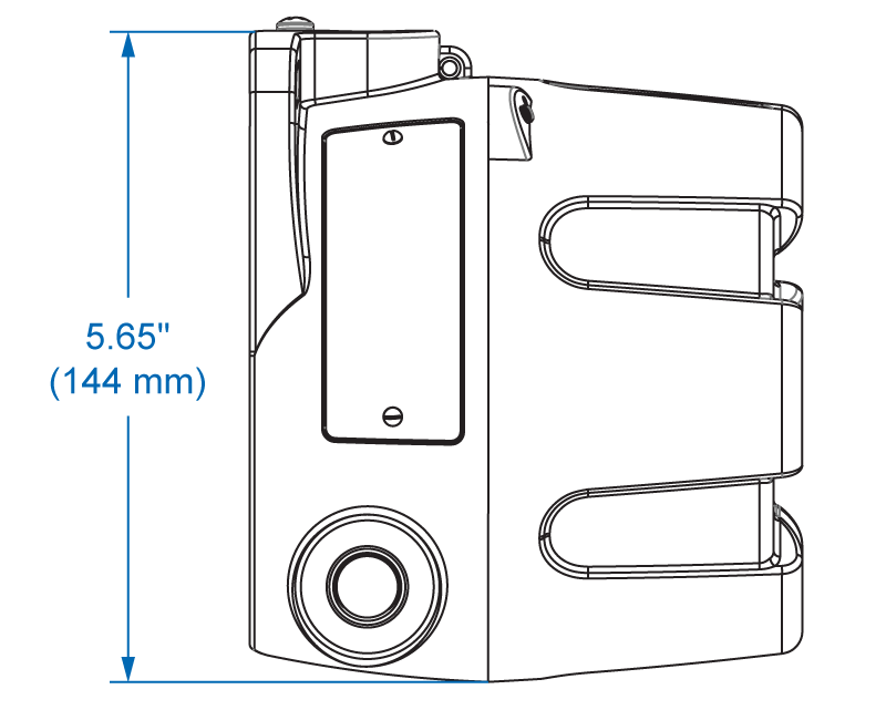 Enclosure Dimensions - Side View