General
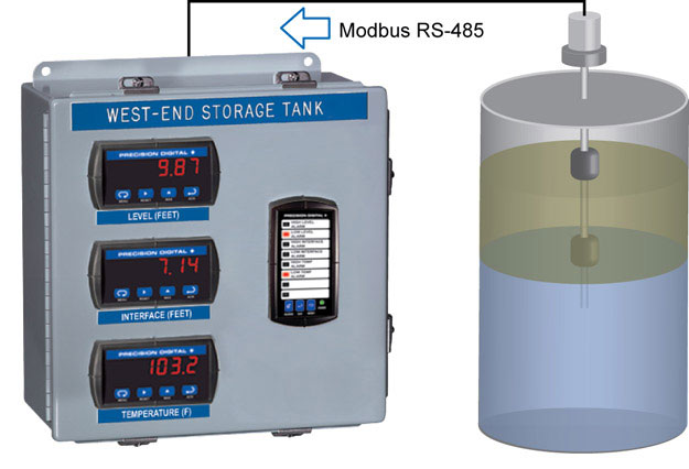
Input/Output: Modbus RTU RS-485
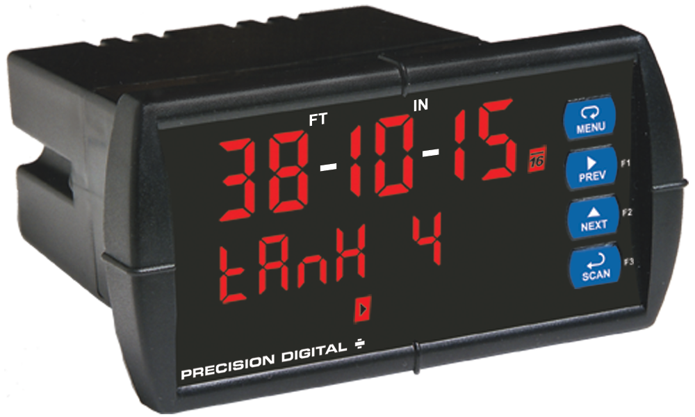
Display: 0.56" (14.2 mm) red LED, 6 digits; displays from -199999 to 999999, automatic leading zero blanking
Display Intensity: Eight user selectable intensity levels
Display Decimal Point: Up to five decimal places: d.ddddd, dd.dddd, ddd.ddd, dddd.dd, ddddd.d, or dddddd
Float Decimal Point: Select the number of decimals to use for the floating point data expected from the slave or master device
Front Panel: NEMA 4X, IP65; panel gasket provided
Programming Methods: Four front panel buttons or via Modbus registers (Slave mode only)
Scaling: Input may be scaled from -199,999 to 999,999
Math Functions: Linear, square root, or programmable exponent from 0.50000 to 2.99999
Multi-Point Linearization: 2 to 16 points
Noise Filter: Programmable 2 to 199 (0 will disable filter)
Bypass: 0.2 to 99.9% of full-scale
Cutoff: 0 to 999999; 0 disables cutoff
Display Update Rate: Master: 10/sec to 1 every 25.5 seconds;
Slave and Snooper: Dependent on master device (PLC, DCS, RTU, etc)
Overrange: Display flashes 999999
Underrange: Display flashes -199999
Max/Min Display: Stored until reset by user or meter is turned off; user can reset by front panel buttons or via Modbus registers.
Password: Restricts modification of programmed settings.
Non-Volatile Memory: Settings stored for a minimum of 10 years.
Power Options: 85-265 VAC, 50/60 Hz; 90-265 VDC, 20 W max or 12-36 VDC; 12-24 VAC, 6 W max.
Required Fuse: UL Recognized, 5 A max, slow-blow; up to 6 meters may share one fuse.
Normal Mode Rejection: 64 dB at 50/60 Hz
Transmitter Supply: Isolated 24 VDC ±10% @ 200 mA max
Isolation: 4 kV input/output-to-power line, 500 V input-to-output or output-to-24 VDC supply
Operating Temperature: -40 to 65°C
Storage Temperature: -40 to 85°C
Relative Humidity: 0 to 90% non-condensing
Connections: Removable screw terminals accept 12 to 22 AWG
Enclosure: 1/8 DIN, high impact plastic, UL 94V-0, color: gray
Weight: 9.7 oz (275 g) (including options)
UL File Number: E160849; 508 Industrial Control Equipment
Warranty: 3 years parts & labor
Operating Modes
Master: Processes data read from a Modbus RTU slave device (only one process variable at a time can be displayed on the master).
Master Proxy Polling: Polls up to 8 process variables up to 8 slave devices. The Master processes and displays one PV and allows other PD865s in Snooper mode to read any of the variables being polled.
Snooper: Listens to the Modbus traffic and picks up a specific process variable being polled by a Master device from a specific slave device and processes the data being read.
Slave: Processes data sent from a Modbus RTU master device.
Note that the relays and the 4-20 mA output are functional in all modes.
Master and Snooper Modes Settings
Function Code: Modbus function code 03 or 04.
Number of PVs: Number of process variables to be polled (PV1-PV8)
Slave ID: Address (1-247) of up to 8 slave devices
Register Number: 1 to 65536. Specifies which register(s) to read in the slave device. Register number is preceded by register type (3xxxxx or 4xxxxx). Five or six digit register number allowed.
Data Type: Select the data format that the slave device uses; select between Short (2 byte) and Long (4 byte) Integers or Floating point (4 byte), Signed or Unsigned (integer only), and byte order (big-endian vs little-endian).
Slave Response Timeout: 0 to 25.4 seconds.This is the time allowed for slave to respond to a command. 0 disables timeout (Master Mode Only)
Poll Time: 0.1 to 25.5 seconds between read commands
Relays
Rating: 2 Form A (SPST) standard; 2 Form C (SPDT) optional; rated 3 A @ 30 VDC or 3 A @ 250 VAC, resistive loads; 1/14 HP @ 125/250 VAC inductive loads
High or Low Alarm: User may program any alarm for high or low
Deadband: 0-100% FS, user selectable
Relay Operation:
1. Automatic (non-latching)
2. Latching
3. Pump alternation control (up to 4 relays)
Relay Reset: Selectable via front panel or Modbus registers
1. Automatic reset only (non-latching)
2. Automatic plus manual reset at any time (non-latching)
3. Manual reset only, at any time (latching)
4. Manual reset only after alarm condition has cleared (latching)
Automatic Reset: Relays reset when input passes the reset point
Manual Reset: Front panel button, Modbus registers (Slave only)
Time Delay: 0 to 199 seconds, on and off delays, programmable and independent for each relay
Fail-Safe Operation: Programmable, independent for each relay
Communications Break: No change, Relay on, or Relay off. Controls the condition the relay goes to when a slave device does not reply (Master and Snooper modes).
Auto Initialization: When power is applied to the meter, relays will reflect the state of the input to the meter
Serial Communications
Compatibility: EIA-485 (RS-485)
Protocol: Modbus RTU
Slave ID or Address: 1 to 247. Specifies the ID or address of the slave device (Master and Snooper modes) or the address of the PD865 (Slave mode).
Baud Rate: 300 to 19,200 bps
Data: 8 bits (1 start bit, 1 stop bit; 1 or 2 stop bits with no parity)
Parity: None, even, or odd
Byte-to-Byte Timeout: 0.01 to 2.54 seconds
Turn Around Delay: Less than 2 ms (fixed)
Isolated 4-20 mA Transmitter Output
Scaling Range: 1.000 to 23.000 mA; reverse scaling allowed.
Calibration: Factory calibrated 4.000 to 20.000 mA
Accuracy: ±0.1% FS ±0.004 mA
Recalibration: Recommended at least every 12 months.
Temperature Drift: 50 PPM/°C
Transmitter Supply: Isolated 24 VDC ±10% @ 200 mA max
Isolation: 500 V input-to-output or output-to-24 VDC supply; 4 kV output-to-power line
External Loop Power Supply: 35 VDC maximum
Output Loop Resistance:
| | Loop Resistance |
| Power Supply | Minimum | Maximum |
| 24 VDC | 10 Ω | 700 Ω |
| 35 VDC (external) | 100 Ω 1200 Ω | |
Data Source: Display value, maximum display value, minimum display value, or Modbus register
Overrange: Programmable mA output for overrange condition
Underrange: Programmable mA output for underrange condition
Communications Break: Programmable mA output when a slave device does not reply within the Slave Response Timeout
Maximum Output: Programmable absolute maximum mA output
Minimum Output: Programmable absolute minimum mA output