Except where noted all specifications apply to operation at +25°C.
General
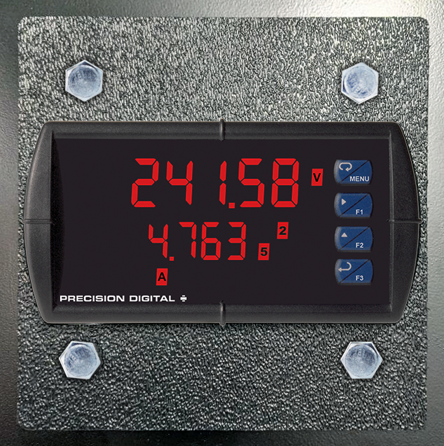
Display: Line 1: 0.60" (15 mm) high, red LEDs Line 2: 0.46" (12 mm) high, red LEDs 6 digits each (-99999 to 999999), with lead zero blanking
Display Intensity: Eight user selectable intensity levels.
Default is six.
Display Update Rate: 5/second (200 ms)
Overrange: Display flashes 999999
Underrange: Display flashes -99999
Display Assignment: Either display line may be assigned to the voltage (channel V) or mV (Channel A) input
Programming Methods: Four front panel buttons, digital inputs, PC and MeterView Pro software, or Modbus registers.
Noise Filter: Programmable from 2 to 199 (0 will disable filter)
Filter Bypass: Programmable from 0.1 to 99.9% of calibrated span
Recalibration: All ranges are calibrated at the factory. Recalibration is recommended at least every 12 months.
Max/Min Display: Max/min readings reached by each displayed input type are stored until reset by the user or until power to the meter is cycled.
Rounding: Select 1, 2, 5, 10, 20, 50, or 100 (e.g. rounding = 10, value = 123.45, display = 123.50).
Password: Three programmable passwords restrict modification of programmed settings.
Pass 1: Allows use of function keys and digital inputs
Pass 2: Allows use of function keys, digital inputs and editing set/reset points
Pass 3: Restricts all programming, function keys, and digital inputs.
Non-Volatile Memory: All programmed settings are stored in non-volatile memory for a minimum of ten years if power is lost.
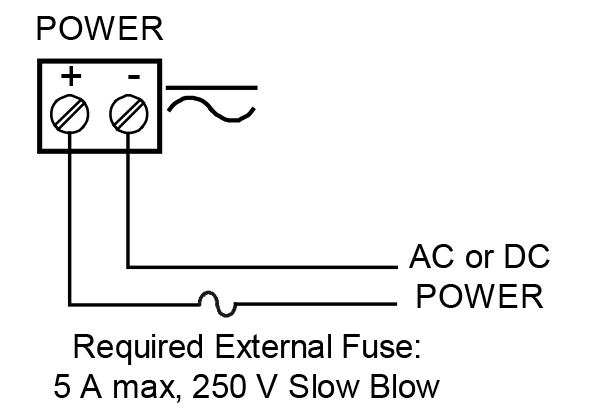
Power Options: 85-265 VAC 50/60 Hz; 90-265 VDC, 20 W max; 12-24 VDC, 12-24 VAC, 15 W max. Powered over USB for configuration only.
Fuse: Required external fuse: UL Recognized, 5 A max, slow blow; up to 6 meters may share one 5 A fuse
Isolation: 500 V AC/DC potential allowed between voltage and current input channels. Channels isolated by 3 MΩ impedance 4 kV input/output-to-power line 500 V input-to-output or output-to-P+ supply
Overvoltage Category: Installation Overvoltage Category II: Local level with smaller transient overvoltages than Installation Overvoltage Category III.
Environmental: Operating temperature range: -40 to 65°C (-40 to 149°F)
Storage temperature range: -40 to 85°C (-40 to 185°F)
Relative humidity: 0 to 90% non-condensing
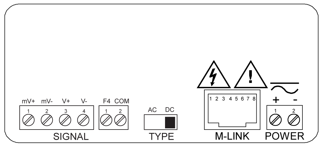
Connections: Removable screw terminal blocks accept 12 to 22 AWG wire, RJ45 for external relays, digital I/O, and serial communication adapters.
Enclosure: 1/8 DIN, high impact plastic, UL 94V-0, color: black
Front Panel: NEMA 4X, IP65
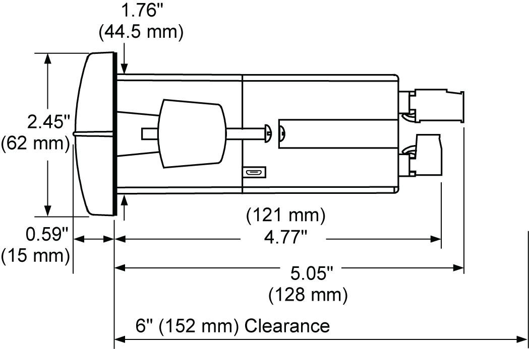
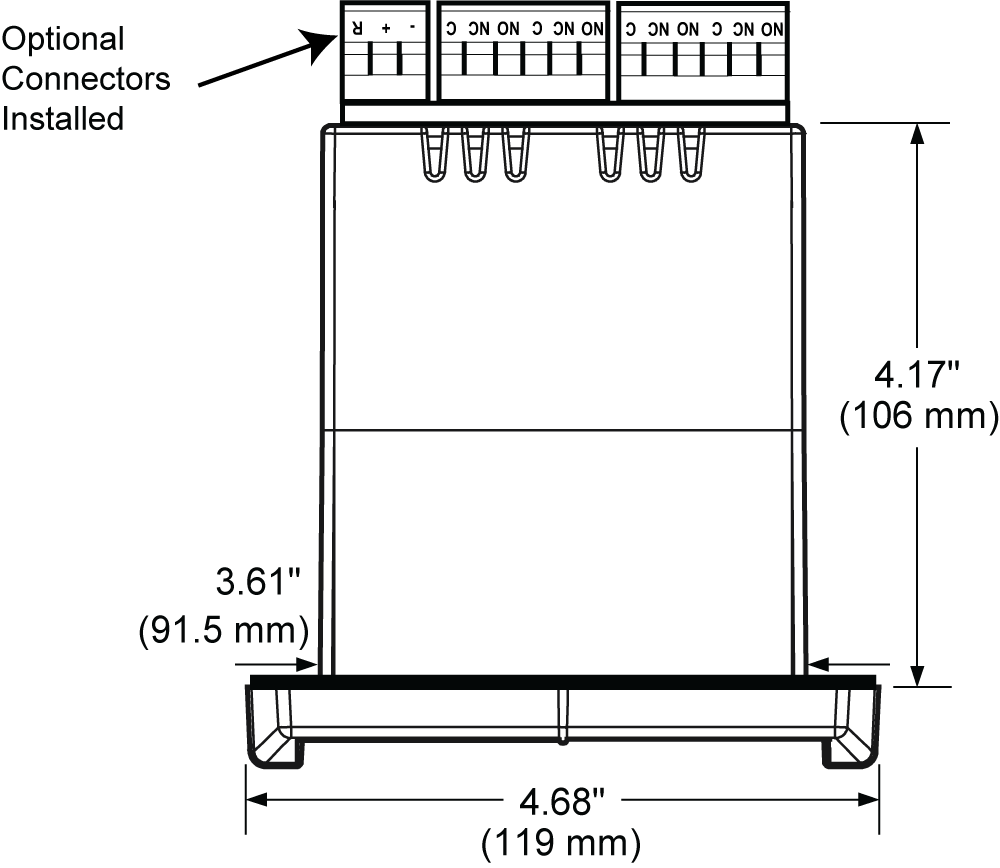
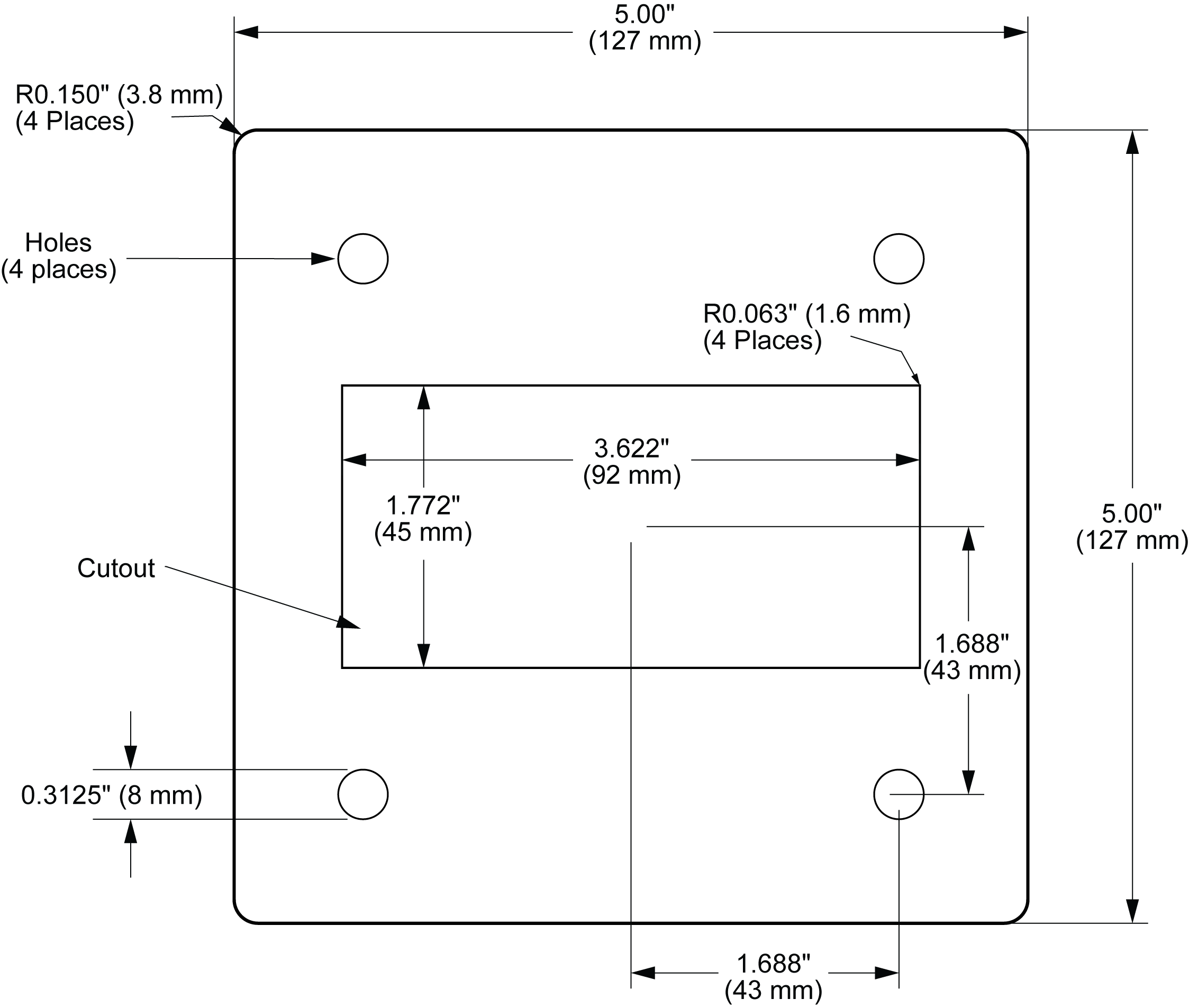
Mounting: 1/8 DIN panel cutout required: 3.622" x 1.772" (92 mm x 45 mm)
Two panel mounting bracket assemblies are provided.
Optional PDA6018 mounting plate available to accommodate existing Bitronics panel cutout.
Tightening Torque: Screw terminal connectors: 5 lb-in (0.56 Nm)
Overall Dimensions: 4.68" x 2.45" x 5.64" (119 mm x 62 mm x 143 mm) (W x H x D)
Weight: 9.5 oz (269 g)
Warranty: 3 years parts & labor. See Warranty Information and Terms & Conditions on www.predig.com for complete details.
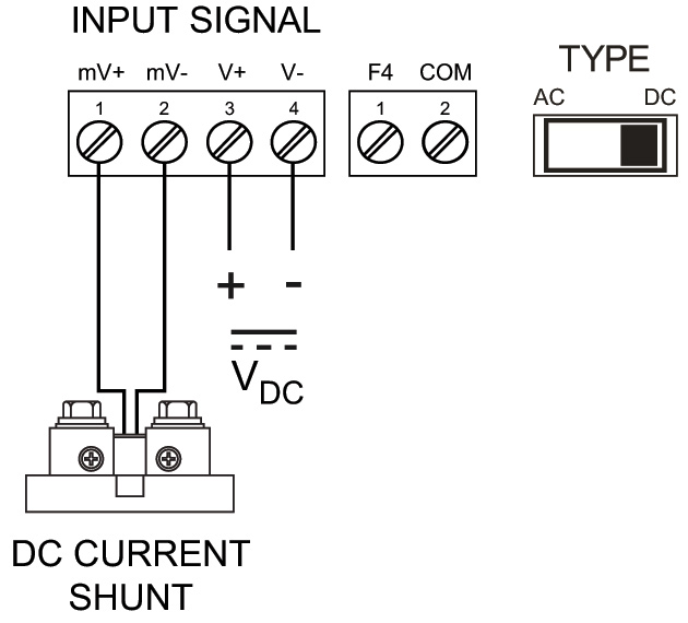
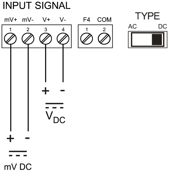
High Voltage & mV Inputs
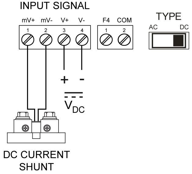
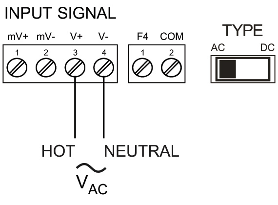
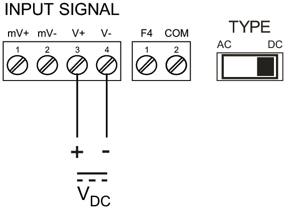
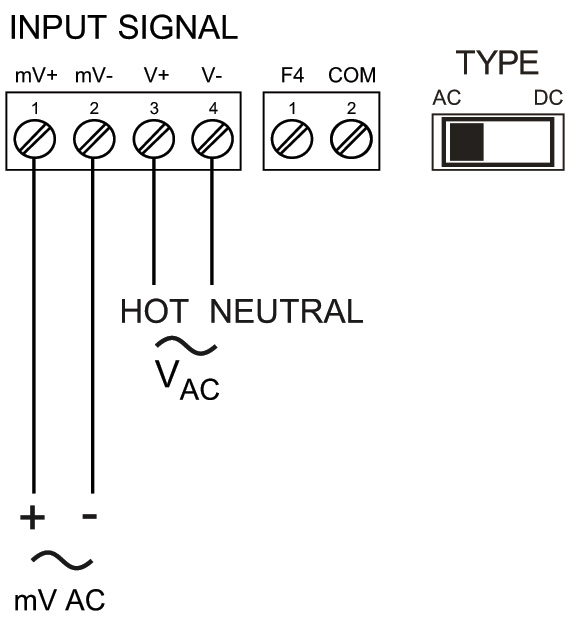
High Voltage Input: One high voltage input (Channel V) 0-300 VDC or VAC; Switch Selectable
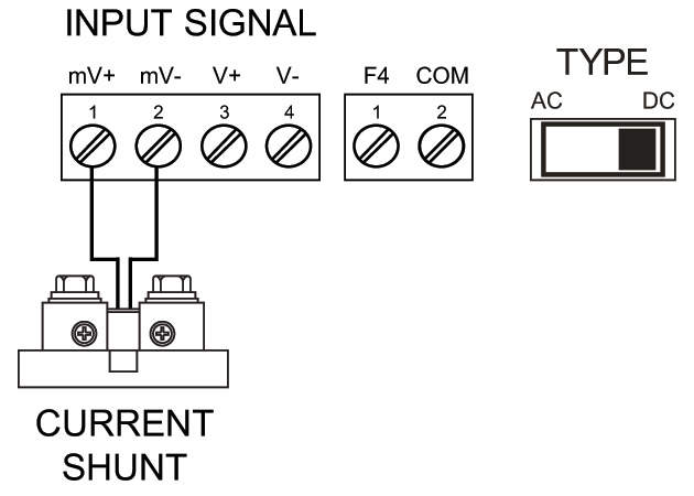
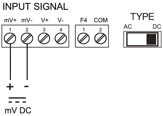
mV Input: One mV input (Channel A) 0-150 mV; Switch Selectable
Factory Default: 0-100 mV input corresponds to 0.000 to 0.100 display. User may scale for different ranges.
Crest Factor: 2 at full scale (Vp / Vrms)
AC Frequency: 30 to 400 Hz
Response Time: 5 seconds to rated accuracy
Channels: Channel A, Channel V, Channel P (Math Channel for Apparent Power)
AC/DC Selection: Switch selectable for AC or DC inputs. Channels A and V share AC/DC selection.
Apparent Power Math: Apparent power P calculated as P = ((A * V) + C) * F
Programmable Constants: Constant C (Adder): -99.999 to 999.999, default: 0.000
Constant F (Factor): 0.001 to 999.999, default: 1.000
Accuracy: mV DC: 0.03% Full Scale ±1 count,
mV AC: 0.1% Full Scale ±1 count,
VDC: 0.05% Full Scale ±1 count,
VAC: 0.15% Full Scale ±1 count
Temperature Drift: 0.005% of calibrated span/C max from -40 to 65C ambient
Multi-Point Linearization: 2 to 32 points for Channel A and V
Low-Value Cutoff: 0.1 to 999,999 (0 disables cutoff function). Point below at which the display always shows zero. Independent for Channel A and V.
Decimal Point: Up to five decimal places or none: d.ddddd, d.dddd, d.ddd, d.dd, d.d, or dddddd
Calibration Range:
| Input Channel | Input Range | Minimum Span Input 1 & Input 2 |
| A | ± 0-150 mV DC 0-150 mV AC | ± 0.5 mV DC 1 mV AC |
| V | ± 0-300 VDC 0-300 VAC | ± 0.1 VDC 0.3 VAC |
An error message will appear if the input 1 and input 2 signals are too close together.
Input Impedance: Voltage Input: 6 MΩ differential input
Current Input: 0.01 Ω
Display Resolution: 1 display count
Input Overload: Voltage input protected up to 500 VDC
mV current input protected up to 10 VDC
F4 Digital Input Contacts: 3.3 VDC on contact. Connect normally open contacts across F4 to COM.
F4 Digital Input Logic Levels: Logic High: 3 to 5 VDC
Logic Low: 0 to 1.25 VDC
Relays
Rating: 2 or 4 SPDT (Form C) internal and/or 4 SPST (Form A) external; rated 3 A @ 30 VDC and 125/250 VAC resistive load; 1/14 HP (≈ 50 W) @ 125/250 VAC for inductive loads
Noise Suppression: Noise suppression is recommended for each relay contact switching inductive loads; see manual for details.
Relay Assignment: Each relay independently assigned to Ch-A, Ch-V, CH-P, or Modbus input
Deadband: 0-100% of span, user programmable
High or Low Alarm: User may program any alarm for high or low trip point. Unused alarm LEDs and relays may be disabled (turn off).
Relay Operation:
- Automatic (non-latching) and/or manual reset
- Latching (requires manual acknowledge) with or without clear
- Pump alternation control (2-8 relays)
- Sampling (based on set point and time)
- Off (disable unused relays and enable Interlock feature)
- Manual on/off control mode
Relay Reset: User selectable via front panel button, F4 terminal at back of meter, external contact closure on digital inputs, or through serial communications.
- Automatic reset only (non-latching), when the input passes the reset point.
- Automatic + manual reset at any time (non-latching)
- Manual reset only, at any time (latching)
- Manual reset only after alarm condition has cleared (L)
Note: Front panel button, F4 terminal at back of meter or digital input may be assigned to acknowledge relays programmed for manual reset. Time Delay: 0 to 999.9 seconds, on & off relay time delays. Programmable and independent for each relay
Fail-Safe Operation: Programmable and independent for each relay.
Note: Relay coil is energized in non-alarm condition. In case of power failure, relay will go to alarm state. Break Condition Operation: Relay condition when sensor break detected. Programmable independently for each relay as On, Off, or Ignore (maintain last condition).
Auto Initialization: When power is applied to the meter, relays will reflect the state of the input to the meter.
Additional Relays: An external module, model PDA1004, is available to add 4 SPST 3 A relays to the meter.
Isolated 4-20 mA Transmitter Output
Output Source: Process channel A, V, or P, max or min for channel A, V, or highest or lowest max or min of A and V, set points 1-8, Modbus input, or manual control mode
Scaling Range: 1.000 to 23.000 mA for any display range
Calibration: Factory calibrated: 4.000 to 20.000 = 4-20 mA output
Analog Out Programming: 23.000 mA maximum for all parameters: Overrange, underrange, max, min, and break
Accuracy: ± 0.1% of span ± 0.004 mA
Temperature Drift: 0.4 μA/C max from 0 to 65C ambient, 0.8 μA/C max from -40 to 0C ambient
Note: Analog output drift is separate from input drift.
Isolated Transmitter Power Supply: Terminals I+ & R: 24 VDC 10% @ 40mA. May be used to power the 4-20 mA output or other devices.
All models rated @ 40 mA max.
External Loop Power Supply: 35 VDC maximum
Output Loop Resistance:
| Power supply | Minimum | Maximum |
| 24 VDC | 10 Ω | 700 Ω |
| 35 VDC | 100 Ω | 1200 Ω |
Additional 4-20 mA Outputs: The PD659-1MA-2MA can split the optional 4-20 mA output into two isolated 4-20 mA outputs
0-10 VDC Output: The PD659-1MA-1V can convert the optional 4-20 mA output to a 0-10 VDC output
USB Connection
Function: Programming only
Compatibility: USB 2.0 Standard, Compliant
Connector Type: Micro-B receptacle
Cable: USB A Male to Micro-B Cable
Driver: Microsoft® Windows® XP/Vista/7/8/10
Power: USB port provides power to the meter.
DO NOT apply AC or DC power to the meter while the USB port is in use.
On-Board Digital Input (F4)
Function: Remote operation of front-panel buttons, acknowledge/reset relays, reset max/min values.
See manual for a complete list of capabilities.
Contacts: 3.3 VDC on contact. Connect normally open contacts across F4 to COM
Logic Levels: Logic High: 3 to 5 VDC
Logic Low: 0 to 1.25 VDC
Additional I/O: Up to 2 external modules, model PDA1044 with 4 digital inputs and 4 digital outputs each can be added.
Modbus® RTU Serial Communications
Slave Id: 1 – 247 (Meter address)
Baud Rate: 300 – 19,200 bps
Transmit Time Delay: Programmable between 0 and 199 ms
Data: 8 bit (1 start bit, 1 or 2 stop bits)
Parity: Even, Odd, or None with 1 or 2 stop bits
Byte-To-Byte Timeout: 0.01 – 2.54 second
Turn Around Delay: Less than 2 ms (fixed)
Note: Refer to the PROVU Modbus Register Tables located at www.predig.com for details.
MeterView Pro
Availability: Download directly from meter or from www.predig.com/download_software
System Requirements: Microsoft® Windows® XP/Vista/7/8/10
Communications: USB 2.0 (for programming only) (Standard USB A to Micro USB B)
RS-232 adapter, RS-485 adapter and RS-485 to USB converter (programming, monitoring, and data logging)
Configuration: Configure meters one at a time
Power: USB port provides power to the meter.
DO NOT apply AC or DC power to the meter while the USB port is in use.