General
Decimal Display: Top Display: Five Digits (0 to 99999), 0.7" (17.8 mm) high, 7-segment, automatic lead zero blanking.
Bottom Display: Seven Characters, 0.4" (10.2 mm) high, 14-segment, automatic lead zero blanking.
Symbols: High alarm, low alarm, SafeTouch button sleep mode/disable, password lock.
Feet & Inches Display: Top Display: Feet & Inches, 0.60" (15.2 mm) high, 0 to 399FT, 11 15/16 IN, 7-segment, programmable 1/16 or 1/8 fraction display.
Bottom Display: Seven Characters, 0.4" (10.2 mm) high, 14-segment, 7-digits.
Tank Level Indicator: 20-segments, F (Full) and E (Empty)
Alarm Indication: High and low alarm
Backlight: White
Display Assignment: Top and Bottom Display*: Process Variables (PV); Alternating PV and Units, Tag and PV, or Tag, PV, and Units.
Bottom Display: All Top Display Options or Off
Units and tag independent for each PV.
*On feet and inches display models, top display used only for level Modbus process variables or math channels.
Backlight: White; it can be disabled/enabled in the Advanced - System menu. The backlight is automatically turned off below -20°C.
Alarm Indication: Flashing display plus HI/LO indicators
Scan and Update Rate: Ambient > -20°C: Modbus PV scan rate programmable from 2 to 99 seconds per PV. Tag and units programmable for 1 to 5 second alternation.
Ambient < -20°C: All Modbus scan, alternating units and tags 1 update/10 seconds minimum.
Underrange: Upper Display: Decimal display flashes -9999
Level display flashes to 399FT 11 15/16 IN
Lower Display: Flashes -999999
Overrange: Upper Display: Decimal display flashes 99999
Level display flashes to 399FT 11 15/16 IN
Lower Display: Flashes 9999999
Programming Method: Four SafeTouch through-glass buttons when cover is installed. Four internal push buttons when cover is removed. Free ScanView EX software.
Password: Restricts modifications of programmed settings to require re-entering the password to make changes.
Input Power: 9-30 VDC, 2.2 W
Data Logging: Up to 512 records, recorded 4/day at specific times or at defined time intervals. Record contains first eight enabled Modbus PVs; C1-4 if enabled; date, time, and log number.
Isolation: All Models: 500 V power-to-RS-485 serial communications
-AXA Models: 500 V power-to-analog output
Environmental: Operating temperature range: -40 to 75°C;
Storage temperature range: -40 to 75°C;
Backlight deactivated below temperatures ≈ -20°C;
Relative humidity: 0 to 90% non-condensing
Printed circuit boards are conformally coated.
Non-Volatile Memory: All programmed settings are stored in non-volatile memory for a minimum of ten years if power is lost.
Connections: Screw terminals accept 12 to 22 AWG wire
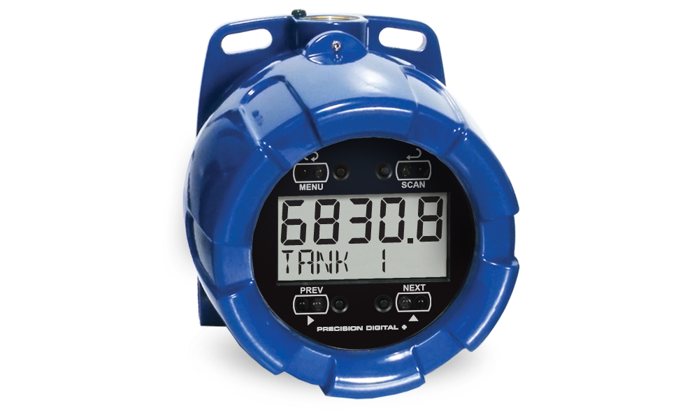
Enclosure: Explosion-proof die-cast aluminum with glass window, corrosion resistant epoxy coating, copper-free (0.3%)
Color: blue.
NEMA 4X, 7, & 9, IP68.
Conduit connections:
Three ¾" NPT threaded conduit openings.
One ¾" NPT metal plug with 12 mm hex key fitting installed.
Additional conduit opening configurations and plugs may be available; verify quantity and sizes on specific device labeling during installation.
Mounting: May be mounted directly to conduit. Two slotted flanges for wall mounting or NPS 1½" to 2½" or DN 40 to 65 mm pipe mounting.
Display Orientation: Display may be mounted at 90° increments up to 270° from default orientation.
Overall Dimensions: 5.67" x 5.24" x 4.88" (W x H x D) (144 mm x 133 mm x 124 mm)
Weight: 5.00 lbs (80 oz, 2.27 kg)
Warranty: 3 years parts and labor. See
Warranty Information and Terms & Conditions for complete details.
Modbus Operating Modes
Master: Processes and displays data read from Modbus RTU slave devices. Up to 16 process variables (PVs) from up to 16 slave devices. Each PV programmed individually.
Slave: Processes data sent to it from a Modbus RTU master device.
Note: Refer to Modbus Register Tables for details.Snooper: Listens to the Modbus traffic and picks up a specific register or registers being polled by a Master device from a specific slave device and processes the data being read. Up to 16 process variables (PVs) from up to 16 devices. If multiple registers are polled by the master with one command, only the first returned value will be read.
Master Poll Time: 0.1 to 99.9 sec. Time between read-commands.
Master Timeout: 0.1 to 99.9 seconds. Time elapsed after a poll request is made before the scanner considers that request to have failed.
Number of Retries: 1-99. The number of retries the scanner will make when requesting data before reporting an error condition on the PV.
Snooper Response Time: 0.1 to 99.9 seconds. Time since the last PV update the before being considered an error.
Slave Timeout: 0.0 to 99.9 seconds. Time elapsed after the last data received from a master before the scanner considers the data to be out of date. Programming 0 disables the timeout, and PV data will be displayed indefinitely despite not being updated regularly.
Serial Communications
Protocol: Modbus® RTU
Scanner ID: 1 – 247. Specifies the address of the PD6830X.
Baud Rate: 1,200; 4,800; 9,600; 19,200; 38,400; 57,600; or 115,200 bps
Transmit Time Delay: Programmable between 0 and 199 ms
Parity/Stop Bit: Even, odd, none with 1 stop bit, or none with 2 stop bits
Byte-to-Byte Timeout: Max of 1.5 character times or 750 μs
Note: Refer to Modbus Register Tables at www.predig.com for details.Modbus Scanner Process Variables
PV Inputs: Up to 16 independently programmed Modbus process variables (PVs) may be scanned (Master mode) or detected (Snooper mode). Each of the 16 Modbus PVs may be enabled or disabled.
Slave ID: Specifies which device on the bus to monitor. Valid for Master and Snooper modes only.
Assign the slave ID or address (1-247) of each of the devices containing the process variables to be displayed (Slave ID for PV1-16).
Register Number: Specifies which register(s) to read in the devices on the bus.
5 Digit Function 03: 40001–49999; 04: 30001–39999; or 65: 1–9999.
6 Digit Function 03: 400001–465535 or 04: 300001–365535; or 65: 1–65535.
Range is dependent on Function Code selection (03, 04, or 65)
Will read 2 registers for Long integer and Floating point data types; the register entered and the next consecutive register number.
Valid for Master and Snooper modes only.
Function Code: 03, 04, and 65 (used to read 32 bit registers). Master & Snooper modes only.
Data Type: Select the data format of the PVs.
Select between short integer (2 byte), long integer (4 byte), or floating point (4 byte). Slave mode uses floating point only.
Byte Order: Integer data programmable as binary or BCD, and signed or unsigned.
Byte order selectable as big-endian (1234), little-endian (4321), byte swap big-endian (2143), or byte swap little-endian (3412).
Byte swap unavailable for short.
Math Channels
Math Result Channels: Four math channels CV1-CV4. Each math channel may be programmed for a math function.
Math Functions: Parameter 1 (PAR1), parameter 2 (PAR2), and parameter 3 (PAR3) independently programmable for each math channel C1-C4.
| Math Function | Function | Setting |
| Addition | PAR1 + PAR2 | SUM |
| Difference | PAR1 - PAR2 | DIF |
| Multiplication | PAR1 * PAR2 | MULTI |
| Division | PAR1 / PAR2 | DIVIDE |
| Absolute Difference | Abs(PAR1 - PAR2) | DIFABS |
| Weighted Average | ((PAR1 – PAR2)*PAR3) +PAR2 | WAVG |
| Draw | ((PAR1 / PAR2) – 1) * PAR3 | DRAW |
| Ratio | (PAR1 / PAR2) * PAR3 | RATIO |
| Concentration | PAR1 / (PAR1 + PAR2) * PAR3 | CONCEN |
| Constant | Constant | CONST |
| Long Integer | Constant | LONG |
| Floating Point | Constant | FLOAT |
| None | Disable | NONE |
| Absolute Value | Abs(PAR1) | ABS |
| Square Root | √(PAR1) | SQrt |
Parameter 1 (PAR1), parameter 2 (PAR2), and parameter 3 (PAR3) selectable as: Modbus PV1-16, math channel C1-4 or any math function.
Parameter Nested Math: Defining parameter 1 or 2 as a math function will prompt for level 2 parameter 1 (L2P1), level 2 parameter 2 (L2P2), and/or level 2 parameter 3 (L2P3). Level 2 parameters function identically as parameter 1 and 2 for nested math functions.
4-20 mA Transmitter Output
Output Source: Modbus PV 1-16, math channel 1-4, or disabled
Scaling Range: 4.000 to 20.000 mA for any display range.
Disable: If disabled, the output will output 3.2 mA
Calibration: Factory Calibrated: 0.0 to 1000.0 = 4-20 mA output
Underrange: Output Underrange: 3.8 mA
Overrange: Display Overrange: 20.5 mA.
Output Overrange: 20.5 mA
Accuracy: ±0.05% span ±0.004 mA
Temperature Drift: 0.08 µA/°C max from -40 to 75°C ambient
External Loop Power Supply: 30 VDC maximum
Output Loop Resistance:| Power Supply | Minimum | Maximum |
| 24 VDC | 10 Ω | 750 Ω |
| 30 VDC | 100 Ω | 1100 Ω |
Note: loop-powered backlight subtracts 150Ω from maximum resistance figures above.Open Collector Outputs
Output Assignment: Two open collector pulse outputs.
Individually programmable for Modbus PV, math channel, constant timed pulse output; quadrature outputs (requires Out 1 and Out 2), or off.
Rating: Isolated open collector, sinking NPN, 30 VDC @ 150 mA max.
Alarm Output: Alarm Output Assign to Modbus PV 1-16 or math channel 1-4, for high or low alarm trip point.
Alarm Deadband: 0-100% FS, user selectable
Alarm Acknowledge: Front panel ACK button resets output and screen indication.
Pulse Output Count: The pulse output count (COUNT) is programmable from 0.000001 to 9999999. PV and math channels generate a frequency equal to the PV or math value divided by the Count value.
Pulse Output Pulse Width: Unless otherwise stated, pulses are 50% duty cycle for required frequency.
Pulse Output Maximum Frequency: 5 kHz, pulse width at 50% duty cycle. If the outputs exceed 5 kHz, the scanner will display PULSE OVERRNG
Quadrature Output: Output set to quadrature will lag the other pulse output by 90° (1/4 duty cycle) at output frequency. Minimum 1 Hz
Timer Output: Programmable on and off time, repeating cycle. Minimum period 0.1 second, maximum 100,000 seconds. Minimum pulse time 0.01 second, maximum 10,000 seconds.
ScanView EX Programming Software
System Requirements: Windows® 7/8/10 (Windows 32-bit or 64-bit operating systems)
Communications: PDA8068 Meter-to-USB Adapter for programming,
PDA7485-I RS-232 to RS-485 Isolated Converter (Cable not included),
PDA8485-I USB to RS-485 Isolated Converter (Cable not included).
Protocol: Modbus RTU
Scanner Address: 1-247
Baud Rate: 1200 bps to 115,200 bps
Configuration: Configure one scanner at a time.
File format: Saved as “.mve".
Printing: Configuration can be printed.
Monitor file format: Saved as ".mcf".
Data Logging Report: Saved as “.csv” file format.
Product Ratings & Approvals
FM
| Explosion-Proof for use in:
Class I, Division 1, Groups B, C and D
Dust Ignition-Proof for use in:
Class II/III, Division 1, Groups E, F and G; T6
Flame-Proof for use in:
Class I, Zone 1, AEx d Group IIC; T6
Protection by Enclosure:
Zone 21, AEx tb IIIC; T85°C
Ta = -40 to 75°C
Enclosure: Type 4X, IP66
Certificate Number: 3040391 |
| CSA | Explosion-Proof for use in:
Class I, Division 1, Groups B, C and D
Dust Ignition-Proof for use in:
Class II/III, Division 1, Groups E, F and G; T6
Flame-Proof for use in:
Zone 1, Ex d IIC T6
Ta = -40 to 75°C
Enclosure: Type 4X & IP66/IP68
Certificate Number: CSA 11 2325749 |
| ATEX |  II 2 G D II 2 G D
Flame-Proof for use in:
Zone 1, Ex d IIC T6 Gb
Protection by Enclosure for use in:
Dust Atmospheres (Zone 21)
Ex tb IIIC T85°C Db IP68
Ta = -40°C to +75°C
Certificate Number: Sira 10ATEX1116X |
| IECEx | Flame-Proof for use in:
Zone 1, Ex d IIC T6 Gb
Protection by Enclosure for use in:
Dust Atmospheres (Zone 21)
Ex tb IIIC T85°C Db IP68
Ta = -40°C to +75°C
Certificate Number: IECEx SIR 10.0056X
|